manuals.online logo
Brands
  1. Home
  2. •
  3. Brands
  4. •
  5. Qu-bit
  6. •
  7. Music Equipment
  8. •
  9. Qu-bit Chance User manual

Qu-bit Chance User manual

Popular Music Equipment manuals by other brands

Aguilar CHORUSAURUS user guide

Aguilar

Aguilar CHORUSAURUS user guide

Fishman NEO-D user guide

Fishman

Fishman NEO-D user guide

HEXDEVICES Tama 12 user manual

HEXDEVICES

HEXDEVICES Tama 12 user manual

Mesa/Boogie Flux-drive owner's manual

Mesa/Boogie

Mesa/Boogie Flux-drive owner's manual

DOLFINOS The CARBON Edition user manual

DOLFINOS

DOLFINOS The CARBON Edition user manual

DAPAudio IPS-PT user guide

DAPAudio

DAPAudio IPS-PT user guide

Dynacord DPM 8016 owner's manual

Dynacord

Dynacord DPM 8016 owner's manual

Moen GEC8 Live owner's manual

Moen

Moen GEC8 Live owner's manual

Fender 1 brochure

Fender

Fender 1 brochure

Yamaha MLC-16 operating manual

Yamaha

Yamaha MLC-16 operating manual

Sonuscore TIME TEXTURES manual

Sonuscore

Sonuscore TIME TEXTURES manual

flight of harmony V'Amp user guide

flight of harmony

flight of harmony V'Amp user guide

NANO PERFORMANCE MIXER quick guide

NANO

NANO PERFORMANCE MIXER quick guide

BHI NEIM 1031 MKII user guide

BHI

BHI NEIM 1031 MKII user guide

Befaco KICKALL user manual

Befaco

Befaco KICKALL user manual

Paia 9720 Assembly and using manual

Paia

Paia 9720 Assembly and using manual

limex ALPIN MASTER 128 user manual

limex

limex ALPIN MASTER 128 user manual

nord Electro 3 user manual

nord

nord Electro 3 user manual

manuals.online logo
manuals.online logoBrands
  • About & Mission
  • Contact us
  • Privacy Policy
  • Terms and Conditions

Copyright 2025 Manuals.Online. All Rights Reserved.

Chance
2
Description
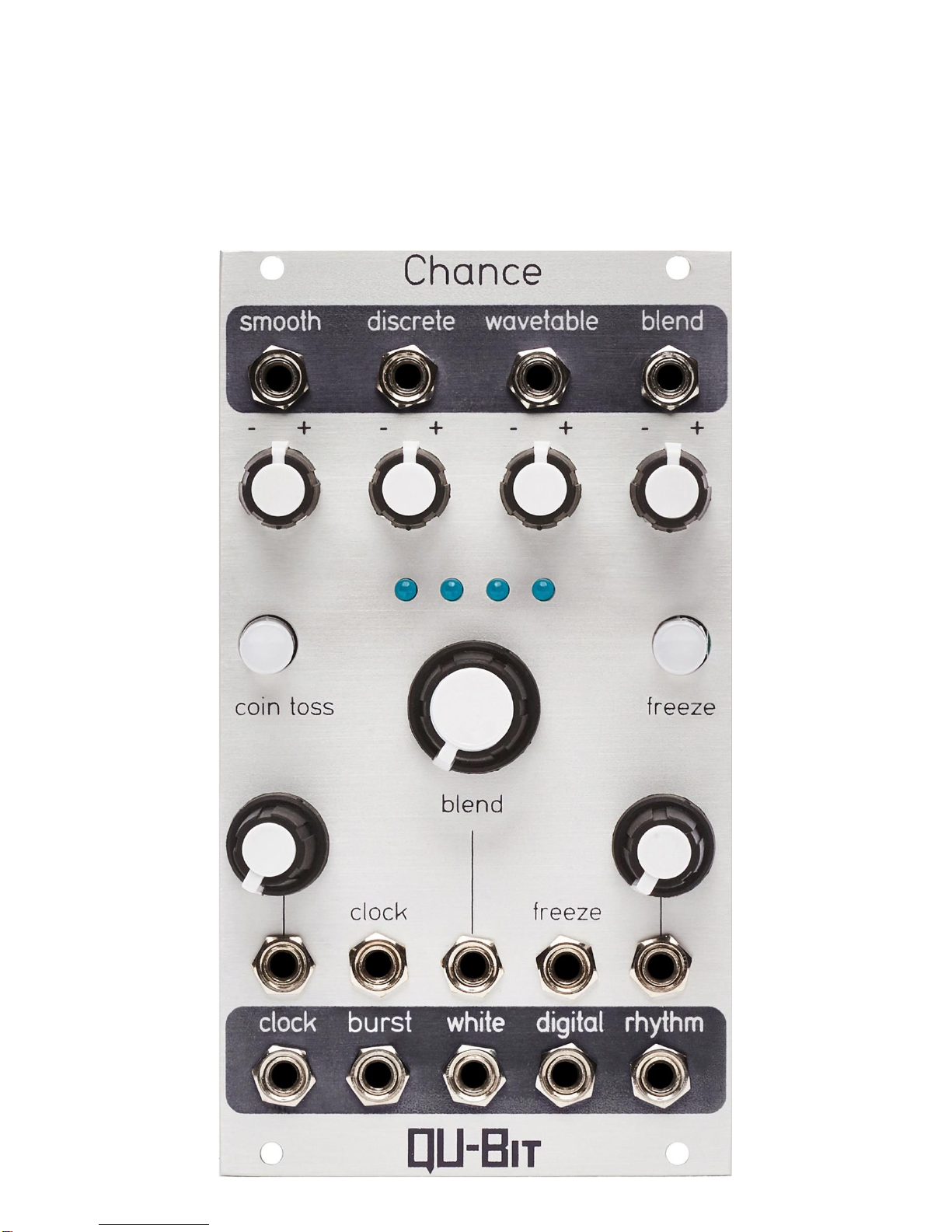
Chance is a unique modulation source that uses chance operations to create musical
voltages. Inspired by John Cage’s use of the Chinese divination text, I Ching, Chance
generates random voltages in response to a digitally generated coin toss.
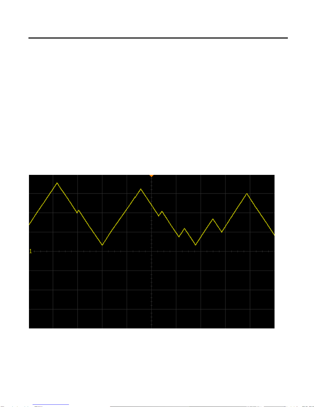
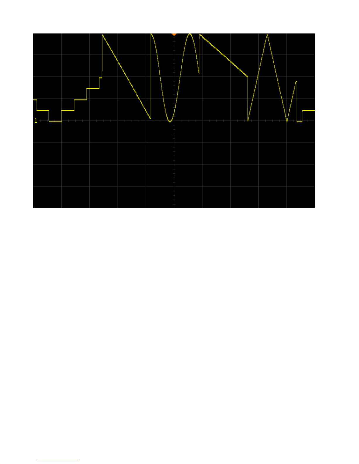
Four distinct algorithms provide signals like smooth and discrete, while the wavetable
and blend outputs take full advantage of its microcontroller core, utilizing lookup
tables, and digital interpolation to create a one-of-a-kind voltage source. Upon each
successive clock pulse, coin toss seeds all outputs with new randomly chosen values.
Freeze stops everything in its tracks and holds each output at its current state. After
countless hours, Chance will continue to surprise with new, unbelievable
improvisations.
-Chance operations in Eurorack
-Four random voltage outputs with attenuverters
-Unique voltage generation algorithms
-Erratic gate burst and autonomous rhythm trigger outputs
-Freeze control stops everything in its tracks
-Coin toss random voltage reseed
-Digital noise and analog white noise outputs
-Steady master clock output with rate CV
3
Table of Contents
Installation/Specifications 4
Chance 5
General Functions Overview 6
4
Installation
To install, locate 14 HP of space in your Eurorack case and confirm the positive 12
volts and negative 12 volts sides of the power distribution lines. Plug the connector
into the power distribution board of your case, keeping in mind that the red band
corresponds to negative 12 volts. In most systems, the negative 12 volt supply line is
at the bottom. The power cable should be connected to the Chance with the red band
facing the bottom of the module.
Specifications
Format: 14 HP Eurorack module
Depth: 34mm (Skiff Friendly)
Max Current: +12V = 45mA
-12V = 17mA
5
1
3
5
7
2
4
6
8
12
9
10
20
13
14
15
11
21
22
23
16
17
19
24
18
6
General Functions Overview
1. Smooth Output:
The Smooth Output emits a continuously changing random voltage based on a rate
and a destination.
The voltage moves toward the destination at a rate specified by the Rate Knob and the
Rate CV input.
Upon reaching the destination, receiving a new clock pulse, or if the Coin Toss Button
is pressed, a new random destination will be seeded and the voltage will begin to
move toward the new destination.
It is important to note that if Chance is externally clocked, the rate at which the voltage
moves to its next destination is set by the Rate knob and the Rate CV input.
Range: ±8V
7
2. Smooth Attenuverter:
Attenuation and inversion control of the Smooth Output.
If the knob is far left, voltage will have an output range of 0V to -8V.
If the knob is far right, voltage will have an output range of 0V to +8V.
3. Discrete Output:
The Discrete Output emits a new steady voltage when a clock pulse is received or if
the Coin Toss Button is pressed.
Range: ±8V
4. Discrete Attenuverter:
Attenuation and inversion control of the Discrete Output.
If the knob is far left, voltage will have an output range of 0V to -8V.
If the knob is far right, voltage will have an output range of 0V to +8V.
8
5. Wavetable Output:
The Wavetable Output emits a continuously changing tempo-synced LFO.
If a clock pulse is received or if the Coin Toss Button is pressed, a new random
wavetable and division or multiplication of the clock rate is selected.
If a division is selected, the algorithm waits for the number of clock pulses equaling the
factor of the division before selecting new values.
Wavetables are as follows:
•Cosine
•Triangle
•Saw
•Ramp
•Stepped Triangle
•Inverted Cosine
•Inverted Triangle
•Inverted Stepped Triangle
Rhythmic Division/Multiplication values are as follows:
•/4 (whole notes)
•/2 (1/2 notes)
•= (1/4 notes)
•*2 (1/8 notes)
•*4 (1/16 notes)
Range: ±8V
9
6. Wavetable Attenuverter:
Attenuation and inversion control of the Wavetable Output.
If the knob is far left, voltage will have an output range of 0V to -8V.
If the knob is far right, voltage will have an output range of 0V to +8V.
7. Blend Output:
The Blend Output allows for smooth morphing between the Smooth, Discrete, and
Wavetable algorithms.
The fourth algorithm is an automated distribution of the three other algorithms.
If a clock pulse is received or if the Coin Toss Button is pressed, all algorithms are
reseeded, and a new weighted average of all three algorithms is calculated.
It is important to note that the voltage present at the Blend Output will never be
identical to the voltage present at the Smooth, Discrete, or Wavetable Outputs,
regardless of the Blend Knob setting.
Range: ±8V
10
8. Blend Attenuverter:
Attenuation and inversion control of the Blend Output.
If the knob is far left, voltage will have an output range of 0V to -8V.
If the knob is far right, voltage will have an output range of 0V to +8V.
9. Blend Indicators:
LED indication of the of the currently selected algorithm emitting from the Blend Output.
The LEDs are arranged in the same order as the four algorithms
•If the first LED is illuminated, the Smooth algorithm will be selected
•If the first and second LEDs are illuminated, a blend of the Smooth and Discrete
algorithms will be selected
•If the second LED is illuminated, the Discrete algorithm will be selected
•If the second and third LEDs are illuminated, a blend of the Discrete and
Wavetable algorithms will be selected
•If the third LED is illuminated, the Wavetable algorithm will be selected
•If the third and fourth LEDs are illuminated, a blend of the Wavetable and Blend
algorithms will be selected
•If the fourth LED is illuminated, the Blend algorithm will be selected