Quadelectra Transient Splitter User manual


Operation Manual
1. Welcome To Transient Splitter
Thank you for your purchase on Quadelectra Transient Splitter Rack
Extension for Reason. Transient Splitter is the little brother to our
previously released Stereo Splitter, and just like the name su ests,
Transient Splitter is to transients what Stereo Splitter was to... stereo :)
We really hope you enjoy usin Transient Splitter.
1.1. What Are Transients
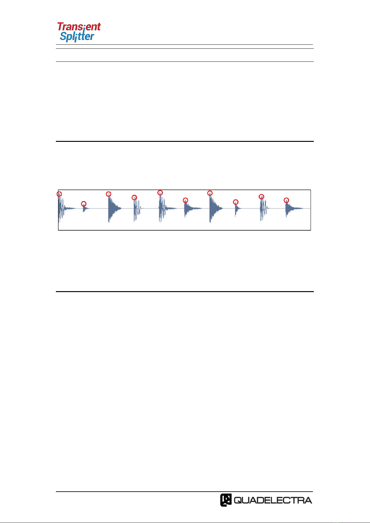
Transients are short bursts of sound found mostly in percussive sounds or
sounds with sharp attacks. The first few milliseconds of a snare hit, or of a
picked strin for example.
Fig.1.1: An audio signal with its transients circled
In mixin mana in the level of the transients of such sounds, can either
“push” an instrument, to the front or at the back the mix, or -if added at a
roup or in the master bus- it can add clarity to the entire track.
1.2. What Is the Transient Splitter by Quadelectra
Usually you tame your transients usin a Transient Shaper, that takes an
audio input, processes the transients, and outputs the result.
Transient Splitter, althou h it can be used as a Shaper, takes an input audio
si nal and splits it into two different parts. The actual transients of a si nal,
and the body part (the rest).
These two parts can be either mixed to ether in different levels, which
works almost like a transient shaper, or you can also hook up the auxiliary
outputs of the unit at the rear panel, and drive each portion -the transient
and the body parts- throu h a different effects chain.
This feature opens entirely new possibilities for processin . Have a lead
uitar e. . with mild saturation in the transient FX chain and a heavy
distortion in the body FX chain, in order to make sit better in your mix.
Reduce plosives from vocals without crushin dynamics, add bass to your
kicks without mufflin the low end of the mix, and many more.
The applications are limitless.
Pa e 3

Operation Manual
1.3. How Transient Splitter Works
Instead of usin a set of envelope followers, Transient Splitter uses an
envelope to extract the detected transients from the audio input si nal.
This method ensures more consistent results. The transients are subtracted
from the input si nal and the result of that operation produces the body
part.
Below is a dia ram that explains this operation
Fig.1.2: The process diagram of the Transient Splitter
Pa e 4
Audio Si nal
Event

Operation Manual
2. ront Panel
The front panel is divided into five distinct sections, each with its own
back round color. Goin from left to ri ht these are:
•Basic Controls (Black)
•Detection Controls (Grey)
•Envelope Controls (Oran e)
•Transient Controls (Red)
•Body Controls (Blue)
Fig.2.1: Transient Splitter Front Panel
Let’s take a closer look to the controls and the functionality of each section.
•Basic Controls (Black): These control the most fundamental
properties at the be innin and the end of the processed si nal.
◦On / Off / Bypass Switch: Like in any standard Reason Effect
Device, this switch turns the device on, off or puts it in bypass
mode.
◦Input Gain: This knob controls the ain of the input si nal that’s
bein fed to the envelope. Note that IT DOES NOT chan e the
output amplitude of the si nal.
Normally you’d use Input Gain to rectify the dynamic ran e that
the envelope follower has to work with, if the incomin audio
si nal is weak.
◦Output Volume: The output volume just before the si nal leaves
the device. The output volume affects only the main output of the
device. Auxiliary outputs are not affected.
•Detection Controls (Grey): Transient Splitter uses an envelope
follower set up to detect transients. This roup of controls, deals
with the detection aspects of the envelope follower and the input
si nal.
Controls of this roup are:
◦ink /R: When enabled a sin le envelope follower is used to
detect si nals in both Left and Ri ht channels.
If disabled two different envelopes will detect si nals from Left
Pa e 5

Operation Manual
and Ri ht channels separately, causin different tri ers for each
channel.
This switch does not produce any results when Transient Splitter
is used in mono.
◦Sens (Sensitivity): Use this knob to dial the desired sensitivity for
the tri er. Lower values make the envelope follower more
sensitive and catch more transients. Hi her values have the
opposite effect, reducin the sensitivity and therefore tri erin
less transients for processin .
Fig.2.2: Sensitivity determines the level a ove
which, any transients will trigger the effect
◦Recovery: Recovery knob sets the amount of time the device will
suspend any tri erin from the envelope, once a tri er is hit.
You can increase the delay, if for example you want the transients
on certain time intervals to be heard in a busy beat, discardin
any intermediate ones.
Fig.2.3: Although some transients exceed the sensitivity threshold,
they are ignored since they fall inside the recovery time span.
•Envelope Controls (Orange): Once a transient is detected, Transient
Splitter uses an AHD (Attack, Hold, Decay) envelope to extract it from
the rest of the si nal.
The Envelope Controls, affect the properties of this envelope. They
are common for both left and ri ht channels, re ardless of the L/R
Link switch.
Fig.2.4: The magenta line shows the amplitude applied y the
AHD envelope in order to extract the transients from a signal.
Pa e 6

Operation Manual
(As a result of the previous diagram)
These are the controls for the envelope:
◦Attack Curve: You can switch between three different settin s
that define the way the attack rate chan es. See below for an
explanation of these settin s.
◦Attack Time: The time in milliseconds of the envelope attack
sta e.
◦Hold Time: The time in milliseconds that the envelope will hold
the ate open, for the si nal to pass.
◦Decay Time: The time in milliseconds of the envelope decay
sta e.
◦Decay Curve: You can separately define what kind of curve the
Attack and Decay portions of the envelope will have.
Su sequent trigger hits will not retrigger the envelope unless it has
entered the decay stage.
Attack / Decay Curves
Each one of the Attack and Decay curves can be set to one of these
three settin s: (from top to bottom):
▪Lo arithmic
▪Linear
▪Exponential
◦Trigger amp: This lamp flashes every time a tri er is detected
by the Transient Splitter.
•Transient Controls (Red) / Body Controls (Blue): These two roups
contain the same set of controls. One is dedicated to the Transient
part and the other to the Body part of the processed si nal.
◦Mute Switch: This switch mutes the portion of the si nal from the
output. The switch does not affect the si nal sent to auxiliary
outputs.
◦Volume / evel: This knob sets the level of the si nal bein fed to
the output. The knob does not affect the si nal sent to auxiliary
outputs.
Pa e 7

Operation Manual
◦Aux Connection amp: This lamp is lit when the auxiliary outputs
are connected to another device.
Fig.2.5: The final product with respect to the previous figure.
The red area is the transient part of the input audio,
while the lue is the ody of the signal.
Pa e 8

Operation Manual
3. The Rear Panel
Figure 3.1: Transient Splitter Rear Panel
Transient Splitter’s rear panel, is divided in 5 sections. Startin from left to
ri ht, these are:
•Main Inputs ( /R): As expected, incomin si nal to be processed is
connected to this pair of inputs. You can either process a stereo
si nal, or a mono by connectin only the Left (L) channel.
•Main Outputs ( /R): Likewise, these work as expected, but for the
out oin processed si nal.
•Transient Aux Output ( /R): This pair of outputs forwards the
transient parts of the incomin si nal for separate processin .
•Body Aux Output ( /R): This pair of outputs forwards the body parts
of the incomin si nal for separate processin .
•CV Inputs Group: You can control a set of Transient Splitter’s
parameters usin external devices in real time. These are:
◦Tr (Transient evel): Controls the level of the transient part
that is fed to the mixer. The settin does not affect the output
volume from the si nal fed to the Transient auxiliary output.
◦Bo (Body evel): Controls the level of the body part that is fed
to the mixer. The settin does not affect the output volume from
the si nal fed to the Body auxiliary output.
◦Atk (Attack): Controls the attack time of the AHD envelope, that
modulates the transients’ amplitude.
◦Hld (Hold): Controls the time that the AHD envelope that
modulates the transients, stays open.
◦Dcy (Decay): Controls the decay of the AHD envelope that
modulates the transients’ amplitude.
◦Sens (Sensitivity): Controls the sensitivity of the tri er.
•CV Outputs:
Pa e 9

Operation Manual
◦Trig CV Out: Fires a CV Tri er once a transient has been
detected by the Rack Extension device.
◦Env CV Out: Similar to Tri er CV Out, but instead sends the
complete AHD envelope level
Pa e 10

Operation Manual
APPENDIX I: MIDI CC Map
Below you can see the Transient Splitter MIDI Continuous Controls Map.
CC # Description
12 Envelope Attack Time
13 Envelope Hold Time
14 Envelope Decay Time
15 Envelope Follower Sensitivity
16 Transient Volume
17 Body Volume
18 Input Gain
19 Output Volume
20 Link L/R
21 Transient Mute
22 Body Mute
23 Recovery Time
24 Envelope Attack Curve
25 Envelope Decay Curve
Pa e 11

Operation Manual
TABLE O CONTENTS
1. Welcome To Transient Splitter....................................................3
1.1. What Are Transients...........................................................3
1.2. What Is the Transient Splitter by Quadelectra............................3
1.3. How Transient Splitter Works................................................4
2. Front Panel...........................................................................5
3. The Rear Panel.......................................................................9
APPENDIX I: MIDI CC Map.............................................................11
TABLE OF CONTENTS..................................................................12
Pa e 12
Table of contents
Popular Media Converter manuals by other brands

Monoprice
Monoprice 8667 user manual

Hirschmann
Hirschmann OZDV 2471 P Description and operating instructions

TechSide
TechSide EASY CAPTURE manual

PAC
PAC L.O.C.PRO ADVANCED LPA-E4 quick start guide

DCS
DCS Scarlatti Upsampler user manual

pumpa
pumpa E-LINE DRIVE-02M Translation of the original instruction manual