Quality Fiber and RF EDFA-1901 User manual

1
15
55
50
0n
nm
m
E
Er
rb
bi
iu
um
m
D
Do
op
pe
ed
d
F
Fi
ib
be
er
r
A
Am
mp
pl
li
if
fi
ie
er
r
·
··
· EDFA-1901 U
US
SE
ER
R
M
MA
AN
NU
UA
AL
L
19dBm Tot l Output Power
Du l 120 VAC Power Supplies
SNMP St tus Monitoring

CONTENT
1.0
PRODUCT SUMMARY ........................................................................ 1
1.1
Product summ ry ............................................................................ 1
2.0
AMPLIFIER CONTROLS, INDICATORS, AND ALARMS ........................ 2
2.1
The oper tion of the front p nel ........................................................ 2
3.0
EQUIPMENT OPERATION PRINCIPLE ............................................... 5
3.1
EDFA-1901 Series mplifier circuit principles ....................................... 5
3.2
CNR degr d tion ch rt ..................................................................... 5
4.0
DESCRIPTION OF STATUS ALARM .................................................... 6
5.0
OPERATION NOTICE ........................................................................ 6
6.0
GUARANTEE AND REPAIR ITEMS ..................................................... 7

P ge 1 of 7
1.0
PRODUCT SUMMARY
1.1 Pro uct summary
The EDFA is the gre t chievement of opto-electronics in the intern tion l
inform tion field in recent dec de. Its ppe r nce h s le d to revolution
in optic l communic tions, bringing revolution ry progress for CATV
tr nsmission with high qu lity pictures over long dist nces, nd llowing
the CATV oper tor to cover l rge re s with high customer density, gre tly
reducing the building costs of the network.
This EDFA-1901 mplifier dopts the m ture 1550nm module technology
from st te-of-the- rt US m nuf cturer, ssuring both high qu lity nd
high reli bility for core electronics nd optics.

P ge 2 of 7
2.0
AMPLIFIER CONTROLS, INDICATORS, AND ALARMS
This section of the m nu l will give n overview of the v il ble menus in the
EDFA-1901 mplifier. All instructions in Section 2.0 refer to the represent tion of
the front p nel shown in the di gr m below. The user c n scroll through the menus
by using the push buttons th t re on the front p nel nd re loc ted in the right
of the LCD screen.
2.1 The operation of the front panel
2.1.1 Open menu
A. Plug in 120V AC power supply
B. Turn on power switch in the re r p nel, then input power nd turn
on the l ser key in the front p nel
Front p nel shows “KEY ON…”. L ser st tus l mp turns green from red,
nd the m chine enters self-checking. After checking, it enters working
st tus nd displ y “Description”.
2.1.2 Start-up main menu
Press
▲
\
▼
button nd the following menu will be displ yed in
sequence.
Menu # 1 - Description
Re d-only menu, tells the model of this equipment
Menu # 2 - S/N
Re d-only menu, tells the seri l-number
Menu # 3 - INPUT
Re d-only menu, tells the input optic l power
Menu # 4 - SET OUTPUT
Adjust ble list, set the output power in dBm.
Menu # 5 - OUTPUT
Re d-only menu, tells the output optic l power
Menu # 6 - PUMP BIAS1
Re d-only menu, tells the current of pump

P ge 3 of 7
Menu # 7 - PUMP BIAS2
Re d-only menu, tells the current of pump
Menu # 8 - TEC1
Re d-only menu, tells the current of pump in cooling/he ting
situ tion
Menu # 9 - TEC2
Re d-only menu, tells the current of pump in cooling/he ting
situ tion
Menu # 10 - PUMP TEMP1
Re d-only menu, tells the temper ture of pump
Menu # 11 - PUMP TEMP2
Re d-only menu, tells the temper ture of pump
Menu # 12 - +5V Rea s
Re d-only menu, displ ys the volt ge +5V
Menu # 13 - -5V Rea s
Re d-only menu, displ ys the volt ge -5V
Menu # 14 - UNIT TEMP
Re d-only menu, tells the temper ture of ch ssis
Menu # 15 - IP
Adjust ble list, displ ys the IP ddress of SNMP
Menu # 16 - Sub
Adjustable list, display the address of net mask
Menu # 17 - GW
Adjust ble list, displ ys the g tew y ddress of SNMP
Menu # 18 - TR1
Adjust ble list, displ ys the TRAP1 ddress of SNMP
Menu # 19 - TR2
Adjust ble list, displ ys the TRAP2 ddress of SNMP
Menu # 20 - Soft Version
Re d-only menu, tells the soft version
Menu # 21 - Har Version
Re d-only menu, tells the h rd version
Menu # 22 - Reset Settings
Adjust ble list, tells the reposition Setting

P ge 4 of 7
2.1.3 Menu assistant manual
1. Input power (INPUT):
If the Input power >+10 dBm, the displ y re ds HIGHER;
If the Input power <-7.5 dBm, the displ y re ds LOWER.
2. Output (OUTPUT):
When the input displ ys HIGHER or LOWER, the output power
displ ys NO OUTPUT.
3. L ser temper ture (TEMP): °C. The l ser temp is set in the r nge
of 20°C~30°C. If the detected temp exceeds the r nge, the red
light will show n l rm nd the power supply of the l ser will be
off utom tic lly.
4. Bi s (BIAS): Bi s is the key index of the l ser. If the fixed r nge is
exceeded, the power supply of the l ser will be off utom tic lly
to protect the l ser
5. +5V volt ge(+5V READS) >±0.5V l rm.
-5V volt ge(-5V READS) >±0.5V l rm.
6. Press
▲
\
▼
key to mend the IP ddress menu th t needs to be
mended. Press
▲▼
t the s me time to enter the menu, press
▼
to choose the mended pl ce, push
▲
to mend, nd then
press
▲▼
to enter into s ve nd exit.
For ex mple, mend IP setup menu, IP: 192.168.000.015; if you
w nt to ch nge 5 to 6, use
▲▼
to enter the IP menu, then press
▼
to choose the pl ce of 5, press
▲
key to ch nge 5 to 6, nd
then press
▲▼
to s ve mended IP:192.168.000.016

P ge 5 of 7
3.0
EQUIPMENT OPERATING PRINCIPLES
3.1 EDFA-1901 Series amplifier circuit iagram
3.2 CNR egra ation chart
5
4
3
2
1
0
1 2 3 4 5 6 7 8 9 10
Amplifier input power
(
dBm
)
CNR inferiority
(
dB
)

P ge 6 of 7
4.0
DESCRIPTION OF STATUS ALARM
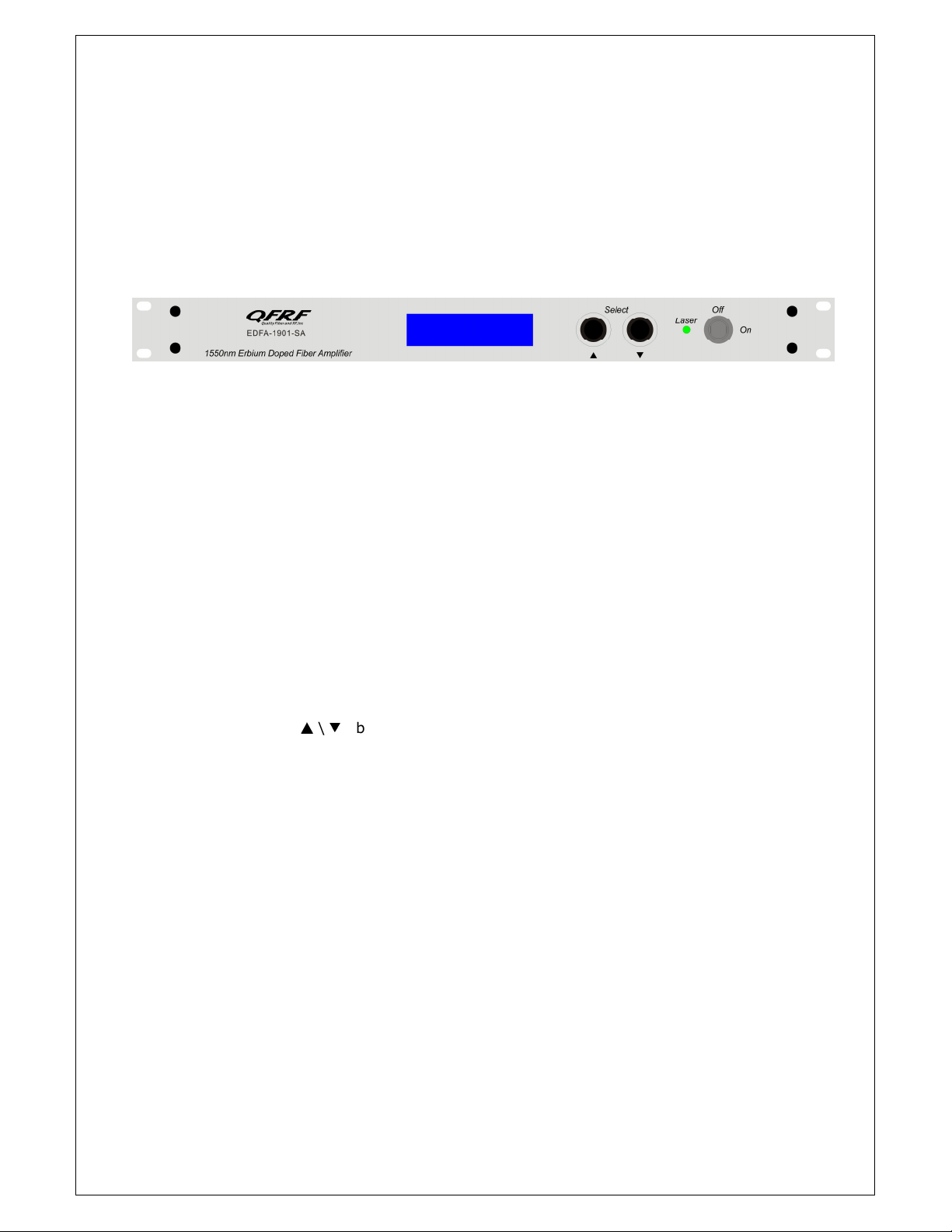
Working st tus indic tion (LED) is ne r the powers supply switch in the front p nel.
When it is green, the device is working properly; when it is red, the l ser does not
work; when it is red blinking, there is n l rm.
A. With 120V power supply, if the EDFA is functioning properly, the digit l p nel
will displ y “READY: KEY OFF” nd there is Red light.
B. Turn on with the key, the digit l p nel will displ y “KEY OFF”. After few
seconds, the l ser is turned on utom tic lly nd the indic tion light turns
into Green from Red.
C. Pressing the
▲
\
▼
keys will llow you to displ y the oper ting p r meters .
D. If ny f ult listed bove h s occurred, there will be n l rm (Red blinking
LED), the Microprocessor will shut down the l ser utom tic lly, nd digit l
p nel will show the re son of the f ult.
E. In order to protect the l ser, the power supply of the l ser h s time-del y
function. After turning on the keyswitch, the l ser will st rt to work fter 10
second del y.
5.0
OPERATION NOTICE
1. The m chine should h ve good grounding with grounding resist nce<4
Ω
.
2. The m chine dopts high perform nce, high reli bility, nd ste dy volt ge
switch power supply. It h s const nt volt ge overflow protection nd c n work
in 120 VAC electric network. The micro-processor c n monitor the output DC
volt ge. If the Fuse is melted broken, it will show th t the m chine’s inner
p rts h s occurred problems.
3. In order to m ke sure reflection loss is ≥45dB, we use SC/APC connector;
other type (such s FC/PC, SC/PC, or ST/PC) h ve insufficient reflectivity. Keep
the connector cle n when inst lling, nd fter sever l plug-in/outs, cle n it
with gre seless cotton cloth nd nhydrous lcohol.
4. Do not turn on the m chine without the fiber output connected or without
protective cover t the connector end. Otherwise the l ser could do h rm to
the hum n body, especi lly the eyes.

P ge 7 of 7
6.0
WARRANTY AND REPAIR ITEMS
1. E ch EDFA unit comes with full one-ye r p rts nd l bor gu r ntee.
Ple se cont ct QFRF t (772)545-9757 if you h ve ny problems.
2. The micro-processor softw re of the device h s the function of monitoring
l ser st tus, digit l displ y, trouble l rm, network m n gement etc. The
pump l ser will not be d m ged only by m n-induced f ctor. If the Red LED
is blinking (Al rm), ple se cont ct QFRF for rep irs or troubleshooting the
problem. The user should not open the top cover for rep irs without the
permission of QFRF, otherwise the w rr nty m y be inv lid.
3. Lifelong m int in nd upgr de c n be provided even though the gu r ntee
period is expired.
4. If component is d m ged by m n-induced f ctor, m teri l fee will be
ch rged.
QUALITY FIBER AND RF, INC
8941 SE DUNCAN ST
HOBE SOUND, FL 33455
(772)545-9757
http://www.qfrf.com
jeff@qfrf.com
Table of contents
Popular Amplifier manuals by other brands

Com-Power
Com-Power ACS-230-25W instruction manual

Nissindo
Nissindo MA-1330 POWER operating instructions

WiMo
WiMo RANGER 811H operating manual

Magnat Audio
Magnat Audio MA 700 Important notes for installation & warranty card

ALLNIC AUDIO
ALLNIC AUDIO T-1800 MK2 owner's manual

Marantz
Marantz MR2020 user guide