manuals.online logo
Brands
  1. Home
  2. •
  3. Brands
  4. •
  5. Quanser
  6. •
  7. Network Hardware
  8. •
  9. Quanser NI M Series User manual

Quanser NI M Series User manual

Quick Start Guide: NI M and X Series Terminal Board
1. NI M and X Series Terminal Board
2. NI PCI/PCI Express Data
Acquisition Device
3. 68-pin shielded ribbon cable
(NI SHC68-68, can be purchased
with NI PCI/PCIe DAQ device)
4. RCA to RCA (analog loopback) cable
(supplied with NI M and X Series)
5. Quanser Workstation Resources*
(includes User Manual and
Quick Start Guide)
Make sure your Data Acquisition (DAQ) Device includes the following components:
5
CAPTIVATE. MOTIVATE. GRADUATE.
Solutions for teaching and research. Made in Canada.
USER MANUAL
NI M and X Series Terminal Board
Set Up and Configuration
Quanser educational solutions
are powered by:
3
Check Components and DetailsSTEP 1
Install NI LabVIEW™ Add-onsSTEP 3
4
Additional Components Required
To complete the NI Terminal Board set up, you will need the following:
STEP 2
Quanser Rapid Control Prototyping Toolkit for NI LabVIEW™
Visit www.ni.com/labviewtools/rcp
Note: must be purchased separately.
2
• LabVIEW™
• NI-DAQmx
• Quanser Rapid Control Prototyping Toolkit®
Make sure LabVIEW™ and required add-ons are installed.
Note: The Quanser Rapid Control Prototyping (RCP) Toolkit must be
installed after LabVIEW. See the RCP Toolkit Installation Guide for
more information www.quanser.com/products/rcptk/documentation
*Download from the RCP Toolkit Resources
at www.ni.com/labviewtools/rcp.
1
ni.com/labviewtools/rcp
RCP Toolkit
For this step you will need the following:
NI PI PCI/PCI Express DAQ device
PCI/PCI Express System Slot
Insert the NI DAQ device into the applicable PCI/PCI Express
system slot. Gently rock, do not force, the device into the place.
You cannot install PCI Express devices in PCI slots and vice versa.
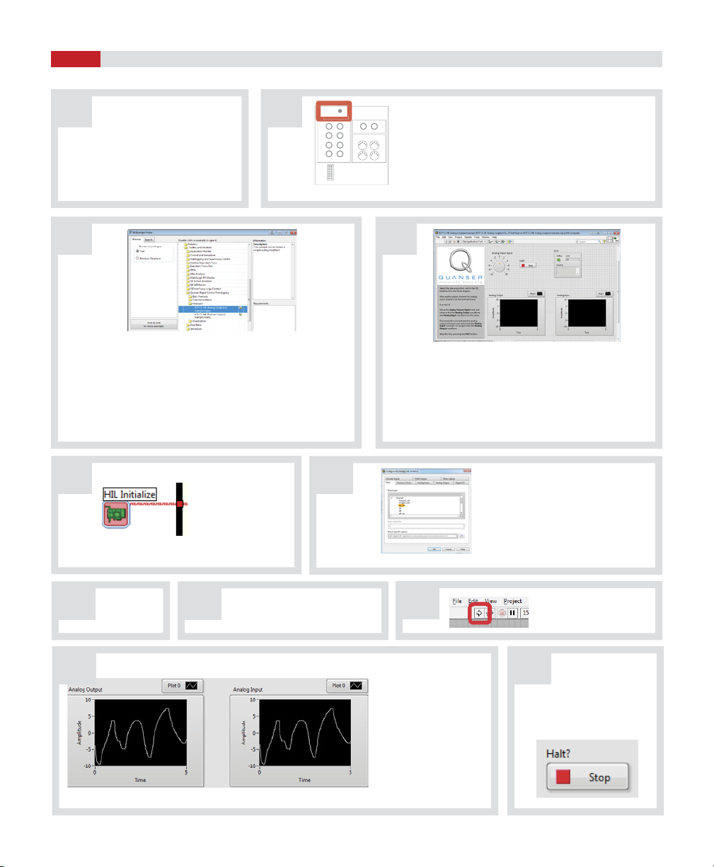
DIO 0:7
Analog Input Analog Output
Encoders
Power
6
5
4
7
2
1
0
310
31
20
Install Data Acquisition Device
Configure NI DAQ Device
STEP 4
STEP 5
The installation procedure for the NI PCI/PCIe data acquisition device is shown below. For detailed instructions, go to
http: //www.ni.com/gettingstarted/ or the User Manual (enclosed with shipment)
Windows is a registered trademark of Microsoft Corporation in the United States and other countries.
Conrm that the software components listed
in Step 3 have been installed. Power o and unplug your computer.
Remove the computer cover and/or the
expansion slot cover.
Touch a metal part of the computer to discharge
any static electricity.
AB
C D
Secure the device mounting
bracket to the computer back
panel rail.
F
E
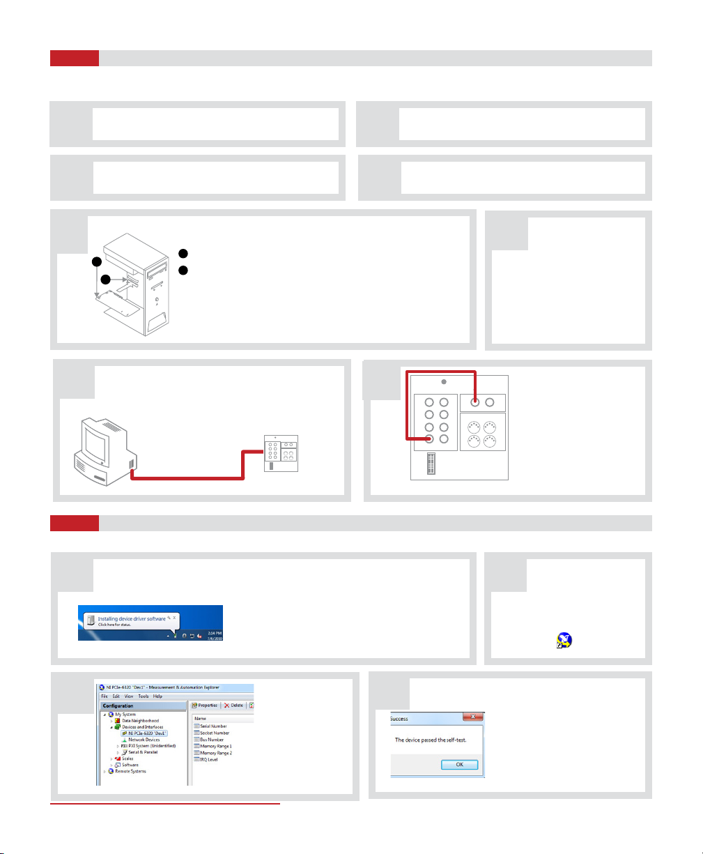
Using the 68-pin NI shielded ribbon cable, connect the
CONNECTOR 0 socket on the back of the installed
NI DAQ device to the Connector JO socket on the NI
M and X series Terminal Board.
GHUsing the RCA to RCA cable,
connect the Analog Output
Channel #0 on the NI M
and X Series Terminal Board
to Analog Input Channel
#0 on the NI M and X Series
Terminal Board.
Expand Devices
and Interfaces
to conrm your
device is detected.
Right-click the device and select
Self-Test. If you receive an error,
refer to the NI KnowledgeBase
(http://www.ni.com/kb/) with
your specic error code.
With your DAQ hardware now installed, power on
your PC. Windows1 should automatically detect
the presence of the new NI DAQ device and install
device software automatically.
Note: If you do not have a current version of
LabVIEW™ installed, the driver installation will fail.
Run the Measurement and
Automation Explorer (MAX).
CD
A B
Complete the following steps to congure your software for use with NI PCI/PCIe DAQ device.
1
2
68-pin shielded ribbon cable
NI M and X Series
Terminal Board NI M and X Series Terminal Board
DIO 0:7
Analog Input AnalogOutput
Encoders
Power
6
5
4
7
2
1
0
310
31
20
1
2
Running the DAQ Test
STEP 6
Make sure your PC is
powered ON and that you
connected the RCA to RCA
cable as shown in Step 3H.
Go to the block
diagram (CTRL-E)
and double click on
the HIL Initialize
Express VI
In the RCP CL HIL Analog Loopback Example.lvproj
example, double-click on the RCP CL HIL Analog
Loopback Example.vi le listed under My Computer.
Under the Main tab, select the data
acquisition device that is installed
on your system in the Board type
section (e.g., Q2-USB).
A
C
E
B
D
F
J K
Follow the procedure below to test your NI PCI/PCIe DAQ device.
Click on the STOP
button to stop
running the VI.
When manually moving
the Analog Output
Signal Knob of the VI,
both Analog Input and
Analog Output scopes
should display the same
trace. If not, go to the
Troubleshooting section.
I
HG Click on the
OK button.
Go to the Front Panel (CTRL-E)
of the VI (pictured in Step 4D).
Click on the white arrow
button to run the VI.
Verify that the LED on the Terminal Board is lit.
Otherwise, consult the troubleshooting guide.
DIO 0:7
Analog Input Analog Output
Encoders
Power
6
5
4
7
2
1
0
310
31
20
Analog Input
LabVIEW™ VI Front Panel
Configure HIL Initialize window
Scope view of the VI Front Panel
NI M and X Series Terminal Board
1. In LabVIEW, open the NI Example Finder by selecting Find
Examples... from the Help Menu
2. In the NI Example Finder dialog, when browsing
according to Task, open the Toolkits and Modules/Quanser
Rapid Control Prototyping/Hardware folder.
3. Double-click on the RCP CL HIL Analog Loopback Example.
lvproj LabVIEW project to open the RCP example.
Complete the following steps to congure your software for use with NI PCI/PCIe DAQ device.
LEARN MORE To find out about the full range of Quanser control experiments,
visit www.quanser.com
Review the following recommendations before contacting Quanser’s technical support engineers.
TROUBLESHOOTING
©2014 Quanser Inc. All rights reserved. LabVIEW™ is a trademark of National Instruments.
Full range of data acquisition devices from Quanser.
For further assistance from a Quanser engineer, contact us at
tech@quanser.com or call +1-905-940-3575.
Q8-USBQ2-USB QPIDe
V.2.2
STILL NEED HELP?
Q8-USB
You are getting
‘VI Missing’
messages when
opening the NI
DAQ Test.
•Make sure you installed the LabVIEW™ add-ons listed in Step 3, such as the Quanser
Rapid Control Prototyping Toolkit®.
When performing
the NI DAQ Test,
the Analog Input
scope does not
read anything.
•Make sure you made the RCA to RCA cable (analog loopback) connection on the
NI M and X series Terminal Board, as described in Step 4H.
• Verify that you selected the correct NI DAQ device in HIL Initialize block in the
NI DAQ Test VI.
•Load the Measurement and Automation Explorer (MAX) and conrm that the NI DAQ
device name is under Devices and Interfaces. If not, make sure the software listed in
Step 3 has been installed.
•Check that the Power LED is lit bright green on the DAQ terminal device.
If not, go to the next section.
The Power LED
on NI M and X
Series Terminal
Board is not lit.
• Verify that the 68-pin shielded ribbon cable is rmly connected from the NI DAQ
device to the connector on the NI M and X Series Terminal Board.
Q1-cRIO

This manual suits for next models

1

Popular Network Hardware manuals by other brands

D-Link DNR-326 Quick installation guide

D-Link

D-Link DNR-326 Quick installation guide

Funkwerk elmeg hybrid 300 installation guide

Funkwerk

Funkwerk elmeg hybrid 300 installation guide

ADC PG-Flex FLC-706 1A Technical practice

ADC

ADC PG-Flex FLC-706 1A Technical practice

NSFOCUS ADS installation guide

NSFOCUS

NSFOCUS ADS installation guide

evertz 7700 Series manual

evertz

evertz 7700 Series manual

Cabletron Systems WPIM-RT1 user guide

Cabletron Systems

Cabletron Systems WPIM-RT1 user guide

Alliance Laundry Systems NK100 installation instructions

Alliance Laundry Systems

Alliance Laundry Systems NK100 installation instructions

H3C WA6300-CMW710-R2444P01 Release notes

H3C

H3C WA6300-CMW710-R2444P01 Release notes

Iridium GO! exec user manual

Iridium

Iridium GO! exec user manual

McAfee MVM2200 Appliance Guide

McAfee

McAfee MVM2200 Appliance Guide

Toshiba TOSLINE-S20 instruction manual

Toshiba

Toshiba TOSLINE-S20 instruction manual

evertz TR-4800E user manual

evertz

evertz TR-4800E user manual

GRASS VALLEY K2 Summit 3G Service manual

GRASS VALLEY

GRASS VALLEY K2 Summit 3G Service manual

H3C SecPath M9000 NSQ1SUPB0 MPU manual

H3C

H3C SecPath M9000 NSQ1SUPB0 MPU manual

RTP 3000/06 Technical manual

RTP

RTP 3000/06 Technical manual

Huawei RT-FIC-1T1-V2 Specifications

Huawei

Huawei RT-FIC-1T1-V2 Specifications

Siemens RUGGEDCOM WIN5237 installation guide

Siemens

Siemens RUGGEDCOM WIN5237 installation guide

Beck com.tom M-BUS 6.1S Startup guide

Beck

Beck com.tom M-BUS 6.1S Startup guide

manuals.online logo
manuals.online logoBrands
  • About & Mission
  • Contact us
  • Privacy Policy
  • Terms and Conditions

Copyright 2025 Manuals.Online. All Rights Reserved.