Quantel Medical Optimus II User manual

XL OPT2 MT AN MAY 2005
SERVICE MANUALSERVICE MANUAL
SERVICE MANUAL
OPHTHALMIC LASER
16 16
25
10
I I I I I I I I I I I I I I I
70 60 50 40 30 20 10 0
III
5
III
+
II
+
1064NM LASER
QUANTEL MEDICAL SA
21,rueNewton,Z.I.duBREZET
63039 Clermont-Ferrand Cedex 2 - FRANCE
Tel : +33 (0) 473 745 745 - Fax : +33 (0) 473 745 700


SERVICE MANUAL
Rev.05/2005 P - 3
WARRANTY :-Anyadjusting andcalibratingprocedure describedinthis manual shall
beperformedonlybyTechnicians previously trainedby QuantelMedical.
-Anyfaultypartwillbereplacedbyastrictlyidenticaloneprovidedby
QuantelMedical.
-Forsafetyreasons,QuantelMedicalconsidersanyLasermoduleand
electronic PC Board as whole partial assembly :
*Defective PC Boardswillbereturned to QuantelMedicalfor
replacement
* Warranty will not be applied if a PC Board has been damaged during an
interventionorattempttorepair.
Warranty will not be applied unless these recommendations are
strictlyrespected.
CAUTIONS : Alltechnicianswillcarefullyrespectallthesafetyinstructionsherein
describedin this Servicemanual.
WARNING : Specialtrainingby Quantel Medicalfortechnicians is necessary to
ensureoptimumadjustmentandmaximumreliabilityofthewhole
instrument.
WARNINGS

SERVICE MANUAL
Rev.05/2005
P - 4
LASER SAFETIES :
Allstaffusingthislasersystem,orinchargeofitsmaintenance,mustbe
awareofthe following basic precautionstobetaken :
1- Neverlookstraight into thebeamorintoanyreflectingobjectable to
reflect the beam.
2- Limitthelaser room accesstotherequestedpersonnelonly,whois
alreadyaware ofthe precautionsto be taken.
3- Thelaserroommustbeindicatedwiththespeciallydesignedlabels.
4- Neverdirectthelaserbeam towardsanaperture.
5- Neverexposeanyreflectiveobjectorshinysurfacetothedirectbeam
path.
6-Switchofftheinstrumentcorrectlyaftereachuse.
WARNING : Laser power up to 30mJ at 1064 nm and laser Aiming beam 637 nm up to
1mW,maybe accessible uponremovalof console cover.
DONOTremovethecoverunlessinstructedtodosobyafactory-trained
technician.
Anyoneintheroomduringserviceormaintenancemustwearprotective
safety goggles.
PleasecheckcarefullytheseProtectiveGlassesareadequateforthe
laserwavelengthpresentintheOPTIMISII:
- Protection at 1064 nm : Reference N° 91 - B980 - 1100 OD6 - L5.
CAUTION : Use of controls or adjustments or performances other than those
specified herein may result in hazardous radiation exposure.
WARNINGS

SERVICE MANUAL
Rev.05/2005 P - 5
Page
WARNINGS AND CAUTIONS P - 3
TABLE OF CONTENTS P - 5
1- BLOCK AND WIRING DIAGRAMS P - 7
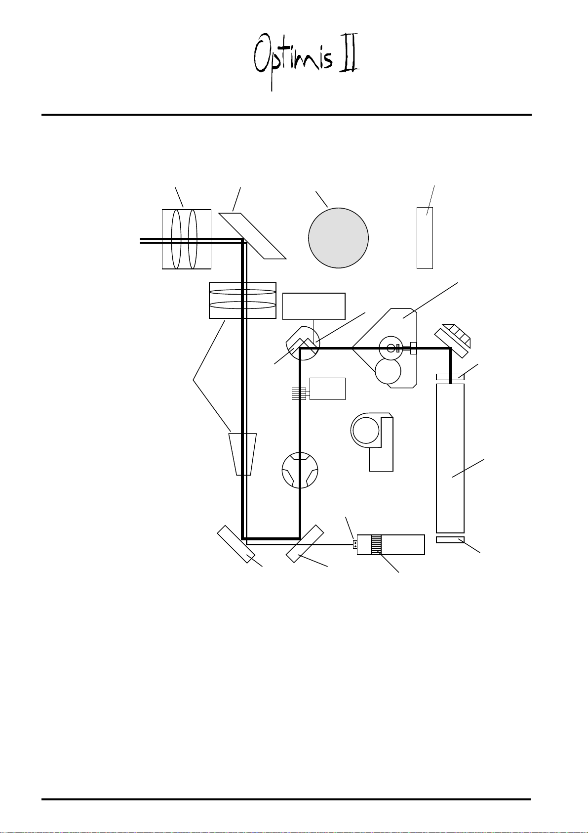
1-1 Optical block diagram P - 8
1-2Overallblock diagram P - 9
1-3 Description of the system P - 10
1-3-1Mainunit P - 10
1-3-2Laser head P - 13
2- DISASSEMBLING AND INNER VIEWS P - 15
2-1Overallview P - 16
2-2Laserconsoledisassembling P - 17
2-3Innerviewsof laser console P - 18
2-3-1Auxiliaryboard P - 19
2-3-2CPU board P - 19
2-3-3Interface board P - 20
2-3-4Displayboardand LCD P - 20
2-3-5Highvoltage power supply(analogmodules) P - 21
2-3-6Highvoltage capacitorboard P - 21
2-4 Slit lamp disassembling P - 22
2-5Innerviews of laser head P - 23
2-6Spareparts P - 24
3- LOCATION AND CONNECTOR PINS DESCRIPTION P - 25
3-1CPUboard P - 26
3-2Interface board P - 27
3-3Auxiliaryboard P - 30
3-4HVcapacitorboard P - 31
3-5HVpowersupplyboard P - 32
TABLE OF CONTENTS
4 - INSTALLATION P - 33
5 - SERVICE MODE P - 37
5-1 Accessing service mode P - 38
5-2Screeninservicemode P - 38
5-3 Defects and solutions list P - 39
5-4Quit the service mode P - 40
6 - SAFETY EXPLANATION P - 41
6-1Triggersafety P - 42
6-2Energy safety P - 43
6-3Shuttersafety P - 44
6-4 Joystick safety P - 44
6-5Knob position safety P - 44
6-6 Slit lamp safety P - 44
6-7Roomdoorswitch safety P - 44

SERVICE MANUAL
Rev.05/2005
P - 6
Page
7- ELECTRONIC ADJUSTMENTS P - 45
7-1Energy safety P - 46
7-2Energymetercalibration P - 46
7-3Highvoltage calibration P - 47
7-4 Display contrast adjustment P - 49
8- OPTICAL ADJUSTMENTS P - 51
8-1Checkingafterinstallation P - 52
8-1-1 Slit checking P - 52
8-1-2Aiming beam checking P - 52
8-1-3YAGand aiming beam checking P - 52
8-1-4Focuschecking P - 52
8-1-5Lasermodechecking P - 53
8-1-6Energychecking P - 53
8-2 Aiming beam adjustments P - 54
8-2-1 Aiming beam (and cross if available) centring in the slit P - 54
8-2-2Aimingbeamfocalizedandsharp P - 55
8-2-3 Aiming beam centring in the binocular cross P - 56
8-2-4Aiming beam not superposed on theYAG beam P - 57
8-2-5Pinhole adjustment P - 58
8-2-6 Focus adjustment of the aiming beam P - 59
8-3YAGadjustment P - 60
9- ROOM DOORSWITCH P - 63
9-1Roomdoorswitch P - 64
9-2 Room doorswitch with 532YAG adaptor P - 64
10- FUSES REPLACEMENT P - 66
VALIDATION - VAL -
TABLE OF CONTENTS

CHAPTER 1CHAPTER 1
CHAPTER 1CHAPTER 1
CHAPTER 1
BLBL
BLBL
BLOCK AND WIRING DIAOCK AND WIRING DIA
OCK AND WIRING DIAOCK AND WIRING DIA
OCK AND WIRING DIAGRGR
GRGR
GRAMSAMS
AMSAMS
AMS

SERVICE MANUAL
Rev.05/2005
P - 8
1-1 OPTICAL BLOCK DIAGRAM
Front mirror
Back mirror
YAG Laser and
flash lamp
Mirror M1
ENERGYMETER Mirror M2
Mirror M3
HUTTER
DEFOCU ELECTOR
AIMING BEAM
Mirror M4
Mirror M5
16
25
10
16
OBJECTIVE BINOCULAR MAGNIFICATION
ELECTION
DICHROIC MIRROR
BEAM
EXPANDER
TRIGGER
DEFOCU KNOB
PIN HOLE ROTATE
Energy elector
1064nm DOCTOR' FILTER
1 - BLOCK AND WIRING DIAGRAMS

SERVICE MANUAL
Rev.05/2005 P - 9
1-2 OVERALL BLOCK DIAGRAM
1 - BLOCK AND WIRING DIAGRAMS
INTERLOCK
SLIT LAMP
DETECTION SHUTTER
CONTROL AIMING BEAM
CONTROL ENERGYMETER
CONT ROL
Flash Lamp
Trigger
Lamp Bulb and
Pulse button
(Joysti ck)
ROOM
DOORSWITCH
OPTION
SLIT LAMP
LASER HEAD
Optional Energy
Display
Power Entry
Module
(Main Input
+ Fuses
+ Switch)
Connector
to see energy
in the ocular
Room
doorswitch
Connector
Slit Lamp
Male Connector High Voltage
Connector Sub-D 25
Male Connector
Room
doorswitch
Connector
Slit Lamp
Female
Connector High Voltage
Connector
Sub-D 25
Female
Connector
100V
to
240Vac
MAIN
UNIT
Rear Panel
High Voltage
POWER SUPPLY
24V / 1000V
HV CAP BOARD
INTERFACE BOARD
High Voltage
Feedback
Power
PowerData
CPU BOARD
PowerData
KeyboardLCD data
DISPLAY
&
KEYBOARD
UNIT
KeyboardLCD data
Front panel
AC / DC
CONVERTER
24V
Power Supply
Power Slit Lamp
Interlock
Emergency
Switch L.E.D. KEYSWITCH SLIT LAMP
ON SWITCH
LAMP
AUXILIARY BOARD
AC / DC
CONVERTER
12V
Power Supply

SERVICE MANUAL
Rev.05/2005
P - 10
1-3 DESCRIPTION OF THE SYSTEM
System is composed of two main sub assemblies:
- MAIN UNIT : Laser Console,
- LASER HEAD : Slit Lamp.
MAIN UNIT is a metal enclosure containing all of electronics sub units.
On the top of it, there is SLIT LAMP which holds LASER HEAD. MAIN
UNIT and LASER HEAD are connected to each other with two cables :
SIGNAL CABLE (CABLE1) and HIGH VOLTAGE CABLE.
1-3-1MAIN UNIT
MAIN UNIT is a metal enclosure containing all of electronics sub units:
- MAIN POWER SUPPLY / SWITCH / FUSE UNIT,
- MAIN DC POWER SUPPLY,
- AUXILIARY BOARD,
- INTERFACE BOARD,
- CPU BOARD,
- HIGH VOLTAGE CAPACITOR BOARD,
- HIGH VOLTAGE POWER SUPPLY BOARD,
- DISPLAY / KEYBOARD UNIT,
- BACK PANEL CONNECTORS.
1-3-1-1 MAIN POWER SUPPLY / SWITCH / FUSE UNIT
There are two separate fuses : one for Line and other for Neutral :
Fuses are 4AT/250V.
1-3-1-2 MAIN POWER SUPPLY (12V or 24V)
Input is : 85 to 264 VAC, 47 to 63 Hz with maximum input current of
1,2A.
Output is 12VDC or 24VDC and it can with covered enclosure deliver
up to 40W.
1 - BLOCK AND WIRING DIAGRAMS

SERVICE MANUAL
Rev.05/2005 P - 11
1-3-1-3 AUXILIARY BOARD
AUXILIARY BOARD distributes the electrical power to all sub-units and
control the front panel.
It is connected to MAIN POWER SUPPLY.
System can be switched ON again only, if the push button is rotated to
ON position. There are two options to turn ON the SLIT LAMP :
- first if user only wants to use SLIT LAMP without turning on the laser:
SLIT LAMP can be turned ON by pressing illuminated green SLIT LAMP
SWITCH. When the green light is ON, the slit lamp is lighted.
- second if user wants to use SLIT LAMP together with the laser : he
turns ON KEY SWITCH also the SLIT LAMP is lighted.
SLIT LAMP is connected to auxiliary board on the back panel LASER
CONSOLE.
The joystick pulse button and the lamp are controlled by this board.
1-3-1-4 INTERFACE BOARD
The INTERFACE Board (optocoupler interface) converts and distributes
electric power to other boards and laser head.
Its main functions are :
- power regulation : 5V voltage regulator (display),
12V voltage regulator (aiming beam).
- galvanic isolation : DC/DC power converter.
- digital and analog optocouplers isolation : computer signals.
- hardware control : - footswitch,
- high voltage,
- energy meter,
- shutter position,
- computer watch-dog.
- drivers for ENERGY OPTIONAL DISPLAY.
- speaker control.
- number of laser pulses selection and controlling of high voltage
power supply are on this board.
1 - BLOCK AND WIRING DIAGRAMS

SERVICE MANUAL
Rev.05/2005
P - 12
1-3-1-5 CPU BOARD
CPU BOARD is connected to INTERFACE BOARD via two connectors :
- one connector feeds all the digital and analog signals
- the other connector is for Computer power supply.
The CPU Board is the heart of the system :
- control of the display and front panel functions,
- control the High Voltage Capacitor Board via the interface board,
- control the laser head via the interface board.
1-3-1-6 HIGH VOLTAGE CAPACITOR BOARD
HIGH VOLTAGE CAPACITOR BOARD is connected to INTERFACE
BOARD.
The flash lamp of the laser head is supplied and controlled by this
board.
The high voltage is checked by the CPU Board (safety detection).
1-3-1-7 DISPLAY / KEYBOARD
DISPLAY / KEYBOARD unit is connected directly to Computer board.
Power for the back-light LED is fed from Interface board (5V).
Computer also controls via Interface two front panel LED diodes (green
for Stand-by and yellow for Ready) which are above STAND-BY /
READY button.
There are three keys on the front panel :
- PULSE SELECT BUTTON,
- COUNTER RESET BUTTON,
- STAND-BY / READY BUTTON.
1-3-1-8 BACK PANEL CONNECTORS
BACK PANEL CONNECTORS are :
- Main input,
- Interlock,
- Slit lamp,
- Option,
- Energy display,
- High voltage connector for laser head,
- Signal connector for laser head,
- GND terminal.
1 - BLOCK AND WIRING DIAGRAMS

SERVICE MANUAL
Rev.05/2005 P - 13
1-3-2LASER HEAD
LASER HEAD is located on the Slit lamp.
It is connected to MAIN UNIT via two cables :
- high voltage cable and signal cable (Cable1),
- signal cable has on Main unit side 25 pins SUB-D connector.
LASER HEAD sub-units are :
- TRIGGER,
- SHUTTER,
- ENERGYMETER,
- AIMING BEAM,
- SLIT / INTERLOCK,
- ENERGY DISPLAY (Option).
1-3-2-1 TRIGGER
The flash lamp of the laser head is power supplied via this trigger
board which is controlled by the CPU board.
1-3-2-2 SHUTTER
Purpose of a safety Shutter is to block the Laser pulse when it is not
wanted. Shutter is controlled by the CPU board via the Interface board.
There are two position detections : - when the shutter is closed,
- when the shutter is opened.
1-3-2-3 ENERGYMETER
ENERGY METER is measuring the energy of each laser pulse.
The calibration is done at two power levels : - 3mJ with P1.
- 10mJ with P2.
1-3-2-4 AIMING BEAM
Power is provided by a 1mW laser diode with the wavelenght of 637nm.
The intensity of a light is set by the knurled potentiometer on the right
side of the laser head.
1-3-2-5 SLIT / INTERLOCK
The slit lamp generator position is detected by a magnetic sensor just
below.
1-3-2-6 ENERGY DISPLAY
The option Energy display takes place between the oculars and the slit
lamp.
1 - BLOCK AND WIRING DIAGRAMS


CHAPTER 2CHAPTER 2
CHAPTER 2CHAPTER 2
CHAPTER 2
DISASSEMBLINGDISASSEMBLING
DISASSEMBLING
AND INNER VIEWSAND INNER VIEWS
AND INNER VIEWS

SERVICE MANUAL
Rev.05/2005
P - 16
I
0
Us e only wi th a 250 V fuse
Empl oyer uniquement av ec
un fusi ble de 250 V ++
QUANTEL MEDICAL
21, rueN ewton, Z.I. du Brézet,
63039 Cler m ont-Fer rand cédex 2
FRANCE
Tel : +33 (0) 473 745 745 - Fax : + 33 (0) 473 745 7 00
REF:
SN :
OPTIMIS II THISPRODUCT
COMPLIE SWITH 21 CFR 10 40
CAUTION :
U.S.FEDERALLAW
RESTRICTS THIS
OR ON ORDER
OF A PH YSICIAN
!IP 20
4AT
250V
50/60 Hz
150VA,1 Φ
100 - 230V~
AP
G
MADE I N FRANCE
0459 LASER CLASS4/IV
Nd:YAG Las er :1064nm,
30mJ Max,(3 pulses x 4ns)
VISIBLE AND/OR INVISIBLE LASER RADIATION
AVOID E YE OR SK IN EXPOS URE TO
DIRECTORSCATTE RED RADIATION
LASER CLASS2/II
Diode Laser:637nm,<1mW Max
CLASS IV L ASER PRODUCT
-1
-0
-1
-0
2 2
VIS EE
FOC U S
STOP
30
50
70
30
50
70
ENERGYENE RGY
FOCUS
I I I I I I I I I I I I I I I I I I I I I
0 50 60 70 80 90 80 70 60 50 4
1
2-1 OVERALL VIEW
3
2
4
5
6
Slitgenerator
2 - DISASSEMBLING AND INNER VIEWS

SERVICE MANUAL
Rev.05/2005 P - 17
-Toopen the laser console, it isnecessarytoremovedalltheplugsatthe
rearoftheOPTIMISII(thepowersupplyplug,theslitlampplug,HighVoltage
plugandtheslitlampcontrolplug).
-Removethe locking screw like indicatedonthebelowfigure.
-Slide the LaserConsole(pull it totowardsthe back)toaccess the inner.
2-2 LASER CONSOLE DISASSEMBLING
Remove this screw
WARRANTY VOID IF THE LASER CONSOLE AND
LASER HEAD OPENED : WITHOUT ADMISSION OF
THE QUANTEL MEDICAL TECHNICAL
DEPARTMENT
2 - DISASSEMBLING AND INNER VIEWS
I
0
Useonly wi th a 250V fuse
E mployer uniquement av ec
un fusi ble de 250 V ++
Slit
Lamp
Joystick
Footswitch Interlock H.V.
Voltage Viridis
Interlock GND
GROUND
SN :
51 02 02
Highvoltage
connector
Main
switch
Ground
connector
Holethreaded
toscrewknurled
Sub-D25pins
connector
Joystick or footswitch
connector Remote
connector
Slitlamppower
supplyconnector
Holethreaded
toscrewknurled

SERVICE MANUAL
Rev.05/2005
P - 18
2-3 INNER VIEWS OF LASER CONSOLE
13
Frontpanel
Rearpanel
2 - DISASSEMBLING AND INNER VIEWS
10 9
7
11
14
8

SERVICE MANUAL
Rev.05/2005 P - 19
2-3-1 AUXILIARY BOARD
Unscrewthese4screws,to
removetheAuxiliaryBoard.
2-3-2 CPU BOARD
Unscrew these 5 screws, to removeChecking PC Board.
RS232
Service
jumper
2 - DISASSEMBLING AND INNER VIEWS

SERVICE MANUAL
Rev.05/2005
P - 20
2-3-3 INTERFACE BOARD
Unscrew these5screws, toremove Checking PCBoard.
To removeInterface Board,youmust remove CheckingPCBoard
(seeabovechapter).
Unscrewthese4 screws, to removeDisplayBoard.
Toremovedisplayboard,youmustunmounttheInterfaceandCheckingPC
Boards,andunmountthefrontpanel.
2-3-4 DISPLAY BOARD AND LCD
2 - DISASSEMBLING AND INNER VIEWS
This manual suits for next models
1
Table of contents
Popular Measuring Instrument manuals by other brands

Hanna Instruments
Hanna Instruments HI 98140 instruction manual

Endress+Hauser
Endress+Hauser Levelflex FMP50 operating instructions

Acom
Acom H3-VR Supplementary manual

Pasco Scientific
Pasco Scientific Precision 2.0 Instruction manual and experiment guide

FIAMA
FIAMA PFA3000T User manual and maintenance

Sylvac
Sylvac EVO Bluetooth quick start guide