Quantum FC420 User manual

Document 6473031-04, Ver. 4, Rel. 0, September 2003 1
Prism FC420 Bridge Option
User’s Guide
Introduction 3
Fibre Channel Overview ..........................................................................................4
Library Operation after Prism FC420 Bridge Installation ...................................4
Cabling the Library for Fibre Channel 4
One- and Two-Drive Library Cabling ....................................................................5
Cabling an ATL M2500 with Three or More Drives.............................................6
Setting SCSI IDs 10
Configuring FC420 Firmware 11
Setting up an Ethernet Connection .......................................................................11
Verifying Current FC420 Firmware......................................................................13
Scanning the SCSI Busses on the Library.............................................................14
Creating a Map File for the FC420 ........................................................................14
Making Other Configuration Changes.................................................................14
Restoring the PC to Its Original Configuration...................................................15
Prism FC420 Services Software Commands 15
Prism FC420 Service Software Operation ............................................................15
Command Syntax ....................................................................................................15
List of Abbreviations...............................................................................................16
Command Listing....................................................................................................16

Prism FC420 Bridge Option User’s Guide
Document 6473031-04, Ver. 4, Rel. 0
September 2003
Introduction 3
Introduction 0
This document explains how to configure and operate the FC420 Fibre
Channel bridge option installed in the Quantum ATL M-Series library.
For FC420 installation steps, refer to the FC420 Fibre Channel Bridge Quick
Reference Guide (PN 6473033).
For a description of ATL M-Series library operating procedures, see the
Quantum ATL M-Series Library User’s Guide (PN 6423002).
Figure 1 identifies the components of the FC420 bridge.
Figure 1 FC420 Bridge
Components
Note: If you do not have an MC300 Prism Management Card (PMC),
refer to Configuring FC420 Firmware to configure and
troubleshoot your FC420 bridge (or bridges).
Ready/Fault LED
Ethernet port
Activity LED for SCSI port 0
Activity LED for SCSI port 1
SCSI port 0
SCSI port 1
Fibre Channel speed LED
Fibre Channel activity LED
SFP Fibre Channel connector

Prism FC420 Bridge Option User’s Guide
Document 6473031-04, Ver. 4, Rel. 0
September 2003
4 Cabling the Library for Fibre Channel
Fibre Channel
Overview 0The Quantum ATL M-Series libraries are controlled by a host computer via an
LVD SCSI differential bus using the SCSI-2 medium changer command set.
The library’s Prism Architecture™ allows for easy conversion from the SCSI
host interface to a Fibre Channel host interface by installing the FC420 bridge
option.
Fibre Channel is a serial data transfer architecture for use with computers and
mass storage devices. Fibre Channel is rapidly emerging to challenge SCSI as
the interface of choice for host-to-storage applications.
Fibre Channel advantages include:
• Connection distances of up to 10 Kilometers
• Up to 2 Gb/sec data transfer rates with Auto-negotiate
• Support for up to 126 devices on a loop
• Support for 24-bit addressing for over 16 million devices in point-to-point
mode or fabric, when using a Fibre Channel switch or multiple Fibre
Channel switches
• Operating system independence
• Interconnect flexibility
• Fibre Channel fabric switches provide full direct connectivity between all
ports on a storage area network (SAN), which can increase the total
throughput of all devices on the SAN
Library Operation after
Prism FC420 Bridge
Installation 0
Once the Prism FC420 bridge SCSI to Fibre Channel option is installed and
tested, the library operates exactly as a library with a SCSI host interface. User
operation of the library via the graphical user interface (GUI) panel is
unchanged.
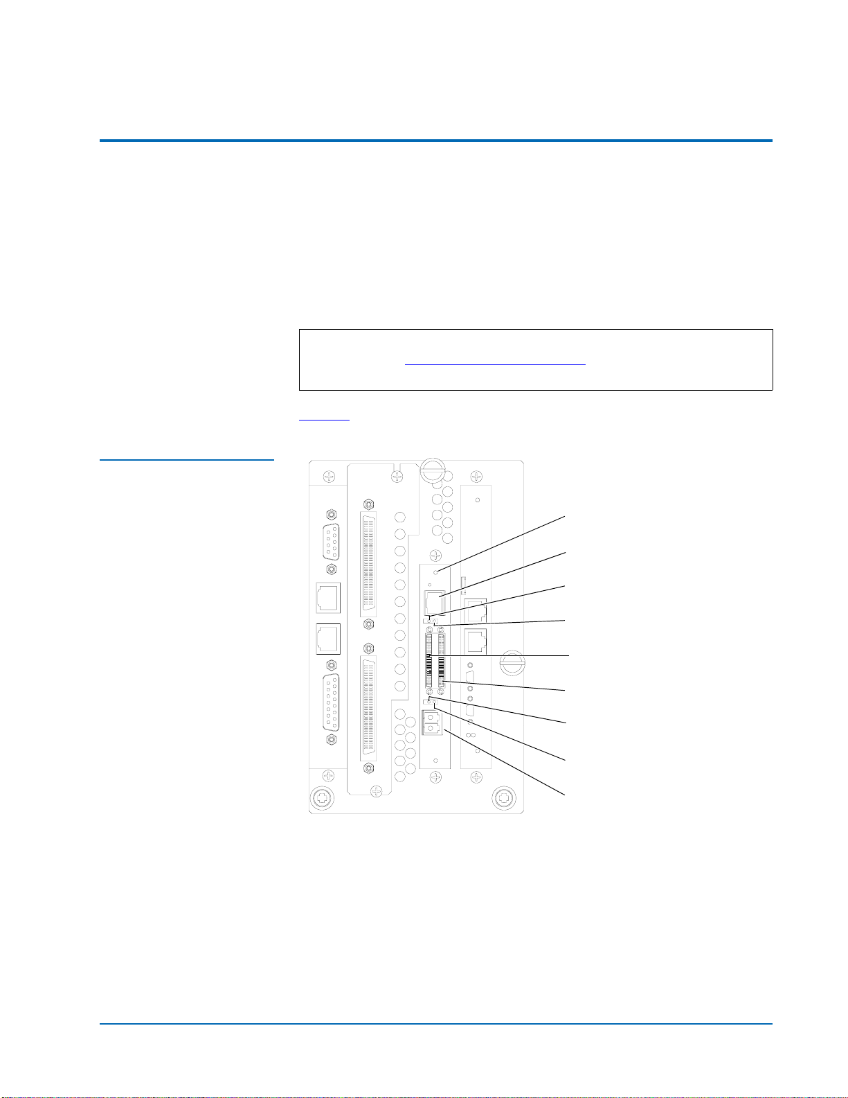
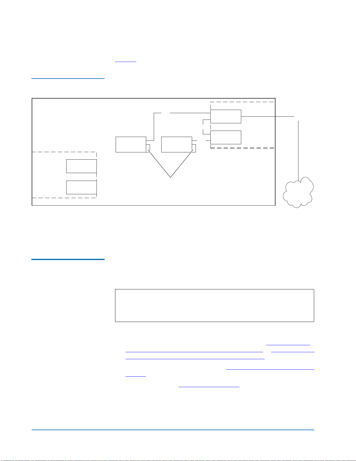
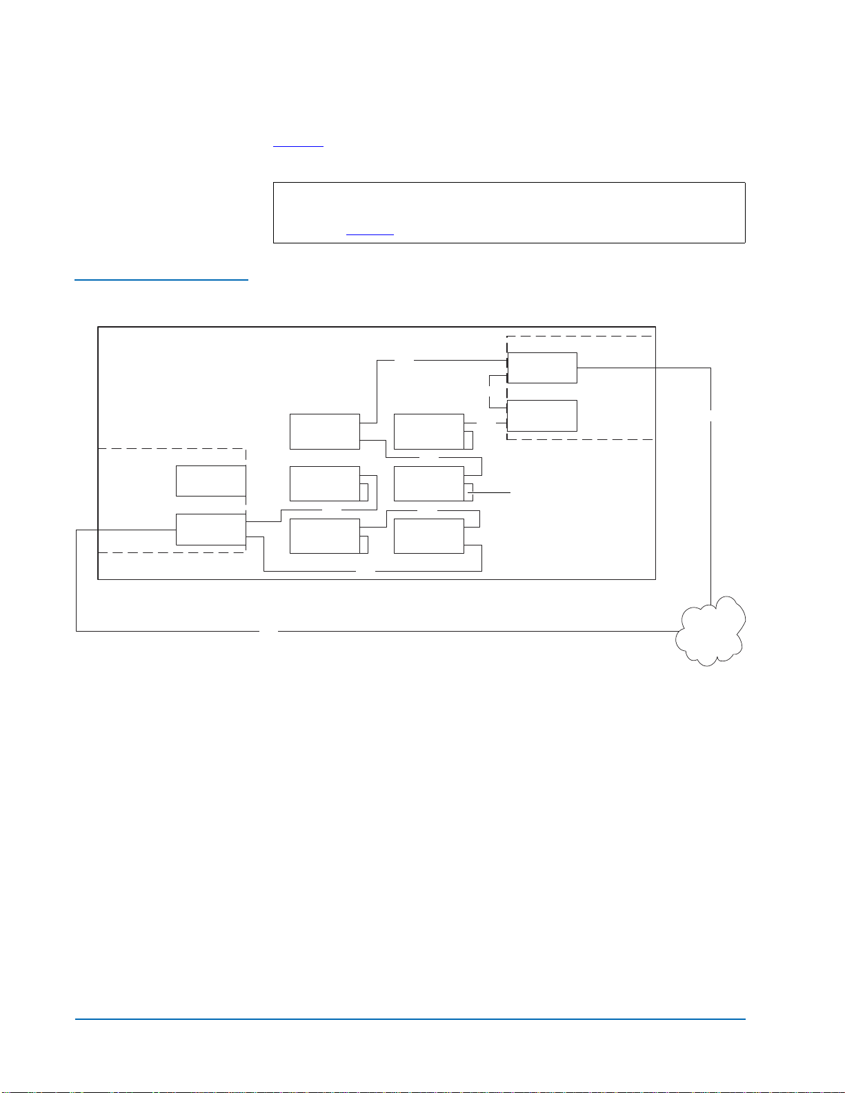
Cabling the Library for Fibre Channel 0
The cabling configuration used for the ATL M-Series library with the FC420
bridge option depends on the following factors:
• Number of tape drives installed
• Tape drive type (DLT8000, SDLT 220, SDLT 320, SDLT 600, HP LTO Gen
1, or HP LTO Gen 2)
• Number of FC420 bridges installed
• Data transfer rate of the storage area network (SAN)

Prism FC420 Bridge Option User’s Guide
Document 6473031-04, Ver. 4, Rel. 0
September 2003
Cabling the Library for Fibre Channel 5
One- and Two-Drive
Library Cabling 0If you are cabling an ATL M1500 library, or an ATL M2500 library with only
one or two tape drives, the cabling is the same regardless of drive type or
SAN. One- or two-drive libraries require only one FC420 bridge.
Figure 2 shows the cabling for a one-drive library.
Figure 2 One-Drive Library
Cabling
In a one-drive configuration (as shown in figure 2), a SCSI daisy chain is
established from one of the SCSI ports on the FC420 bridge to the SCSI
controller and then to drive 1, where the daisy chain is terminated. The SCSI
controller is included in the chain to pass SCSI commands to the robot.
The SCSI controller and drive 1 must be on the same SCSI bus because the
SCSI controller has termination disabled.
Note: HP LTO Gen 2 and SDLT 600 require 2 GB SAN connections. All
other drive types may have either a 1 GB or 2 GB SAN connection.
Drive 1
Slot for FC420
Slot for FC420
FC420
SCSI controller
SCSI
SCSI
SAN
Fibre
M1500 or M2500
Auxiliary
electronics
module
(M2500 only)
Primary
electronics
module
Terminator

Prism FC420 Bridge Option User’s Guide
Document 6473031-04, Ver. 4, Rel. 0
September 2003
6 Cabling the Library for Fibre Channel
Figure 3 shows typical cabling for a two-drive library.
Figure 3 Two-Drive Library
Cabling
In a two-drive library, the second drive (drive 2) should be connected to the
available FC420 port, creating a second SCSI bus. This utilizes the FC420
bridge fully and maximizes the communication bandwidth available to each
tape drive.
Cabling an ATL M2500
with Three or More
Drives 0
When cabling an ATL M2500 with three or more tape drives, you need to
know the type of tape drive installed in the library and the data transfer rate
of the SAN to determine the correct SCSI configuration.
To cable a library with:
• SDLT 220, SDLT 320, or HP LTO Gen 1 drives, refer to SDLT 220, SDLT
320, or HP LTO Gen 1 Drive Cabling with a 1 Gb SAN or SDLT 220, SDLT
320, or HP LTO Gen 1 Drive Cabling with a 2 Gb SAN
• SDLT 600 or HP LTO Gen 2 drives, see SDLT 600 or HP LTO Gen 2 Drive
Cabling
• DLT8000 drives, see DLT8000 Drive Cabling
Note: As with the one- and two-drive configurations, all Fibre-to-SCSI
cabling configurations must include the SCSI controller so that
SCSI commands intended for the robot are communicated
successfully.
Drive 2 Drive 1
Slot for FC420
Slot for FC420
FC420
SCSI controller
SCSI
SCSI
SCSI
SAN
Fibre
M1500 or M2500
Auxiliary
electronics
module
(M2500 only)
Primary
electronics
module
Terminator

Prism FC420 Bridge Option User’s Guide
Document 6473031-04, Ver. 4, Rel. 0
September 2003
Cabling the Library for Fibre Channel 7
SDLT 220, SDLT 320, or HP LTO Gen 1 Drive Cabling with a 1 Gb SAN 0
If an ATL M2500 containing SDLT 220, SDLT 320, or HP LTO Gen 1 drives is
connected to a 1 Gb SAN, a ratio of one tape drive per FC420 SCSI port is
recommended. This means that three- and four-drive libraries require a
second FC420 bridge, and five- and six-drive libraries require three FC420
bridges, as shown in figure 4.
Figure 4 One-Drive-Per-
FC420-Port Cabling
SDLT 220, SDLT 320, or HP LTO Gen 1 Drive Cabling with a 2 Gb SAN 0
If an ATL M2500 containing SDLT 220, SDLT 320, or HP LTO Gen 1 drives is
connected to a 2 Gb SAN, a maximum ratio of two tape drives per FC420 SCSI
port is recommended. This means that one FC420 bridge could manage up to
four tape drives, but a second FC420 bridge is required for libraries with five
or six tape drives.
Note: SDLT and LTO tape drives are sometimes referred to as
Superdrives.
Drive 2 Drive 1
Drive 4 Drive 3
Drive 6 Drive 5
FC420
FC420
FC420
SCSI controller
SCSI
SCSI
SCSI
1 Gb SAN
Fibre
Primary
electronics
module
Auxiliary
electronics
module
M2500
SCSI SCSI
SCSI
SCSI
Fibre
Fibre
Terminator

Prism FC420 Bridge Option User’s Guide
Document 6473031-04, Ver. 4, Rel. 0
September 2003
8 Cabling the Library for Fibre Channel
Figure 5 shows a six-drive library utilizing a two-drive per SCSI port cabling
scheme.
Figure 5 Two-Drive-per-
FC420-Port Cabling
Note: To increase the bandwidth available to each tape drive, install
additional FC420 bridges and use the cabling configuration shown
in figure 4.
Drive 2 Drive 1
Drive 4 Drive 3
Drive 6 Drive 5
Slot for FC420
FC420
FC420
SCSI controller
SCSI
SCSI
SCSI
SCSI
2 Gb SAN
Fibre
Primary
electronics
module
Auxiliary
electronics
module
M2500
SCSI SCSI
Fibre
SCSI
Terminator

Prism FC420 Bridge Option User’s Guide
Document 6473031-04, Ver. 4, Rel. 0
September 2003
Cabling the Library for Fibre Channel 9
SDLT 600 or HP LTO Gen 2 Drive Cabling 0
SDLT 600 and HP LTO Gen 2 drives can only be used with a 2 Gb SAN. A
ratio of one tape drive per FC420 SCSI port is recommended. This means that
three- and four-drive libraries require a second FC420 bridge, and five- and
six-drive libraries require three FC420 bridges, as shown in figure 6.
Figure 6 SDLT 600 or HP
LTO Gen 2 Drive Cabling
Drive 2 Drive 1
Drive 4 Drive 3
Drive 6 Drive 5
FC420
FC420
FC420
SCSI controller
SCSI
SCSI
SCSI
2 Gb SAN
Fibre
Primary
electronics
module
Auxiliary
electronics
module
M2500
SCSI SCSI
SCSI
SCSI
Fibre
Fibre
Terminator

Prism FC420 Bridge Option User’s Guide
Document 6473031-04, Ver. 4, Rel. 0
September 2003
10 Setting SCSI IDs
DLT8000 Drive Cabling 0
A single FC420 bridge installed in an ATL M2500 library with DLT8000 tape
drives can manage up to four drives per SCSI port. Figure 7 shows a typical
cabling configuration, with the SCSI controller and three drives on one SCSI
bus, and three drives on the other SCSI bus.
Figure 7 DLT8000 Drive
Cabling
Setting SCSI IDs 0
Use the information in table 1 to set the SCSI device addressing (SCSI IDs) for
the library.
Table 1 SCSI ID Settings
Note: To increase the bandwidth available to each drive, install
additional FC420 bridges and use the cabling configuration shown
in figure 4 or in figure 5.
Device SCSI ID Device SCSI ID
SCSI Controller 0 Drive 4 4
Drive 1 1 Drive 5 15
Drive 2 2 Drive 6 14
Drive 3 3
Drive 2 Drive 1
Drive 4 Drive 3
Drive 6 Drive 5
Slot for FC420
Slot for FC420
FC420
SCSI controller
SCSI
SCSI
SCSI
SCSI
SCSI
SCSI
SCSI
SAN
Fibre
M2500
Auxiliary
electronics
module
Primary
electronics
module
Terminator

Prism FC420 Bridge Option User’s Guide
Document 6473031-04, Ver. 4, Rel. 0
September 2003
Configuring FC420 Firmware 11
Configuring FC420 Firmware 0
Each FC420 bridge installed must be configured using the FC420 Bridge
Services software. To configure the FC420 bridge successfully, it is important
to:
• Know exactly how the SCSI cabling in the library is configured,
including:
• How many FC420 bridges are present in the library
• How many SCSI buses are present in the library
• How many SCSI devices are connected to each bus (this was
established in the previous section of this document)
• Use the FC420 Bridge Services software to create a Map file identifying
which SCSI devices are connected to which Fibre Channel ports on the
FC420 board
The major steps for manually configuring FC420 bridge firmware are:
•Setting up an Ethernet Connection
•Verifying Current FC420 Firmware
•Scanning the SCSI Busses on the Library
•Creating a Map File for the FC420
Setting up an Ethernet
Connection 0To set up an Ethernet connection between the FC420 bridge and a service PC
or other stand-alone computer equipped with Windows or Windows NT:
1Connect a Field Service Notebook to the FC420.
aTurn on the Field Service Notebook.
bDisconnect the Ethernet cable to the FC420 bridge.
Note: If you have an MC300 PMC, refer to the MC300 Prism Management
Card User’s Guide, PN 6473040, to configure your FC420 bridge (or
bridges), instead of the following steps.
Note: These major steps must be repeated for each FC420 bridge in the
library.
Note: The FC420 bridge has DHCP enabled, which searches for a server
to get an address. The DHCP server for this application is the
MC300 PMC, which is the default. If you have an MC300 PMC, do
not perform this procedure, refer to the MC300 Prism Management
Card User’s Guide, PN 6311631, for FC420 bridge administration.

Prism FC420 Bridge Option User’s Guide
Document 6473031-04, Ver. 4, Rel. 0
September 2003
12 Configuring FC420 Firmware
cPower-cycle the library.
dWait ten minutes.
2After the ten minute wait period, attach one end of a CAT-5 crossover
cable to the RJ-45 connector at the top of the FC420 bridge.
3Attach the other end of the CAT-5 crossover cable to the NIC port on the
computer.
This establishes a physical connection between the FC420 bridge and the
computer.
4Right-click the network icon on the computer’s desktop.
In some versions of Windows, this icon may be labeled Network
Neighborhood. In other versions of Windows, this icon may be labeled My
Network Places or something similar.
Windows displays a pop-up menu.
5On the pop-up menu, select Properties.
Windows displays a Network dialog box.
6Click Protocols (Windows NT) or right-click the connection and select
Properties (Windows 2000 or later).
7Double-click the TCP/IP Protocol menu item.
Windows displays the TCP/IP Properties dialog box.
8Select the option that allows you to specify an IP address.
In some version of Windows this option is shown as Specify an IP
Address. In other versions of Windows, this option is shown as Use the
Following IP Address.
The IP Address, Subnet Mask, and Gateway fields become active.
9In the IP Address field, type 10.0.0.x (where xis a number between 2 and
253).
10 In the Subnet Mask field, type 255.255.255.0.
11 Click OK until all the dialog boxes close.
Note: Make a note of the current network settings before changing
them. You will need this information if you wish to return the
computer to its previous configuration after configuring the
FC420 bridge.
Note: Do not type anything in the Gateway field.

Prism FC420 Bridge Option User’s Guide
Document 6473031-04, Ver. 4, Rel. 0
September 2003
Configuring FC420 Firmware 13
12 If you are using Windows NT, open a DOS window and type:
ipconfig/release <Enter>
ipconfig/renew <Enter>
13 Turn on the library.
14 Establish a Telnet connection to the FC420 bridge. To do this:
aStart a Telnet session from the computer desktop by selecting Start >
Run.
bIn the Run dialog box, type telnet 10.0.0.1 and then click OK.
The Telnet window opens, indicating a connection with the FC420
bridge. When you see a Ready prompt, command line mode is
available.
Verifying Current
FC420 Firmware 0To determine the current version of FC420 firmware, type info at the Ready
prompt and then press <Enter>. This command returns the firmware version
and gives the firmware revision date. Use this information to determine the if
the FC420 bridge has current firmware.
If the FC420 firmware requires updating, follow these steps:
1Contact your support representative and obtain the latest copy of the
firmware.
2If you have not done so already, establish an Ethernet connection
between the computer with the new FC420 driver and the FC420 bridge
to be updated (see Setting up an Ethernet Connection).
3On the computer, open a command prompt window.
4In the command prompt window, type ftp FC420_IP_address (where
FC420_IP_address is the IP address for the FC420 bridge) and then press
<Enter>.
5When prompted for a username, type sysadmin (or the current system
administrator ID) and then press <Enter>.
6When prompted for a password, type sysadmin (or the current system
administrator ID) and then press <Enter>.
7At the command line, type bin and then press <Enter>.
8At the command line, type put firmware_filename (where firmware_filename
is the name of the firmware file) and then press <Enter>.
Several messages appear on the screen. Finally, a success message
appears.
Note: This step is not required for other versions of Windows.
Note: Before entering the FTP command, close all prior connections
to the FC420.

Prism FC420 Bridge Option User’s Guide
Document 6473031-04, Ver. 4, Rel. 0
September 2003
14 Configuring FC420 Firmware
9Type bye or quit and then press <Enter>.
10 Power cycle the library.
Scanning the SCSI
Busses on the
Library 0
To confirm that the SCSI busses are cabled properly:
1At the Ready prompt, type scsitargets 0, and then press <Enter>.
This command scans and displays all SCSI devices found on SCSI bus 0.
2If the second SCSI port on the FC420 bridge is being utilized, wait for the
Ready prompt to reappear, then type scsitargets 1 and press <Enter>.
Creating a Map File for
the FC420 0Each FC420 bridge in the library requires a map file to identify the SCSI
devices in the library electronically connected to each Fibre Channel port on
the board.
To create the FC420 Map, perform the following steps:
1At the Ready prompt, type scsiportlist and then press <Enter>.
This command returns a list of available SCSI ports and their current
status.
2If there are no SCSI bus failures, type automap and press <Enter>.
The automap command executes.
3When the Ready prompt reappears, type saveconfiguration and press
<Enter>.
4When the Ready prompt reappears, type firmwarerestart and press <Enter>.
Making Other
Configuration
Changes 0
The preceding firmware configuration steps are mandatory to ensure
successful library operation. After completing these procedures, you may
want to make other configuration changes by issuing additional service
commands.
Service Command List 0
For your convenience, all service commands for the FC420 bridge are listed in
Prism FC420 Service Software Operation.
Using the Help Command 0
You can also obtain a list of service commands by typing help and then
pressing <Enter>.
To get more information about a particular command, type help
command_name and then press <Enter>, where command_name is the exact
name of the command about which you want information.

Prism FC420 Bridge Option User’s Guide
Document 6473031-04, Ver. 4, Rel. 0
September 2003
Prism FC420 Services Software Commands 15
Restoring the PC to
Its Original
Configuration 0
Once you have finished configuring the FC420 bridge, return the PC to its
original configuration by opening the TCP/IP Properties dialog box and return
the network settings to their original values.
Prism FC420 Services Software Commands 0
The Prism FC420 Services Software is resident on each FC420 bridge, and is
used to configure the bridge for use in the library. The software uses a
Command Line Interface (CLI).
Prism FC420 Service
Software Operation 0The Command Line Interface provides access to the FC420 services through a
set of ASCII-based command lines. Commands have four types of operation:
•Immediate—cause an immediate action; not preceded by a get or set
operation.
•Get—returns the current value of a parameter or setting. This command
may be abbreviated to “g.”
•Set—changes the value of a parameter or setting. This command may be
abbreviated “s,” and does not take effect until a SaveConfiguration command
is sent.
•Usage—if the form of an operation cannot be determined, it is assumed to
be the “Usage” form and a brief help message is displayed.
The commands are not case sensitive.
Decimal numbers may be entered as raw numerical input, such as 123.
Octal numbers must be preceded by the number 0, for example 0713.
Hexadecimal numbers must be preceded by the C-style of 0x prefix, such as
9x1FA4.
Quoted strings are treated as a single parameter for any command which
expects character input, regardless of space in the string.
Several non-immediate commands require a SaveConfiguration before their
modified parameters take effect. When such a command is executed an
asterisk appears next to the command line prompt.
Command Syntax 0The following is a list of syntax used to describe command lines:
• [ ] indicates required entry
• < > indicates optional entry
• | indicates choose one entry

Prism FC420 Bridge Option User’s Guide
Document 6473031-04, Ver. 4, Rel. 0
September 2003
16 Prism FC420 Services Software Commands
List of Abbreviations 0The following is a list of abbreviations used to describe command lines:
• fp Fibre Channel port number (0)
• fl Fibre Channel LUN (0 - 31)
•sb SCSIbusnumber(0-1)
• st SCSI target ID (1 - 15)
•sl SCSILUN(0-7)
Command Listing 0Table 2 lists the currently available Prism FC420 Services Software
commands.
Table 2 Prism FC420
Services Commands
Command Description Default Syntax
AutoMap
(Immediate)
Automatically maps all currently
operational SCSI devices attached to the
FC420 bridge.
Issue an FCPortList and a SCSIPortList
command before issuing an AutoMap
command because AutoMap ignores
devices attached to a non-operational
SCSI bus and assigns devices to a non-
operational Fibre Channel port.
automap
automap [fp]
BootFibreDelay Selects/displays the boot fibre delay (in
seconds).
0 set bootfibredelay [0 | 15 | 30]
get bootfibredelay
BootScan Enables/disables the boot scan feature.
This feature provides dynamic mapping
of SCSI devices to fibre port/LUN
combinations via a SCSI port at boot
time.
enabled set bootscan [enabled |
disabled]
get bootscan
BootScanPorts Selects/displays the ports to be used for
a boot scan.
all set bootscanports [fp |all | auto]
get bootscanports
ClearEvent
(Immediate)
Clears the contents of the event log. clearevent
DhcpFixedDelay Selects/displays the delay interval (in
seconds) between DHCP client requests.
5 set dhcpfixeddelay [0 | 15 | 30]
get dhcpfixeddelay

Prism FC420 Bridge Option User’s Guide
Document 6473031-04, Ver. 4, Rel. 0
September 2003
Prism FC420 Services Software Commands 17
DispEvent Sets the switches that control the
filtering performed when displaying
events.
set dispevent [subsystem]
[event_level] [status]
get dispevent
Switches have the following settings:
[subsystem] switch: mask that controls which subsystem events are
displayed. The mask is a byte value with the following bit patterns
corresponding to the currently supported subsystems:
0x01 FCP Processor/i960 Interaction
0x02 SCSI Processor/i960 Interaction
0x04 Ethernet (Future)
0x08 Extended copy
0x20 NVRAM & Flash
0x40 ECC & Parity
0x80 Performance
To display events from several different subsystems, use a mask
value equal to the logical OR of the corresponding subsystem
values. To display events from all subsystems enter the value 0x7F
for the mask.
0x00
[event_level] switch: mask that controls what reporting level events are
displayed. The mask is a byte value with the following bit patterns
corresponding to the currently supported reporting levels:
0x01 Info; general information
0x02 Warning; unexpected situation/condition
0x04 Critical; operation limited/curtailed
0x08 Failure; hard failure
0x10 Other; otherwise not categorized
0x20 Debug; tracking events
To display events from several different reporting levels, use a mask
value equal to the logical OR of the corresponding reporting levels.
To display events for all reporting levels enter the value 0x7F for the
mask.
0x00
[status] switch: This switch has the following two values which
correspond to the status of the events to be displayed:
all All events, regardless of their status values are displayed.
ngood Only events with a status other than good are displayed.
ngood
DispFcPortDB
(Immediate)
Displays the contents of the specified
Fibre port’s internal database.
dispfcportdb<fp>
Command Description Default Syntax

Prism FC420 Bridge Option User’s Guide
Document 6473031-04, Ver. 4, Rel. 0
September 2003
18 Prism FC420 Services Software Commands
DisplayEvent
(Immediate)
Displays the current contents of the
event log. The log is filtered by the
current switch settings as described in
the DispEvent section. If the optional all is
selected, the display filtering is
temporarily suspended and all logged
events are displayed.
displayevent <all>
EccLog Resets/displays the ECC error statistics
for the FC420 bridge. The get command
displays the statistics; the set command
resets the statistic counters to zero.
set ecclog clear
get ecclog
ErrorLog Resets/displays the error logs for the
FC420 bridge. The get command
displays the logs; the set command
resets the logs to zero.
set errorlog clear
get errorlog
EthernetSpeed Sets/displays the Ethernet speed of the
Fibre connection. If auto is selected, the
current speed of the connection is
indicated in parentheses in the response
to the get ethernetspeed command.
auto set ethernetspeed [10 | 100 |
auto]
get ethernetspeed
Exit
(Immediate)
Exits the current Telnet command line
interface (CLI) session). This command
has no effect during a serial or in-band
CLI session.
exit
FcAck0 Specifies whether ACK0 or ACK1 will
be returned in response to a Class 2
Fibre Channel data frame or sequence.
When enabled, this option sends ACK0;
when disabled, this option sends ACK1.
disabled set fcack0 [enabled | disabled]
get fcack0
FcClass2 Specifies whether the FC420 bridge will
support Fibre Channel Class 2
(Multiplexed) or Class 3 service.
disabled set fcclass2 [enabled |
disabled]
get fcclass2
FcConnMode Sets/displays the Fibre Channel
connection mode for the FC420 to
arbitrated loop or point-to-point.
Loop-ptp and ptp-loop will auto-negotiate
starting with the first topology type.
ptp-loop set fcconnmode [loop | ptp |
loop-ptp | ptp-loop]
get fcconnmode
FcDataRate Sets/displays the data rate (in Gb/s) at
which the FC420 bridge will operate.
auto set fcdatarate [1gb | 2gb | auto]
get fcdatarate
FcFairArb Turns on or off the FC-AL arbitration
fairness. Applies to all three Fibre
Channel ports on each board.
enabled set fcfairarb [enabled |
disabled]
get fcfairarb
Command Description Default Syntax

Prism FC420 Bridge Option User’s Guide
Document 6473031-04, Ver. 4, Rel. 0
September 2003
Prism FC420 Services Software Commands 19
FcFullDuplex Enables/disables full duplex
communication between the FC420
bridge and other Fibre Channel devices.
enabled set fcfullduplex [enabled |
disabled]
get fcfullduplex
FcHard Enables/disables Fibre Channel hard
address assignment. Under soft
addressing the FC420 loop address is
assigned during loop initialization.
disabled set fchard [enabled | disabled]
get fchard
FcHardAddress Sets/displays the value used as the FC-
AL hard address.
FC port 0
0x03 set fchardaddress [fp
[address]]
get fchardaddress [fp]
FcInitiator Enables/disables the initiator function
of the FC420 bridge on the Fibre channel
network.
disabled set fcinitiator [enabled |
disabled]
get fcinitiator
FcPortList
(Immediate)
Lists the available Fibre Channel ports
and their current status.
fcportlist
Fcp2 Enables/disables the FC420 bridge’s
compliance with the FCP-2 Fibre
Channel specification.
enabled set fcp2 [enabled | disabled]
get fcp2
Fcp2Conf Enables/disables the FC420 bridge’s
capability to request FCP_CONF IUs.
This option is valid only when the fcp2
command is also enabled.
enabled set fcpconf [enabled | disabled]
get fcp2conf
Fcp2CRN Enables/disables the FC420 bridge’s
capability to accept CRNs for precise
delivery of SCSI commands. This option
is only valid when the fcp2 command is
also enabled.
disabled set fcpcrn [enabled | disabled]
get fcp2crn
FcSCSIBusyStatus Specify the SCSI status value returned
when the FC420 is unable to accept a
SCSI command due to a temporary lack
of internal resources.
BUSY set fcscsibusystatus [busy |
qfull]
getfcscsibusystatus
FcTargets
(Immediate)
Provides the node name, Fibre LUN,
and inquiry data for every Fibre
Channel target device visible to an
FC420 bridge operating in initiator
mode.
fctargets <fp>
Command Description Default Syntax

Prism FC420 Bridge Option User’s Guide
Document 6473031-04, Ver. 4, Rel. 0
September 2003
20 Prism FC420 Services Software Commands
FcWWName Sets/displays the current World Wide
Name (WWN) of the Fibre Channel
interface referenced. Each Fibre port has
a unique WWN. The least significant 6
bits of the WWN are used as the
Ethernet MAC address.
The set variant of the command allows
the user to change the last three bytes of
each WWN. Please note, however, that
the most significant bit of the three bytes
must be 1 in order to provide WWN
verification. Also note that the last bit of
each WWN may only be assigned one of
the following values: 0, 4, 8, or C for port
0; 1, 5, 9, or D for port 1; and 2, 6, A, or E
for port 2.
Fabric and loop operation is
unpredictable if duplicate WWNs are
used.
10 00 0x,
where x
is the
Fibre
port
number.
set fcwwname [portnumber
[0xnn 0xnn 0xnn]]
get fcwwname [portnumber]
FibreBridgeModel Reports the specific FC420 model
information.
get fibrebridgemodel
FibreBridgeName Specify the 8-character name assigned to
the FC420 bridge.
set fibrebridgename [value]
get fibrebridgename
FibreBridgeTargetLUN Specify the soft target LUN used by the
FC420 when addressed by the host. This
LUN is taken from NVRAM.
disabled set FibreBridgeTargetLUN [fp]
[fl] | [disabled] ]
FirmwareRestart
(Immediate)
Reboots the FC420 firmware. firmwarerestart
Help
(Immediate)
Displays a list of available commands.
When the optional command name is
present, detailed command-specific
information is displayed.
help [command name]
IdentifyFibreBridge Causes the Ready LED on the FC420
board to blink continuously until
disabled.
disabled set identifyfibrebridge [enabled
| disabled]
get identifyfibrebridge
Info
(Immediate)
Displays version numbers and other
product information for key
components within the FC420.
info
IPAddress Sets/displays the current IP address of
the FC420 bridge. If the ipdhcp command
is enabled, the get command reports the
current IP address assigned by the
nameserver.
10.0.0.1 set ipaddress xxx.xxx.xxx.xxx
get ipaddress
Command Description Default Syntax
Other manuals for FC420
1
Table of contents
Popular Accessories manuals by other brands

OHM ELECTRIC
OHM ELECTRIC Cool Cabi OCA-S350BCD-A200 instruction manual

wtw
wtw CN 500 DIN operating manual

PCB Piezotronics
PCB Piezotronics M215B Installation and operating manual

Rohde & Schwarz
Rohde & Schwarz R&S NRQ6 Getting started

Harvil
Harvil KB-1 product manual

Olympus
Olympus AS2400 - AS Transcription Kit instructions

Borotto
Borotto Lumia 8 Translation of the original instructions

Johnson Controls
Johnson Controls NS Series installation instructions

Carefree of Colorado
Carefree of Colorado Mirage Service manual

CHIEF
CHIEF DGP32 installation instructions

Helios
Helios AIR1/KWL-CO2 0-10V Installation and operating instructions

Audiovox
Audiovox 1285503 installation instructions