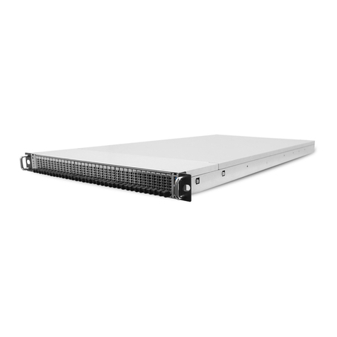
Quantum ActiveScale X100 User manual

ActiveScale
X100 Rackless Instalation Guide
6-68841-03, Rev. A
with ActiveScale OS 6.0.2 software

ActiveScale™ OS X100 Rackless Installation Guide
2
Quantum ActiveScale™ OS X100 Rackless Installation Guide, 6-68841-03, October 2021, Product of USA.
Quantum Corporation provides this publication “as is” without warranty of any kind, either express or implied, including but not limited to the
implied warranties of merchantability or fitness for a particular purpose. Quantum Corporation may revise this publication from time to time
without notice.
COPYRIGHT STATEMENT
© 2021 Quantum Corporation. All rights reserved. Your right to copy this manual is limited by copyright law. Making copies or adaptations
without prior written authorization of Quantum Corporation is prohibited by law and constitutes a punishable violation of the law. ActiveScale,
DXi, DXi Accent, FlexSync, FlexTier, iLayer, Lattus, Quantum, The Quantum Logo, QXS, Scalar, StorNext, SuperLoader, Vision, and Xcellis
are either registered trademarks or trademarks of Quantum Corporation and its affiliates in the United States and/or other countries. All other
trademarks are the property of their respective owners. Quantum specifications are subject to change.
TRADEMARK STATEMENT
Quantum is/are a registered trademark of Quantum Corporation and ActiveScale is a trademark of Quantum Corporation and its affiliates in the
United States and/or other countries. Amazon S3, Amazon Simple Storage Services, and Amazon AWS S3 are trademarks of Amazon.com, Inc. or
its affiliates in the United States and/or other countries. BitDynamics® and BitSpread® are trademarks of Western Digital Corporation. Other
trademarks are the property of their respective owners. References in this publication to Quantum-branded products, programs, or services do not
imply that they will be made available in all countries. Product specifications provided are sample specifications and do not constitute a
warranty. Actual specifications for unique part numbers may vary. Please visit the Support section of our website https://quantum.com/support for
additional information on product specifications.

ActiveScale™ OS X100 Rackless Installation Guide Contents
3
Contents
Contents . . . . . . . . . . . . . . . . . . . . . . . . . . . . . . . . . . . . . . . . . . . . . . . . . . . . . . . . . . . . . . . . . . . . 3
List of tables . . . . . . . . . . . . . . . . . . . . . . . . . . . . . . . . . . . . . . . . . . . . . . . . . . . . . . . . . . . . . . . . . 8
List of figures . . . . . . . . . . . . . . . . . . . . . . . . . . . . . . . . . . . . . . . . . . . . . . . . . . . . . . . . . . . . . . . 11
1 Rackless ActiveScale X100 product overview . . . . . . . . . . . . . . . . . . . . . . . . . . . . . . . . . . . . . 15
1.1 About shipping pallets and boxes . . . . . . . . . . . . . . . . . . . . . . . . . . . . . . . . . . . . . . . 16
1.2 System specification summary . . . . . . . . . . . . . . . . . . . . . . . . . . . . . . . . . . . . . . . . . 18
1.3 Summary of installation phases . . . . . . . . . . . . . . . . . . . . . . . . . . . . . . . . . . . . . . . . . 20
2 Preparing the rack . . . . . . . . . . . . . . . . . . . . . . . . . . . . . . . . . . . . . . . . . . . . . . . . . . . . . . . . . . . 29
2.1 Verifying rack requirements . . . . . . . . . . . . . . . . . . . . . . . . . . . . . . . . . . . . . . . . . . . 30
2.2 Servicing space requirement . . . . . . . . . . . . . . . . . . . . . . . . . . . . . . . . . . . . . . . . . . . 32
2.3 PDU considerations . . . . . . . . . . . . . . . . . . . . . . . . . . . . . . . . . . . . . . . . . . . . . . . . . . 32
2.4 System serial number . . . . . . . . . . . . . . . . . . . . . . . . . . . . . . . . . . . . . . . . . . . . . . . . . 33
3 Installing the Storage Enclosure Basics. . . . . . . . . . . . . . . . . . . . . . . . . . . . . . . . . . . . . . . . . . . 35
3.1 Identification of assembled Storage Enclosure Basic . . . . . . . . . . . . . . . . . . . . . . . . 37
3.2 About assembling the Storage Enclosure Basic . . . . . . . . . . . . . . . . . . . . . . . . . . . . . 37
3.2.1 Unpacking a Storage Enclosure Basic . . . . . . . . . . . . . . . . . . . . . . . . . . . . . . . 38
3.3 Installing the rail kit . . . . . . . . . . . . . . . . . . . . . . . . . . . . . . . . . . . . . . . . . . . . . . . . . . 39
3.4 Installing the chassis . . . . . . . . . . . . . . . . . . . . . . . . . . . . . . . . . . . . . . . . . . . . . . . . . 44
3.5 Installing the sleds . . . . . . . . . . . . . . . . . . . . . . . . . . . . . . . . . . . . . . . . . . . . . . . . . . . 49
3.6 Installing the rear fans . . . . . . . . . . . . . . . . . . . . . . . . . . . . . . . . . . . . . . . . . . . . . . . . 54
3.7 Adjusting the cord retention bale . . . . . . . . . . . . . . . . . . . . . . . . . . . . . . . . . . . . . . . . 56
3.8 Installing the I/O module . . . . . . . . . . . . . . . . . . . . . . . . . . . . . . . . . . . . . . . . . . . . . . 57
3.9 Connecting power cables . . . . . . . . . . . . . . . . . . . . . . . . . . . . . . . . . . . . . . . . . . . . . . 62
3.10 Sanity check . . . . . . . . . . . . . . . . . . . . . . . . . . . . . . . . . . . . . . . . . . . . . . . . . . . . . . . 66
3.11 Assemble the remaining Storage Enclosure Basics . . . . . . . . . . . . . . . . . . . . . . . . . 66
4 Installing Storage Nodes . . . . . . . . . . . . . . . . . . . . . . . . . . . . . . . . . . . . . . . . . . . . . . . . . . . . . . 69
4.1 Installing the Storage Nodes . . . . . . . . . . . . . . . . . . . . . . . . . . . . . . . . . . . . . . . . . . . 70
4.2 Connecting SAS cables . . . . . . . . . . . . . . . . . . . . . . . . . . . . . . . . . . . . . . . . . . . . . . . 74
4.3 Connecting power cables to the Storage Nodes . . . . . . . . . . . . . . . . . . . . . . . . . . . . . 75
5 Installing System Nodes . . . . . . . . . . . . . . . . . . . . . . . . . . . . . . . . . . . . . . . . . . . . . . . . . . . . . . 77
5.1 Installing the System Nodes . . . . . . . . . . . . . . . . . . . . . . . . . . . . . . . . . . . . . . . . . . . 78
5.2 Connecting power cables to the System Nodes . . . . . . . . . . . . . . . . . . . . . . . . . . . . . 82
6 Installing System Interconnects . . . . . . . . . . . . . . . . . . . . . . . . . . . . . . . . . . . . . . . . . . . . . . . . . 83
6.1 Installing the System Interconnects . . . . . . . . . . . . . . . . . . . . . . . . . . . . . . . . . . . . . 84
6.2 Cabling the System Interconnects . . . . . . . . . . . . . . . . . . . . . . . . . . . . . . . . . . . . . . . 89

ActiveScale™ OS X100 Rackless Installation Guide Contents
4
6.2.1 Cabling the Storage Nodes . . . . . . . . . . . . . . . . . . . . . . . . . . . . . . . . . . . . . . . . 89
6.2.2 Cabling the System Nodes . . . . . . . . . . . . . . . . . . . . . . . . . . . . . . . . . . . . . . . . 93
6.3 Connecting the ActiveScale X100 to the customer network . . . . . . . . . . . . . . . . . . . 96
6.3.1 User provided cables . . . . . . . . . . . . . . . . . . . . . . . . . . . . . . . . . . . . . . . . . . . . . 97
6.3.1.1 Installing SFP+ transceivers . . . . . . . . . . . . . . . . . . . . . . . . . . . . . . . . . . 97
7 Installing the Management Interconnect . . . . . . . . . . . . . . . . . . . . . . . . . . . . . . . . . . . . . . . . . . 99
7.1 Installing the Management Interconnect . . . . . . . . . . . . . . . . . . . . . . . . . . . . . . . . . 100
7.2 Cabling the Management Interconnect . . . . . . . . . . . . . . . . . . . . . . . . . . . . . . . . . . 102
7.3 Connecting a power cable to the Management Interconnect . . . . . . . . . . . . . . . . . . 104
8 Powering the ActiveScale X100 . . . . . . . . . . . . . . . . . . . . . . . . . . . . . . . . . . . . . . . . . . . . . . . 105
8.1 About PDU requirements . . . . . . . . . . . . . . . . . . . . . . . . . . . . . . . . . . . . . . . . . . . . . 106
8.2 Powering on the ActiveScale X100 components . . . . . . . . . . . . . . . . . . . . . . . . . . . 106
9 Final steps . . . . . . . . . . . . . . . . . . . . . . . . . . . . . . . . . . . . . . . . . . . . . . . . . . . . . . . . . . . . . . . . 109
9.1 Tidying up . . . . . . . . . . . . . . . . . . . . . . . . . . . . . . . . . . . . . . . . . . . . . . . . . . . . . . . . 109
10 System bringup . . . . . . . . . . . . . . . . . . . . . . . . . . . . . . . . . . . . . . . . . . . . . . . . . . . . . . . . . . . 111
10.1 What to bring with you to the data center . . . . . . . . . . . . . . . . . . . . . . . . . . . . . . . 111
10.2 Single site deployments . . . . . . . . . . . . . . . . . . . . . . . . . . . . . . . . . . . . . . . . . . . . . 112
10.2.1 Summary of workflow . . . . . . . . . . . . . . . . . . . . . . . . . . . . . . . . . . . . . . . . . 112
10.2.2 Run the pre-login configuration wizard (single site version) . . . . . . . . . . . . 112
10.2.3 Connect the system to your networks . . . . . . . . . . . . . . . . . . . . . . . . . . . . . . 118
10.2.4 Run the post-login configuration wizard (single site version) . . . . . . . . . . . 120
10.3 Multi-site deployments . . . . . . . . . . . . . . . . . . . . . . . . . . . . . . . . . . . . . . . . . . . . . 130
10.3.1 Summary of workflow . . . . . . . . . . . . . . . . . . . . . . . . . . . . . . . . . . . . . . . . . 131
10.3.2 Do additional setup for a multi-site deployment . . . . . . . . . . . . . . . . . . . . . 131
10.3.2.1 Obtain cables and transceivers . . . . . . . . . . . . . . . . . . . . . . . . . . . . . . . 131
10.3.2.2 Create the required networks at each site . . . . . . . . . . . . . . . . . . . . . . 132
10.3.2.3 Check data paths and latency . . . . . . . . . . . . . . . . . . . . . . . . . . . . . . . . 133
10.3.2.4 Create uplinks . . . . . . . . . . . . . . . . . . . . . . . . . . . . . . . . . . . . . . . . . . . 134
10.3.3 Connect the system to your networks . . . . . . . . . . . . . . . . . . . . . . . . . . . . . . 136
10.3.4 Run the pre-login configuration wizard (multi-site version) . . . . . . . . . . . . 137
10.3.5 Run the post-login configuration wizard (multi-site version) . . . . . . . . . . . 148
10.4 Verify system status . . . . . . . . . . . . . . . . . . . . . . . . . . . . . . . . . . . . . . . . . . . . . . . . 158
10.5 Troubleshooting . . . . . . . . . . . . . . . . . . . . . . . . . . . . . . . . . . . . . . . . . . . . . . . . . . 160
11 Installing rack seal kits. . . . . . . . . . . . . . . . . . . . . . . . . . . . . . . . . . . . . . . . . . . . . . . . . . . . . . 163
11.1 Installing the rack seal plate . . . . . . . . . . . . . . . . . . . . . . . . . . . . . . . . . . . . . . . . . . 164
12 Installing scale up kits . . . . . . . . . . . . . . . . . . . . . . . . . . . . . . . . . . . . . . . . . . . . . . . . . . . . . . 167
12.1 Installing sled columns as part of scale up . . . . . . . . . . . . . . . . . . . . . . . . . . . . . . 168

ActiveScale™ OS X100 Rackless Installation Guide Contents
5
12.2 Provisioning the newly added sleds on a single site system . . . . . . . . . . . . . . . . . 172
12.3 Provisioning the newly added sleds on a multi-site system- . . . . . . . . . . . . . . . . . . . 176
13 Installing scale out kits . . . . . . . . . . . . . . . . . . . . . . . . . . . . . . . . . . . . . . . . . . . . . . . . . . . . . 182
13.1 Hardware steps . . . . . . . . . . . . . . . . . . . . . . . . . . . . . . . . . . . . . . . . . . . . . . . . . . . . 183
13.2 Parts Required for Scale Out . . . . . . . . . . . . . . . . . . . . . . . . . . . . . . . . . . . . . . . . . 183
13.2.1 Additional Parts Required for Multi-Site Configuration . . . . . . . . . . . . . . . 183
13.3 Connecting the Cables Between the Systems . . . . . . . . . . . . . . . . . . . . . . . . . . . . 184
13.3.1 Cabling Two Systems . . . . . . . . . . . . . . . . . . . . . . . . . . . . . . . . . . . . . . . . . . 185
13.4 Cabling Three Systems . . . . . . . . . . . . . . . . . . . . . . . . . . . . . . . . . . . . . . . . . . . . . 185
13.5 Opening Interconnect Ports . . . . . . . . . . . . . . . . . . . . . . . . . . . . . . . . . . . . . . . . . . 186
13.6 Additional steps for multi-site configurations . . . . . . . . . . . . . . . . . . . . . . . . . . . . 188
13.6.1 Software steps . . . . . . . . . . . . . . . . . . . . . . . . . . . . . . . . . . . . . . . . . . . . . . . . 189
13.6.2 Post-requisites . . . . . . . . . . . . . . . . . . . . . . . . . . . . . . . . . . . . . . . . . . . . . . . . 194
14 Installing System Expansion Node kits . . . . . . . . . . . . . . . . . . . . . . . . . . . . . . . . . . . . . . . . . 195
14.1 System Expansion Node kit requirements . . . . . . . . . . . . . . . . . . . . . . . . . . . . . . . 196
14.1.1 Public Network IP address requirements . . . . . . . . . . . . . . . . . . . . . . . . . . . 196
14.1.2 Multi-site deployment requirements . . . . . . . . . . . . . . . . . . . . . . . . . . . . . . . 196
14.1.3 Rack requirements . . . . . . . . . . . . . . . . . . . . . . . . . . . . . . . . . . . . . . . . . . . . 196
14.1.4 PDU requirements . . . . . . . . . . . . . . . . . . . . . . . . . . . . . . . . . . . . . . . . . . . . . 196
14.1.4.1 PDU requirements for Racked systems . . . . . . . . . . . . . . . . . . . . . . . . 196
14.2 Unpacking System Expansion Node kits . . . . . . . . . . . . . . . . . . . . . . . . . . . . . . . . 196
14.3 Installing System Expansion Node kits . . . . . . . . . . . . . . . . . . . . . . . . . . . . . . . . . 197
14.3.1 Installing the 1U rail kit . . . . . . . . . . . . . . . . . . . . . . . . . . . . . . . . . . . . . . . . 198
14.3.2 Installing a System Expansion Node into the rack . . . . . . . . . . . . . . . . . . . . 201
14.4 Connecting the System Expansion Node kit networking cables . . . . . . . . . . . . . . 201
14.5 Installing System Expansion Node kits in multi-site systems . . . . . . . . . . . . . . . . 202
14.6 Installing the System Expansion Node PDU kit . . . . . . . . . . . . . . . . . . . . . . . . . . 203
14.6.1 Re-balancing the PDUs . . . . . . . . . . . . . . . . . . . . . . . . . . . . . . . . . . . . . . . . . 203
14.6.1.1 Three-phase across two PDUs . . . . . . . . . . . . . . . . . . . . . . . . . . . . . . . 204
14.6.1.2 Three-phase across three PDUs . . . . . . . . . . . . . . . . . . . . . . . . . . . . . . 205
14.6.2 Programming the PDUs . . . . . . . . . . . . . . . . . . . . . . . . . . . . . . . . . . . . . . . . 207
14.6.2.1 Connecting to the PDU with a serial port . . . . . . . . . . . . . . . . . . . . . . 207
14.6.2.2 Connecting to the PDU with an Ethernet port . . . . . . . . . . . . . . . . . . . 208
14.6.2.3 Logging into the PDU Firmware CLI . . . . . . . . . . . . . . . . . . . . . . . . . 208
14.6.2.4 Three-phase PDU programming with three PDUs . . . . . . . . . . . . . . . 209
14.7 Programming the System Interconnects . . . . . . . . . . . . . . . . . . . . . . . . . . . . . . . . 213
14.8 Powering on the System Expansion Node . . . . . . . . . . . . . . . . . . . . . . . . . . . . . . . 215
14.9 Software steps for adding a System Expansion Node kit . . . . . . . . . . . . . . . . . . . 215

ActiveScale™ OS X100 Rackless Installation Guide Contents
6
15 System specifications. . . . . . . . . . . . . . . . . . . . . . . . . . . . . . . . . . . . . . . . . . . . . . . . . . . . . . . 222
15.1 System specification summary . . . . . . . . . . . . . . . . . . . . . . . . . . . . . . . . . . . . . . . 223
15.2 Hard disk drive specifications . . . . . . . . . . . . . . . . . . . . . . . . . . . . . . . . . . . . . . . . 224
15.3 Management Interconnect specifications . . . . . . . . . . . . . . . . . . . . . . . . . . . . . . . . 226
15.4 PDU specifications . . . . . . . . . . . . . . . . . . . . . . . . . . . . . . . . . . . . . . . . . . . . . . . . 227
15.4.1 Power cords . . . . . . . . . . . . . . . . . . . . . . . . . . . . . . . . . . . . . . . . . . . . . . . . . . 228
15.5 Rack specifications . . . . . . . . . . . . . . . . . . . . . . . . . . . . . . . . . . . . . . . . . . . . . . . . 228
15.6 Solid state drive specifications . . . . . . . . . . . . . . . . . . . . . . . . . . . . . . . . . . . . . . . 230
15.7 Storage Enclosure Basic specifications . . . . . . . . . . . . . . . . . . . . . . . . . . . . . . . . . 230
15.8 Storage Node specifications . . . . . . . . . . . . . . . . . . . . . . . . . . . . . . . . . . . . . . . . . . 231
15.9 System Interconnect specifications . . . . . . . . . . . . . . . . . . . . . . . . . . . . . . . . . . . . 231
15.10 System Node specifications . . . . . . . . . . . . . . . . . . . . . . . . . . . . . . . . . . . . . . . . . 232
16 Recommended torque of machined fasteners . . . . . . . . . . . . . . . . . . . . . . . . . . . . . . . . . . . . 233
17 About the cord retention bale. . . . . . . . . . . . . . . . . . . . . . . . . . . . . . . . . . . . . . . . . . . . . . . . . 235
17.1 Adjusting the cord retention bale . . . . . . . . . . . . . . . . . . . . . . . . . . . . . . . . . . . . . . 235
18 Host connectivity for the Storage Enclosure Basic . . . . . . . . . . . . . . . . . . . . . . . . . . . . . . . . 239
19 About ActiveScale X100 racks . . . . . . . . . . . . . . . . . . . . . . . . . . . . . . . . . . . . . . . . . . . . . . . 241
19.1 Rack requirements . . . . . . . . . . . . . . . . . . . . . . . . . . . . . . . . . . . . . . . . . . . . . . . . . 242
19.2 Airflow considerations . . . . . . . . . . . . . . . . . . . . . . . . . . . . . . . . . . . . . . . . . . . . . . 242
20 PDU specifications . . . . . . . . . . . . . . . . . . . . . . . . . . . . . . . . . . . . . . . . . . . . . . . . . . . . . . . . 245
20.1 PDU requirements, common . . . . . . . . . . . . . . . . . . . . . . . . . . . . . . . . . . . . . . . . . 246
20.2 Mechanical requirements . . . . . . . . . . . . . . . . . . . . . . . . . . . . . . . . . . . . . . . . . . . . 247
20.2.1 Redundancy . . . . . . . . . . . . . . . . . . . . . . . . . . . . . . . . . . . . . . . . . . . . . . . . . 247
20.2.2 Mounting in system . . . . . . . . . . . . . . . . . . . . . . . . . . . . . . . . . . . . . . . . . . . 247
20.2.3 Workmanship and finish . . . . . . . . . . . . . . . . . . . . . . . . . . . . . . . . . . . . . . . . 247
20.3 Monitoring . . . . . . . . . . . . . . . . . . . . . . . . . . . . . . . . . . . . . . . . . . . . . . . . . . . . . . . 248
20.3.1 Local monitoring . . . . . . . . . . . . . . . . . . . . . . . . . . . . . . . . . . . . . . . . . . . . . . 248
20.3.2 Parameters monitored . . . . . . . . . . . . . . . . . . . . . . . . . . . . . . . . . . . . . . . . . . 248
20.3.3 Communication interface . . . . . . . . . . . . . . . . . . . . . . . . . . . . . . . . . . . . . . . 248
20.4 Miscellaneous requirements . . . . . . . . . . . . . . . . . . . . . . . . . . . . . . . . . . . . . . . . . 248
20.4.0.1 Best practices for power sequencing . . . . . . . . . . . . . . . . . . . . . . . . . . 248
20.4.1 Safety . . . . . . . . . . . . . . . . . . . . . . . . . . . . . . . . . . . . . . . . . . . . . . . . . . . . . . 249
20.4.2 Electromagnetic compatibility . . . . . . . . . . . . . . . . . . . . . . . . . . . . . . . . . . . 249
20.4.3 Environmental . . . . . . . . . . . . . . . . . . . . . . . . . . . . . . . . . . . . . . . . . . . . . . . . 249
20.5 Example configurations . . . . . . . . . . . . . . . . . . . . . . . . . . . . . . . . . . . . . . . . . . . . . 249
20.5.1 3-phase delta, 208V, 24A, NA, Japan . . . . . . . . . . . . . . . . . . . . . . . . . . . . . . 250
20.5.2 3-phase delta, 208V, 48A, NA . . . . . . . . . . . . . . . . . . . . . . . . . . . . . . . . . . . 252
20.5.3 3-phase WYE, 230V, 16A, Europe, Global . . . . . . . . . . . . . . . . . . . . . . . . . 254

ActiveScale™ OS X100 Rackless Installation Guide Contents
7
20.5.4 Single-phase 220V, 24A, NA . . . . . . . . . . . . . . . . . . . . . . . . . . . . . . . . . . . . 256
20.5.5 1-phase 230V, 32A, Europe, global . . . . . . . . . . . . . . . . . . . . . . . . . . . . . . . 258
21 How to read cable labels . . . . . . . . . . . . . . . . . . . . . . . . . . . . . . . . . . . . . . . . . . . . . . . . . . . . 261
21.1 Cable mapping . . . . . . . . . . . . . . . . . . . . . . . . . . . . . . . . . . . . . . . . . . . . . . . . . . . . 261
Contacting Quantum . . . . . . . . . . . . . . . . . . . . . . . . . . . . . . . . . . . . . . . . . . . . . . . . . . . . . . . . . 265

ActiveScale™ OS X100 Rackless Installation Guide List of tables
8
List of tables
Table 1-1. Contents of ActiveScale X100 shipping pallets. . . . . . . . . . . . . . . . . . . . . . . . 16
Table 1-2. Installation phases . . . . . . . . . . . . . . . . . . . . . . . . . . . . . . . . . . . . . . . . . . . . . . 20
Table 1-3. ActiveScale X100 identification . . . . . . . . . . . . . . . . . . . . . . . . . . . . . . . . . . . 27
Table 2-4. Rack considerations for the ActiveScale X100 . . . . . . . . . . . . . . . . . . . . . . . . 31
Table 2-5. Space requirement specifications . . . . . . . . . . . . . . . . . . . . . . . . . . . . . . . . . . 32
Table 3-6. Required tools . . . . . . . . . . . . . . . . . . . . . . . . . . . . . . . . . . . . . . . . . . . . . . . . . 39
Table 3-7. Rail kit hardware . . . . . . . . . . . . . . . . . . . . . . . . . . . . . . . . . . . . . . . . . . . . . . . 39
Table 3-8. Chassis hardware . . . . . . . . . . . . . . . . . . . . . . . . . . . . . . . . . . . . . . . . . . . . . . . 44
Table 3-9. Required tools . . . . . . . . . . . . . . . . . . . . . . . . . . . . . . . . . . . . . . . . . . . . . . . . . 44
Table 3-10. I/O module hardware . . . . . . . . . . . . . . . . . . . . . . . . . . . . . . . . . . . . . . . . . . . 57
Table 3-11. Cords and cables . . . . . . . . . . . . . . . . . . . . . . . . . . . . . . . . . . . . . . . . . . . . . . 62
Table 6-12. User provided cable length required . . . . . . . . . . . . . . . . . . . . . . . . . . . . . . . 97
Table 10-1. Storage policies for a single site ActiveScale P100. . . . . . . . . . . . . . . . . . . 125
Table 10-2. Storage policies for a single site ActiveScale X100 . . . . . . . . . . . . . . . . . . 126
Table 10-3. Parts needed for per system, per site . . . . . . . . . . . . . . . . . . . . . . . . . . . . . . 132
Table 10-4. System Interconnect uplink ports . . . . . . . . . . . . . . . . . . . . . . . . . . . . . . . . 135
Table 10-5. Storage policies for a multi-site ActiveScale P100 . . . . . . . . . . . . . . . . . . . 153
Table 10-6. Storage policies for a multi-site ActiveScale X100. . . . . . . . . . . . . . . . . . . 154
Table 11-7. Rack seal plate installation overview. . . . . . . . . . . . . . . . . . . . . . . . . . . . . . 164
Table 12-8. Installing sled columns for scale up overview. . . . . . . . . . . . . . . . . . . . . . . 168
Table 13-9. Parts needed for per system, per site . . . . . . . . . . . . . . . . . . . . . . . . . . . . . . 184
Table 14-1. Kit contents . . . . . . . . . . . . . . . . . . . . . . . . . . . . . . . . . . . . . . . . . . . . . . . . . 196
Table 14-2. System Interconnect connections for the System Expansion Nodes. . . . . . 202
Table 14-3. Management Interconnect connections for the System Expansion Nodes . 202
Table 14-4. Multi-site example configuration . . . . . . . . . . . . . . . . . . . . . . . . . . . . . . . . 202
Table 14-5. Three-phase across two PDUs - PDUs 1 and 2 . . . . . . . . . . . . . . . . . . . . . . 204
Table 14-6. Three-phase across three PDUs - PDU 1. . . . . . . . . . . . . . . . . . . . . . . . . . . 205
Table 14-7. Three-phase across three PDUs - PDU 2. . . . . . . . . . . . . . . . . . . . . . . . . . . 205
Table 14-8. Three-phase across three PDUs - PDU 3. . . . . . . . . . . . . . . . . . . . . . . . . . . 207
Table 15-9. 1 TB hard disk drive specification summary. . . . . . . . . . . . . . . . . . . . . . . . 224
Table 15-10. 10 TB hard disk drive specification summary. . . . . . . . . . . . . . . . . . . . . . 225
Table 15-11. 12 TB hard disk drive specification summary . . . . . . . . . . . . . . . . . . . . . . 225
Table 15-12. 14 TB hard disk drive specification summary. . . . . . . . . . . . . . . . . . . . . . 226
Table 15-13. Management Interconnect Specifications . . . . . . . . . . . . . . . . . . . . . . . . . 227
Table 15-14. Three-phase PDU specification summary . . . . . . . . . . . . . . . . . . . . . . . . . 227
Table 15-15. Single-phase PDU specification summary . . . . . . . . . . . . . . . . . . . . . . . . 227
Table 15-16. Rack specifications . . . . . . . . . . . . . . . . . . . . . . . . . . . . . . . . . . . . . . . . . . 229
Table 15-17. 480 GB solid state drive specification summary . . . . . . . . . . . . . . . . . . . . 230
Table 15-18. 960 GB solid state drive specification summary . . . . . . . . . . . . . . . . . . . . 230

ActiveScale™ OS X100 Rackless Installation Guide List of tables
9
Table 15-19. Storage Enclosure Specifications . . . . . . . . . . . . . . . . . . . . . . . . . . . . . . . 231
Table 15-20. Storage Node Specifications . . . . . . . . . . . . . . . . . . . . . . . . . . . . . . . . . . . 231
Table 16-21. Recommended torque of machined fasteners (rack components) . . . . . . . 233
Table 18-22. Approved power cables . . . . . . . . . . . . . . . . . . . . . . . . . . . . . . . . . . . . . . . 239
Table 18-23. Approved SAS cables . . . . . . . . . . . . . . . . . . . . . . . . . . . . . . . . . . . . . . . . 239
Table 18-24. Approved alternate SAS cables . . . . . . . . . . . . . . . . . . . . . . . . . . . . . . . . . 239
Table 19-25. Airflow requirements. . . . . . . . . . . . . . . . . . . . . . . . . . . . . . . . . . . . . . . . . 243
Table 20-26. Input cord. . . . . . . . . . . . . . . . . . . . . . . . . . . . . . . . . . . . . . . . . . . . . . . . . . 246
Table 20-27. Delivered power. . . . . . . . . . . . . . . . . . . . . . . . . . . . . . . . . . . . . . . . . . . . . 246
Table 20-28. Output frequency . . . . . . . . . . . . . . . . . . . . . . . . . . . . . . . . . . . . . . . . . . . . 246
Table 20-29. Output connectors (outlets) . . . . . . . . . . . . . . . . . . . . . . . . . . . . . . . . . . . . 246
Table 20-30. Recommended branch circuit protection. . . . . . . . . . . . . . . . . . . . . . . . . . 246
Table 20-31. Mounting in system . . . . . . . . . . . . . . . . . . . . . . . . . . . . . . . . . . . . . . . . . . 247
Table 20-32. Recommended startup order . . . . . . . . . . . . . . . . . . . . . . . . . . . . . . . . . . . 249
Table 20-33. Input power configuration . . . . . . . . . . . . . . . . . . . . . . . . . . . . . . . . . . . . . 250
Table 20-34. Input current/power . . . . . . . . . . . . . . . . . . . . . . . . . . . . . . . . . . . . . . . . . . 250
Table 20-35. Input connector and wiring . . . . . . . . . . . . . . . . . . . . . . . . . . . . . . . . . . . . 250
Table 20-36. Output voltage . . . . . . . . . . . . . . . . . . . . . . . . . . . . . . . . . . . . . . . . . . . . . . 250
Table 20-37. Branch circuit characteristics. . . . . . . . . . . . . . . . . . . . . . . . . . . . . . . . . . . 250
Table 20-38. Output connector ratings . . . . . . . . . . . . . . . . . . . . . . . . . . . . . . . . . . . . . . 250
Table 20-39. Dimensions and weights . . . . . . . . . . . . . . . . . . . . . . . . . . . . . . . . . . . . . . 250
Table 20-40. Input power configuration . . . . . . . . . . . . . . . . . . . . . . . . . . . . . . . . . . . . . 252
Table 20-41. Input current/power . . . . . . . . . . . . . . . . . . . . . . . . . . . . . . . . . . . . . . . . . . 252
Table 20-42. Input connector and wiring . . . . . . . . . . . . . . . . . . . . . . . . . . . . . . . . . . . . 252
Table 20-43. Output voltage . . . . . . . . . . . . . . . . . . . . . . . . . . . . . . . . . . . . . . . . . . . . . . 252
Table 20-44. Branch circuit characteristics. . . . . . . . . . . . . . . . . . . . . . . . . . . . . . . . . . . 252
Table 20-45. Output connector ratings . . . . . . . . . . . . . . . . . . . . . . . . . . . . . . . . . . . . . . 252
Table 20-46. Dimensions and weights . . . . . . . . . . . . . . . . . . . . . . . . . . . . . . . . . . . . . . 252
Table 20-47. Input power configuration . . . . . . . . . . . . . . . . . . . . . . . . . . . . . . . . . . . . . 254
Table 20-48. Input current/power . . . . . . . . . . . . . . . . . . . . . . . . . . . . . . . . . . . . . . . . . . 254

Table 20-49. Input connector and wiring . . . . . . . . . . . . . . . . . . . . . . . . . . . . . . . . . . . . 254
Table 20-50. Output voltage . . . . . . . . . . . . . . . . . . . . . . . . . . . . . . . . . . . . . . . . . . . . . . 254
Table 20-51. Branch circuit characteristics. . . . . . . . . . . . . . . . . . . . . . . . . . . . . . . . . . . 254
Table 20-52. Output connector ratings . . . . . . . . . . . . . . . . . . . . . . . . . . . . . . . . . . . . . . 254
Table 20-53. Dimensions and weights . . . . . . . . . . . . . . . . . . . . . . . . . . . . . . . . . . . . . . 254
Table 20-54. Input power configuration . . . . . . . . . . . . . . . . . . . . . . . . . . . . . . . . . . . . . 256
Table 20-55. Input current/power . . . . . . . . . . . . . . . . . . . . . . . . . . . . . . . . . . . . . . . . . . 256
Table 20-56. Input connector and wiring . . . . . . . . . . . . . . . . . . . . . . . . . . . . . . . . . . . . 256
Table 20-57. Output voltage . . . . . . . . . . . . . . . . . . . . . . . . . . . . . . . . . . . . . . . . . . . . . . 256
Table 20-58. Branch circuit characteristics. . . . . . . . . . . . . . . . . . . . . . . . . . . . . . . . . . . 256

ActiveScale™ OS X100 Rackless Installation Guide List of tables
10
Table 20-59. Output connector ratings . . . . . . . . . . . . . . . . . . . . . . . . . . . . . . . . . . . . . . 256
Table 20-60. Dimensions and weights . . . . . . . . . . . . . . . . . . . . . . . . . . . . . . . . . . . . . . 256
Table 20-61. Input power configuration . . . . . . . . . . . . . . . . . . . . . . . . . . . . . . . . . . . . . 258
Table 20-62. Input current/power . . . . . . . . . . . . . . . . . . . . . . . . . . . . . . . . . . . . . . . . . . 258
Table 20-63. Input connector and wiring . . . . . . . . . . . . . . . . . . . . . . . . . . . . . . . . . . . . 258
Table 20-64. Output voltage . . . . . . . . . . . . . . . . . . . . . . . . . . . . . . . . . . . . . . . . . . . . . . 258
Table 20-65. Branch circuit characteristics. . . . . . . . . . . . . . . . . . . . . . . . . . . . . . . . . . . 258
Table 20-66. Output connector ratings . . . . . . . . . . . . . . . . . . . . . . . . . . . . . . . . . . . . . . 258
Table 20-67. Dimensions and weights . . . . . . . . . . . . . . . . . . . . . . . . . . . . . . . . . . . . . . 258
Table 21-68. Component naming convention. . . . . . . . . . . . . . . . . . . . . . . . . . . . . . . . . 261

ActiveScale™ OS X100 Rackless Installation Guide List of figures
11
List of figures
Figure 2-1. Minimum servicing space required . . . . . . . . . . . . . . . . . . . . . . . . . . . . . . . . 32
Figure 3-2. Identification of assembled Storage Enclosure Basics . . . . . . . . . . . . . . . . . 37
Figure 3-3. Rack ears . . . . . . . . . . . . . . . . . . . . . . . . . . . . . . . . . . . . . . . . . . . . . . . . . . . . 45
Figure 3-4. Chassis . . . . . . . . . . . . . . . . . . . . . . . . . . . . . . . . . . . . . . . . . . . . . . . . . . . . . . 46
Figure 3-5. Chassis sidewall screws . . . . . . . . . . . . . . . . . . . . . . . . . . . . . . . . . . . . . . . . . 47
Figure 3-6. Front rack ears and rack mount rail screw configuration. . . . . . . . . . . . . . . . 48
Figure 3-7. Front and rear view of sled . . . . . . . . . . . . . . . . . . . . . . . . . . . . . . . . . . . . . . 50
Figure 3-8. Seated sled . . . . . . . . . . . . . . . . . . . . . . . . . . . . . . . . . . . . . . . . . . . . . . . . . . . 52
Figure 3-9. Populated chassis . . . . . . . . . . . . . . . . . . . . . . . . . . . . . . . . . . . . . . . . . . . . . . 53
Figure 3-10. Front and rear view of rear fan. . . . . . . . . . . . . . . . . . . . . . . . . . . . . . . . . . . 54
Figure 3-11. Rear fan installation . . . . . . . . . . . . . . . . . . . . . . . . . . . . . . . . . . . . . . . . . . . 55
Figure 3-12. Rear fans . . . . . . . . . . . . . . . . . . . . . . . . . . . . . . . . . . . . . . . . . . . . . . . . . . . 56
Figure 3-13. Rear view of I/O module . . . . . . . . . . . . . . . . . . . . . . . . . . . . . . . . . . . . . . . 57
Figure 3-14. Installing the I/O module . . . . . . . . . . . . . . . . . . . . . . . . . . . . . . . . . . . . . . . 59
Figure 3-15. Seating the I/O module . . . . . . . . . . . . . . . . . . . . . . . . . . . . . . . . . . . . . . . . 60
Figure 3-16. I/O module handle . . . . . . . . . . . . . . . . . . . . . . . . . . . . . . . . . . . . . . . . . . . . 61
Figure 3-17. Seated I/O module . . . . . . . . . . . . . . . . . . . . . . . . . . . . . . . . . . . . . . . . . . . . 62
Figure 3-18. Open latch handle. . . . . . . . . . . . . . . . . . . . . . . . . . . . . . . . . . . . . . . . . . . . . 63
Figure 3-19. Power supply A . . . . . . . . . . . . . . . . . . . . . . . . . . . . . . . . . . . . . . . . . . . . . . 64
Figure 3-20. Power supply B . . . . . . . . . . . . . . . . . . . . . . . . . . . . . . . . . . . . . . . . . . . . . . 65
Figure 3-21. MiniSAS cable (top) – cable A (CSN1.S1.DA1.SA). . . . . . . . . . . . . . . . . . 65
Figure 3-22. MiniSAS cable (bottom) – cable B (CSN1.S2.DA1.SB). . . . . . . . . . . . . . . 66
Figure 4-23. Expand the outer rail . . . . . . . . . . . . . . . . . . . . . . . . . . . . . . . . . . . . . . . . . . 71
Figure 4-24. Rail attaching to rear vertical rail. . . . . . . . . . . . . . . . . . . . . . . . . . . . . . . . . 71
Figure 4-25. Rail attaching to front vertical rail . . . . . . . . . . . . . . . . . . . . . . . . . . . . . . . . 72
Figure 4-26. Locking the inner rail to the Storage Node . . . . . . . . . . . . . . . . . . . . . . . . . 73
Figure 4-27. SAS cable labeling . . . . . . . . . . . . . . . . . . . . . . . . . . . . . . . . . . . . . . . . . . . 75
Figure 5-28. Expand the outer rail . . . . . . . . . . . . . . . . . . . . . . . . . . . . . . . . . . . . . . . . . . 79
Figure 5-29. Rail attaching to rear vertical rail . . . . . . . . . . . . . . . . . . . . . . . . . . . . . . . . 79
Figure 5-30. Rail attaching to front vertical rail . . . . . . . . . . . . . . . . . . . . . . . . . . . . . . . . 80
Figure 5-31. Locking the inner rail to the System Node . . . . . . . . . . . . . . . . . . . . . . . . . 81
Figure 6-32. Align and install - System Interconnects . . . . . . . . . . . . . . . . . . . . . . . . . . . 87
Figure 6-33. Cabling Storage Node 1 . . . . . . . . . . . . . . . . . . . . . . . . . . . . . . . . . . . . . . . . 89
Figure 6-34. Cabling Storage Node 2 . . . . . . . . . . . . . . . . . . . . . . . . . . . . . . . . . . . . . . . . 90
Figure 6-35. Cabling Storage Node 3 . . . . . . . . . . . . . . . . . . . . . . . . . . . . . . . . . . . . . . . . 90
Figure 6-36. Cabling Storage Node 4 . . . . . . . . . . . . . . . . . . . . . . . . . . . . . . . . . . . . . . . . 91
Figure 6-37. Cabling Storage Node 5 . . . . . . . . . . . . . . . . . . . . . . . . . . . . . . . . . . . . . . . . 92
Figure 6-38. Cabling Storage Node 6 . . . . . . . . . . . . . . . . . . . . . . . . . . . . . . . . . . . . . . . . 93
Figure 6-39. Cabling System Node 1 . . . . . . . . . . . . . . . . . . . . . . . . . . . . . . . . . . . . . . . . 94

ActiveScale™ OS X100 Rackless Installation Guide List of figures
12
Figure 6-40. Cabling System Node 2 . . . . . . . . . . . . . . . . . . . . . . . . . . . . . . . . . . . . . . . . 95
Figure 6-41. Cabling System Node 3 . . . . . . . . . . . . . . . . . . . . . . . . . . . . . . . . . . . . . . . . 96
Figure 6-42. Rear ports on System Node . . . . . . . . . . . . . . . . . . . . . . . . . . . . . . . . . . . . . 97
Figure 7-43. Cabling diagram for the Management Interconnect. . . . . . . . . . . . . . . . . . 103
Figure 10-1. Initial bringup workflow . . . . . . . . . . . . . . . . . . . . . . . . . . . . . . . . . . . . . . 111
Figure 10-2. Location of System Nodes: label “4” . . . . . . . . . . . . . . . . . . . . . . . . . . . . 113
Figure 10-3. System Node eth2 port . . . . . . . . . . . . . . . . . . . . . . . . . . . . . . . . . . . . . . . 114
Figure 10-4. Pre-Login > Introduction . . . . . . . . . . . . . . . . . . . . . . . . . . . . . . . . . . . . . . 114
Figure 10-5. Pre-Login > Site Configuration. . . . . . . . . . . . . . . . . . . . . . . . . . . . . . . . . 115
Figure 10-6. Pre-Login > Site Configuration > NIC Bonding . . . . . . . . . . . . . . . . . . . . 115
Figure 10-7. Pre-Login > Site Configuration > Bond Modes . . . . . . . . . . . . . . . . . . . . 116
Figure 10-8. Pre-Login > Site Review . . . . . . . . . . . . . . . . . . . . . . . . . . . . . . . . . . . . . 116
Figure 10-9. Pre-Login > Site Review > Storage . . . . . . . . . . . . . . . . . . . . . . . . . . . . . 117
Figure 10-10. Pre-Login > Apply Configuration . . . . . . . . . . . . . . . . . . . . . . . . . . . . . . 118
Figure 10-11. Pre-login checkmark . . . . . . . . . . . . . . . . . . . . . . . . . . . . . . . . . . . . . . . . 118
Figure 10-12. System Node ports for Public Network 1 and 2. . . . . . . . . . . . . . . . . . . . 119
Figure 10-13. Network connection through top of rack . . . . . . . . . . . . . . . . . . . . . . . . . 119
Figure 10-14. Cable routing brush strip . . . . . . . . . . . . . . . . . . . . . . . . . . . . . . . . . . . . . 119
Figure 10-15. Network connectivity for a single site ActiveScale X100 . . . . . . . . . . . . 120
Figure 10-16. Post-Login > EULA . . . . . . . . . . . . . . . . . . . . . . . . . . . . . . . . . . . . . . . . 121
Figure 10-17. Post-Login > Configuration . . . . . . . . . . . . . . . . . . . . . . . . . . . . . . . . . . 122
Figure 10-18. Post-Login > S3 . . . . . . . . . . . . . . . . . . . . . . . . . . . . . . . . . . . . . . . . . . . 124
Figure 10-19. Post-Login > Storage Policy . . . . . . . . . . . . . . . . . . . . . . . . . . . . . . . . . . 127
Figure 10-20. Post-Login > ActiveScale . . . . . . . . . . . . . . . . . . . . . . . . . . . . . . . . . . . . 128
Figure 10-21. Post-Login > Confirm . . . . . . . . . . . . . . . . . . . . . . . . . . . . . . . . . . . . . . . 128
Figure 10-22. Post-Login > Apply . . . . . . . . . . . . . . . . . . . . . . . . . . . . . . . . . . . . . . . . . 129
Figure 10-23. ActiveScale SM login page . . . . . . . . . . . . . . . . . . . . . . . . . . . . . . . . . . . 130
Figure 10-24. ActiveScale SM welcome screen . . . . . . . . . . . . . . . . . . . . . . . . . . . . . . 130
Figure 10-25. A multi-site ActiveScale X100 system. . . . . . . . . . . . . . . . . . . . . . . . . . . 133
Figure 10-26. Uplinks illustrated . . . . . . . . . . . . . . . . . . . . . . . . . . . . . . . . . . . . . . . . . . 135
Figure 10-27. System Node ports for Public Network 1 and Public Network 2 . . . . . . 136
Figure 10-28. Network connection through top of rack . . . . . . . . . . . . . . . . . . . . . . . . . 136
Figure 10-29. Cable routing brush strip . . . . . . . . . . . . . . . . . . . . . . . . . . . . . . . . . . . . . 136
Figure 10-30. Location of System Nodes: Call out # 4 . . . . . . . . . . . . . . . . . . . . . . . . . 138
Figure 10-31. System Node eth2 Port . . . . . . . . . . . . . . . . . . . . . . . . . . . . . . . . . . . . . . 139
Figure 10-32. Pre-Login > Introduction . . . . . . . . . . . . . . . . . . . . . . . . . . . . . . . . . . . . 139
Figure 10-33. Pre-Login > Site Configuration . . . . . . . . . . . . . . . . . . . . . . . . . . . . . . . . 141
Figure 10-34. Pre-Login > Site Review . . . . . . . . . . . . . . . . . . . . . . . . . . . . . . . . . . . . . 141
Figure 10-35. Pre-Login > Site Review > Storage . . . . . . . . . . . . . . . . . . . . . . . . . . . . 142
Figure 10-36. Pre-Login > Inter Site Connectivity (primary site) . . . . . . . . . . . . . . . . . 143

ActiveScale™ OS X100 Rackless Installation Guide List of figures
13
Figure 10-37. Pre-Login > Inter Site Connectivity (secondary sites) . . . . . . . . . . . . . . 144
Figure 10-38. Pre-Login > Global Review (primary site) . . . . . . . . . . . . . . . . . . . . . . . 144
Figure 10-39. Pre-Login > Global Review (secondary sites) . . . . . . . . . . . . . . . . . . . . 145
Figure 10-40. Pre-Login > Global Review > click Apply . . . . . . . . . . . . . . . . . . . . . . . 146
Figure 10-41. Pre-Login > Apply > Confirmation . . . . . . . . . . . . . . . . . . . . . . . . . . . . . 146
Figure 10-42. Pre-Login > Apply Configuration . . . . . . . . . . . . . . . . . . . . . . . . . . . . . . 147
Figure 10-43. Pre-Login: check mark . . . . . . . . . . . . . . . . . . . . . . . . . . . . . . . . . . . . . . 148
Figure 10-44. Post-Login > EULA . . . . . . . . . . . . . . . . . . . . . . . . . . . . . . . . . . . . . . . . 149
Figure 10-45. Post-Login > Configuration . . . . . . . . . . . . . . . . . . . . . . . . . . . . . . . . . . 150
Figure 10-46. Post-Login > S3 . . . . . . . . . . . . . . . . . . . . . . . . . . . . . . . . . . . . . . . . . . . 152
Figure 10-47. Post-Login > Durability Policy . . . . . . . . . . . . . . . . . . . . . . . . . . . . . . . 155
Figure 10-48. Post-Login > ActiveScale CM . . . . . . . . . . . . . . . . . . . . . . . . . . . . . . . . 156
Figure 10-49. Post-Login > Confirm . . . . . . . . . . . . . . . . . . . . . . . . . . . . . . . . . . . . . . . 156
Figure 10-50. Post-Login > Apply . . . . . . . . . . . . . . . . . . . . . . . . . . . . . . . . . . . . . . . . . 157
Figure 10-51. ActiveScale SM login page . . . . . . . . . . . . . . . . . . . . . . . . . . . . . . . . . . . 158
Figure 10-52. ActiveScale SM welcome screen . . . . . . . . . . . . . . . . . . . . . . . . . . . . . . 158
Figure 10-53. The dashboard for a single site ActiveScale X100 . . . . . . . . . . . . . . . . . 159
Figure 11-54. Removing the rear fans . . . . . . . . . . . . . . . . . . . . . . . . . . . . . . . . . . . . . . 164
Figure 11-55. Rack seal plate cage nuts . . . . . . . . . . . . . . . . . . . . . . . . . . . . . . . . . . . . . 165
Figure 11-56. Installing the rack seal plate . . . . . . . . . . . . . . . . . . . . . . . . . . . . . . . . . . 165
Figure 11-57. Rack seal plate installed . . . . . . . . . . . . . . . . . . . . . . . . . . . . . . . . . . . . . 165
Figure 11-58. Installing the rear fans . . . . . . . . . . . . . . . . . . . . . . . . . . . . . . . . . . . . . . . 166
Figure 12-59. Unlocking the I/O module . . . . . . . . . . . . . . . . . . . . . . . . . . . . . . . . . . . . 169
Figure 12-60. Removing the I/O module . . . . . . . . . . . . . . . . . . . . . . . . . . . . . . . . . . . . 170
Figure 12-61. Sled release button . . . . . . . . . . . . . . . . . . . . . . . . . . . . . . . . . . . . . . . . . . 170
Figure 12-62. Sled release at 45 degrees . . . . . . . . . . . . . . . . . . . . . . . . . . . . . . . . . . . . 170
Figure 12-63. Removing the sled blank . . . . . . . . . . . . . . . . . . . . . . . . . . . . . . . . . . . . . 171
Figure 12-64. Installing the sled . . . . . . . . . . . . . . . . . . . . . . . . . . . . . . . . . . . . . . . . . . . 171
Figure 12-65. Sliding the I/O module into the chassis . . . . . . . . . . . . . . . . . . . . . . . . . . 171
Figure 12-66. Locking the I/O module . . . . . . . . . . . . . . . . . . . . . . . . . . . . . . . . . . . . . . 172
Figure 12-67. Starting a scale up . . . . . . . . . . . . . . . . . . . . . . . . . . . . . . . . . . . . . . . . . . 173
Figure 12-68. Scale up: Password verification . . . . . . . . . . . . . . . . . . . . . . . . . . . . . . . . 174
Figure 12-69. Scale up: Start provisioning . . . . . . . . . . . . . . . . . . . . . . . . . . . . . . . . . . 174
Figure 12-70. Scale Up: Ready to provision. . . . . . . . . . . . . . . . . . . . . . . . . . . . . . . . . . 175
Figure 12-71. Scale up: Job success . . . . . . . . . . . . . . . . . . . . . . . . . . . . . . . . . . . . . . . . 175
Figure 12-72. Scale up: Confirmation on dashboard . . . . . . . . . . . . . . . . . . . . . . . . . . . 176
Figure 12-73. Scale up: Confirmation on Resources page . . . . . . . . . . . . . . . . . . . . . . 176
Figure 12-74. Starting a scale up . . . . . . . . . . . . . . . . . . . . . . . . . . . . . . . . . . . . . . . . . . 178
Figure 12-75. Scale up: Password verification . . . . . . . . . . . . . . . . . . . . . . . . . . . . . . . . 179
Figure 12-76. Scale up: Start provisioning . . . . . . . . . . . . . . . . . . . . . . . . . . . . . . . . . . 179

ActiveScale™ OS X100 Rackless Installation Guide List of figures
14
Figure 12-77. Scale Up: Ready to provision. . . . . . . . . . . . . . . . . . . . . . . . . . . . . . . . . . 180
Figure 12-78. Scale up: Job success . . . . . . . . . . . . . . . . . . . . . . . . . . . . . . . . . . . . . . . . 180
Figure 12-79. Scale up: Confirmation on dashboard . . . . . . . . . . . . . . . . . . . . . . . . . . . 181
Figure 12-80. Scale up: Confirmation on Resources page . . . . . . . . . . . . . . . . . . . . . . 181
Figure 13-81. Location of scale out ports: 49 (M1) and 51 (M3) . . . . . . . . . . . . . . . . . 185
Figure 13-82. Scale out cabling between two systems . . . . . . . . . . . . . . . . . . . . . . . . . 185
Figure 13-83. Scale out cabling between 3 systems . . . . . . . . . . . . . . . . . . . . . . . . . . . 186
Figure 13-84. Starting a scale out . . . . . . . . . . . . . . . . . . . . . . . . . . . . . . . . . . . . . . . . . 190
Figure 13-85. Sample pop-up with results of system scan . . . . . . . . . . . . . . . . . . . . . . 191
Figure 13-86. Scale out: Summary of scan . . . . . . . . . . . . . . . . . . . . . . . . . . . . . . . . . . 191
Figure 13-87. Scale out: Click Proceed to apply network settings . . . . . . . . . . . . . . . . 192
Figure 13-88. Scale out: Job progress . . . . . . . . . . . . . . . . . . . . . . . . . . . . . . . . . . . . . . 192
Figure 13-89. Scale Out: Confirmation on dashboard . . . . . . . . . . . . . . . . . . . . . . . . . . 193
Figure 13-90. Scale out: Confirmation on Resources pane . . . . . . . . . . . . . . . . . . . . . . 194
Figure 14-1. System Expansion Node rack locations . . . . . . . . . . . . . . . . . . . . . . . . . . . 198
Figure 14-2. Expand the outer Rail. . . . . . . . . . . . . . . . . . . . . . . . . . . . . . . . . . . . . . . . . 199
Figure 14-3. Rail attaching to rear vertical rail. . . . . . . . . . . . . . . . . . . . . . . . . . . . . . . . 199
Figure 14-4. Rail attaching to front vertical rail . . . . . . . . . . . . . . . . . . . . . . . . . . . . . . . 200
Figure 14-5. Locking the inner rail to the node . . . . . . . . . . . . . . . . . . . . . . . . . . . . . . . 200
Figure 14-6. Installing a three-phase PDU . . . . . . . . . . . . . . . . . . . . . . . . . . . . . . . . . . . 203
Figure 14-7. Starting a System Expansion Node job . . . . . . . . . . . . . . . . . . . . . . . . . . . 216
Figure 14-8. Selecting which system the new System Expansion Node is attached to . 217
Figure 14-9. System Expansion Node: Summary of scan . . . . . . . . . . . . . . . . . . . . . . . 218
Figure 14-10. System Expansion Node: Click Proceed to apply network settings . . . . 219
Figure 14-11. System Expansion Node: Job progress . . . . . . . . . . . . . . . . . . . . . . . . . . 219
Figure 14-12. System Expansion Node: Job success . . . . . . . . . . . . . . . . . . . . . . . . . . . 220
Figure 14-13. System Expansion Node: Confirmation on dashboard . . . . . . . . . . . . . . 220
Figure 14-14. System Expansion Node: Confirmation on Resources pane . . . . . . . . . . 221
Figure 15-15. Rack dimensions . . . . . . . . . . . . . . . . . . . . . . . . . . . . . . . . . . . . . . . . . . . 229
Figure 17-16. Cord retention bale move. . . . . . . . . . . . . . . . . . . . . . . . . . . . . . . . . . . . . 235
Figure 17-17. Adjustment holes for cord retention bale . . . . . . . . . . . . . . . . . . . . . . . . . 236
Figure 17-18. Cord retention bale final position. . . . . . . . . . . . . . . . . . . . . . . . . . . . . . . 236
Figure 21-19. Cable label . . . . . . . . . . . . . . . . . . . . . . . . . . . . . . . . . . . . . . . . . . . . . . . . 261
Figure 21-20. Components and port identification. . . . . . . . . . . . . . . . . . . . . . . . . . . . . 262
Figure 21-21. ActiveScale X100 cable wiring key . . . . . . . . . . . . . . . . . . . . . . . . . . . . . 263

ActiveScale™ OS X100 Rackless Installation Guide
15
1 Rackless ActiveScale X100 product overview
ActiveScale™ X100 systems are manufactured in racks and receive some initial burn-in testing in the
factory. However, for customers who purchase the ActiveScale™ X100 and who prefer or need to use
their own racks, the components of the system are disassembled, re-boxed, and shipped as the rackless
ActiveScale™ X100 . This document describes the re-assembly of the re-boxed ActiveScale X100.
Topics:
•About shipping pallets and boxes on page 16
•System specification summary on page 18
•Summary of installation phases on page 20

ActiveScale™ OS X100 Rackless Installation Guide
16
1.1 About shipping pallets and boxes
The components of a rackless ActiveScale X100 system are shipped on three pallets.
Table 1-1. Contents of ActiveScale X100 shipping pallets
Pallet Boxes Contents
1
Pallet weight:
1000 lbs (454 kg)
Pallet Dimensions:
38 x 45 x 37.5 in
(965 x 1155 x 955 mm)
4 Storage Enclosure Basic
boxes
weight: 250 lbs (114 kg)
Each Storage Enclosure Basic box:
• Rail kit
• Chassis
• Sleds
• I/O Module
• Power cables
• SAS cables
• Screws and fasteners
2
Pallet weight:
250kg (550lbs)
Pallet Dimensions:
965 x 1220 x 635mm
(38 x 48 x 25 in)
2 Storage Enclosure Basic
boxes
weight: 250 lbs (114 kg)
Each Storage Enclosure Basic box:
• Rail kit
• Chassis
• Sleds
• I/O Module
• Power cables
• SAS cables
• Screws and fasteners
2 x Accessory Box
Box weight: 25 lbs (12 kg)
Each Accessory box:
• 3U mounting kit for System
Interconnects
• Power cords for System Interconnects
and Management Interconnect
• DAC cables
• Ethernet cables
• Extra screws

ActiveScale™ OS X100 Rackless Installation Guide
17
3
Pallet weight: 635 lbs
(288 kg)
Pallet Dimensions:
38 x 45 x 37.5 in
(965 x 1155 x 955 mm)
6 x Storage Nodes
Box weight: 65 lbs (30 kg)
Each Storage Node box:
• Rail kits
• Screws and fasteners
• Storage Node
• Power cables
3 x System Nodes
Box weight: 65 lbs (30 kg)
Each System Node box:
• Rail kits
• Screws and fasteners
• Storage Node
• Power cables
1 x System Interconnects
and Management Interconnect
Box weight:
50 lbs (23 kg)
• 2 x System Interconnects
• Management Interconnect and mounting
hardware.
• Power cables
Table 1-1. Contents of ActiveScale X100 shipping pallets (continued)

ActiveScale™ OS X100 Rackless Installation Guide
18
1.2 System specification summary
The following table is a summary of specifications relevant to the ActiveScale X100.
Condition (fully configured) Non-operating Operating
Altitude -984 ft to 39,3711 ft
(-300 m to 12,000 m)
-984 ft to 10,000 ft
(-300 m to 3048 m)
Packed system dimensions • Width—41.4 in (1052 mm)
•Depth—61.41 in (1560 mm)
•Height—88.3 in (2243 mm)
Power requirements N/A Base configuration typical/max:
• 2.5/3.3 kW
Base +1 configuration typical/max:
• 3.15/3.98 kW
Base +2 configuration typical/max:
• 3.8/4.66 kW
Base +3 configuration typical/max:
• 4.45/5.34 kW
Base +4 configuration typical/max:
• 5.1/6.02 kW
Base +5 configuration typical/max:
• 5.75/6.7 kW
Full (Base +6) configuration typical/max:
• 6.4/7.4 kW
System Expansion Node kit:1
• .195 to 0.23 kW
Rack units (U) 42U2
Relative humidity 10% to 95% non-condensing 8% to 90% non-condensing
System dimensions • Width—23.6 in (600 mm)
•Depth—52.6 in (1338 mm)
•Height—81.1 in (2060 mm)
System dimensions (without
doors)
•Width—23.6 in (600 mm)
•Depth—47.2 in (1200 mm)
•Height—81.1 in (2060 mm)
Temperature 40°F to 158°F
(-40°C to 70°C)
50°F to 95°F
(10°C to 35°C)
Temperature de-rating 33.8°F per 984.2 ft above 9842.5 ft
(1°C per 300 m above 3000 m)
33.8°F per 984.2 ft above 3116.8 ft
(1°C per 300 m above 950 m)
Temperature gradient 86°F (30°C)/hour 68°F (20°C)/hour

ActiveScale™ OS X100 Rackless Installation Guide
19
Thermal output N/A Base configuration (one column of
populated sleds):
• 8.53/11.26 KBTU/h
Base +1 configuration (two column of
populated sleds):
• 10.75/13.59 KBTU/h
Base +2 configuration (three column of
populated sleds):
• 12.96/15.92 KBTU/h
Base +3 configuration (four column of
populated sleds):
• 15.17/18.25 KBTU/h
Base +4 configuration (five column of
populated sleds):
• 17.38/20.58 KBTU/h
Base +5 configuration (six column of
populated sleds):
• 19.59/22.91 KBTU/h
Full configuration (base +6, seven columns
of populated sleds):
• 21.83/ 25.25 KBTU/h
System Expansion Node kit:1
• 0.665 to 0.785 KBTU/hour
Weight • Minimum system weight3—1572 lbs (713 kg)
•Full system weight—2227 lbs (1010 kg)
•Delivery weight (system and packaging)—2457 lbs (1114 kg)
1.Values are for one additional node. System Expansion Node kits can contain up to three additional nodes.
2.Rackless system height can vary based on the installation. A rackless configuration uses 36U of equipment.
3.The minimum system weight does not include the rack and PDUs
Condition (fully configured) Non-operating Operating

ActiveScale™ OS X100 Rackless Installation Guide
20
1.3 Summary of installation phases
Table 1-2. Installation phases
Chapter Steps
Phase 1 -
Preparing the
rack
• Verifying rack
dimensions
• Verifying front and
rear working space
• Verifying interior rack
space (in front of and
behind vertical rails)
• Verifying airflow for
rack
Other manuals for ActiveScale X100
1
Table of contents
Other Quantum Network Storage Server manuals
Popular Network Storage Server manuals by other brands

Encore
Encore ENNHD-NT instruction manual

IEI Technology
IEI Technology GRAND-GL Series user manual

Armarac
Armarac Armarac MX-800-N4X Installation and operation guide

Synology
Synology DiskStation DS212j Quick installation guide

Buffalo
Buffalo LS-WX1.0TL/R1 Specifications

NETGEAR
NETGEAR RNDU4000-100NAS Software manual