Quattro 600 User manual

Ref: QUATTRO500-ELECTRONICS-UM
Model No. QUATTRO500 (MANUAL)
Model No. QUATTRO600 (AUTO)
REMOTE CARAVAN MOVER
Electronics installation guide,
user information and troubleshooting
AUS

Fig.A
2
1
Fig.1
B
D
C
A
A
Fig.2
Fig.3
E
M1-
M1+
M2-
M2+
B+ B-
M3-
M3+
M4-
M4+

+-
+
-
M3
M2
M2
+
-
A
B
Caravan Front
Fig.4
Table of Contents
Installation - Electrical/Electronic Components Page 2
Operation Safety Guidelines Page 3
Operation - Motor Units Page 3/4
Operation - Remote Control Handset Page 4
Operation - Electronic Control Unit Page 5
Before First Use - Single Axle andTwin Axle Modes Page 5
Before First Use - Pairing the Handset and Control Unit(s) Page 5
UsingYour Caravan Mover with Quattro Technology Page 5
Operation - Getting Started Page 6
Troubleshooting Page 6/7
Package Contents (Fig.A)
Ref Qty Description Ref Qty Description
1 1 Electronic Control Box 3 2 AA type 1.5V Batteries (not illustrated)
2 1 Remote Control Handset 4 1 User Manual (not illustrated)
Positive Wire
Negative Wire
M3
B BM1
-
+M1
AUTO MODEL
ONLY
AUTO MODEL
ONLY
M4
-
M4
+
ISOLATION KEY

FOR PART NUMBER REFERENCES WITHIN THIS MANUAL REFER TO FIGURE A IN THE MAIN INSTALLATION MANUAL.
Make sure the 12V supply from the battery and any 230V electricity supply are disconnected.
Find a suitable place for the Electronic Control Unit (1), such as a storage area, under a seat or a bed. Make sure this place is dry and
close to the battery (30m to 60cm).The unit can be mounted on the bottom (horizontal) or on the wall (vertical). When choosing
location, ensure that the unit cannot easily be damaged.
Fix the Electronic Control Unit securely into position with four screws (19). Note: if the provided screws are not of suitable length or
type for the desired location/material please substitute these as appropriate.
Drill a 25mm hole through the oor of the caravan approximately 150mm centrally in the front of the control unit (1) terminals.
Caution! Take extra care to avoid any chassis members, gas pipes and electrical wires!
To wire motors locate the terminals on motor portions - these can be identied from the Installation Manual. Please also refer to
Fig.4 - attach positive wire (red) to terminal marked in red on each mover (Fig.4 - 3 & 1). Attach negative wire (black) to remaining
terminal on each motor (Fig.4 - 4 & 2).
Route the motor-cables in accordance with wiring diagram (Fig.4) (red = positive, black = negative).
Keep all motor cables an equal length, so it is advised that each pair of cables is routed
towards the centre line of the caravan’s length and then onward to the drilled hole near the Control Unit (1).
Note on a 2 motor system, if the caravan weighs more than 2000KG you may need to upgrade to our thicker
gauge wiring to ensure maximum performance on steep inclines.
The wiring diagram (Fig.4 + Table.A (see below) depicts the wiring route when installing the motor units in FRONT of the wheels/
axle towards the ‘A’ frame. Please refer to Table.B (below) for tment of the motor units to the REAR of the axle. Note: If you are
tting two sets of motors onto a twin-axle caravan to form a full Quattro system then both Table A & Table B wiring will be utilised.
Please refer to Fig.14.
Mark the ends of the Motor Cables (12 & 13) for both motor units using the cable markers (25). The cables for the left and the right
motor should have the same length. Avoid any loops.
Route the motor cables along the underside of the caravan oor, inside the supplied Cable Trunking (11) (this will protect the
electrical cables against sharp edges and dirt) through the drilled hole. Also use a combination of the smaller P-clips (21) where
appropriate.
Secure the Cable Trunking (11) to the chassis or under body of the caravan by using the P-clips (20) and screws (19). Once the motor
cables are through the drilled hole next to the Control Unit (1), cut the cables, ensuring that they are the same length. Remove
approx. 5mm of the insulation for the ends. Fix the spade connectors (24) by using crimping pliers. A secure and good quality
connection on each cable is essential.
Attach the connectors to the terminals on the Control Unit (1) (see wiring diagram Fig.20).
Route the Battery Cables (14 & 15) from the battery to the Control Unit (1).
Note: Depending on regulatory requirements, which vary depending on your location, it may be necessary to install an in-line fuse
between the positive battery cable and the control unit as well as utilising heavier gauge cabling between the battery, isolation
switch and control unit when installing a four motor system. Please consult your dealer for further details if necessary.
The Power Isolation Switch (29) will also need to be installed in-line between the Control Unit and the battery, so please plan where
this will be located. If available. This switch must not be installed in the same sealed area as the battery, but may be installed in an
adjacent seperately sealed area, usually there is a space to the side of the battery near the mains power connection.
Installation - Electrical/Electronic Components
Page 2 Page 3
Motor A Positive (+) cable to terminal M2+
Motor A Negative (-) cable to terminal M2-
Motor B Positive (+) cable to terminal M3+
Motor B Negative (-) cable to terminal M3-
REAR OF AXLE FITTING
Motor A Positive (+) cable to terminal M3+
Motor A Negative (-) cable to terminal M3-
Motor B Positive (+) cable to terminal M2+
Motor B Negative (-) cable to terminal M2-
FRONT OF AXLE FITTING Table . BTable . A

Install the Isolation Switch (29) between the battery and the Control Unit on the positive (+) cable, use two of the 8mm Battery
Terminal Connectors (22) to link the cable to the switch terminals. Nuts and bolts are provided to mount the switch but please
substitute as necessary if they are not of a suitable type. Again, it is recommended to use the supplied Trunking (11) to protect the
cables against sharp edges. Attach the trunking with P-Clips (20) and P-Clip Screws (19).
Connect the Battery Cables to the existing battery terminals (red = positive, black = negative).Two types of Battery Terminal
Connector (22 & 23) are provided for use as appropriate.
Caution! Make sure that you do not reverse the Positive (+) and Negative (-) connections. Incorrect connection (reverse polarity) will
result in damage to the control box.
The length of wiring from one motor and the other must always remain the same, this will prevent a performance dierence (due
to voltage drops) from one side to the other.. Fix the spade connectors using crimping pliers. A secure and good quality connection
on each cable is essential.
Finally, connect the Battery Cables (14 & 15) to the Control Unit (1). Installation of your Caravan Mover is now complete.
Before use, always check the mover for any damage.
When towing or moving the caravan please be aware, at all times, that ground clearance is reduced by 50mm
whentheMoverhasbeentted.
To maintain signal strength, always make sure that, during manoeuvring, the distance between the remote
control and the caravan does not exceed 5 metres.
DO be aware that the mover increases your caravan or trailer weight. So this reduces the payload of the
caravan.
DO always make sure that the rollers are fully disengaged from the tyres when the mover is not in use.This is
better for the tyres and for the mover.
DO always make sure that the rollers are fully disengaged before towing/moving the caravan by vehicle or
manpower. This can damage the tyres, mover and the towing vehicle.
DOalwaysmakesurethatafteryouhavenishedusingtheMover,theBatteryPowerIsolationSwitch(29)is
switchedoandthekeyisremovedandstoredinasafeplace(outofreachofchildrenorother
unauthorised people).
DO always make sure that the remote control is stored in a safe place (out of reach of children or other
unauthorised people).
DO always apply the handbrake after manoeuvring, before disengaging the drive rollers from the tyres.
DO always ensure that children and pets are kept well out of the way during operation.
DO NOT rely on the mover to act as a brake.
DO NOT exceed the total Safe Working Load (SWL).
DO NOTmakeanymodicationsonthecaravanmover(mechanicalorelectronically).Thiscanbevery
dangerous! No warranty claim will be accepted and we cannot guarantee the function of the mover if any
modicationsaremade.Wewillnotbeliableforanydamagewhatsoevercausedasaresultofincorrect
installation,operationormodication.
The mover has two Motor Units (Installation Manual 1 & 2). In general they are mounted in front of the axle of the caravan/trailer.
Both units are identical, so either can tted to nearside or oside framework. Please refer to appropriate Quattro500 or Quattro600
installation manual that is packaged in with your mover framework.
Operation - Safety Guidelines
Page 3
Operation - First use

Fig.2 A: Drive Roller
B: 12V Motor
C: Connection Terminals (+ and -)
D: Base Unit
E: Drive Unit
F: Gear Housing
Always ensure that you are close enough to engage the caravan’s handbrake when manoeuvring on uneven terrain and
gradients/slopesincaseofmechanicalfailure.Donotusethemoverasabrake,whenyouhavenishedmanoeuvring
always engage the caravan’s handbrake.
SAFETY FIRST! Ensure that there are no persons or obstructions in the vicinity of the caravan prior to testing.
Please make sure you read the safety instructions very carefully and make sure that you follow these guidelines!
Make sure that the battery that supplies the mover is fully charged and in good condition.
Make sure that the caravan is free from the vehicle and the handbrake is on. Also make sure that the corner-
steady feet are fully raised.
Engage both rollers as described in ‘Operation-Mover engagement’. For the Quattro500 (Manual) this only needs to be done on
one side of your caravan since the other side will automatically follow via the cross actuation bar.
Turn on the Battery Power Isolation Switch (29).
Before operating the Mover, release the handbrake.
Store remote control in a safe place (out of reach of children or other unauthorised people.
The Remote Control handset (2) is powered by two ‘AA’ 1.5V batteries, and is activated by double-pressing the button (Fig.1C).
Once activated the display will illuminate. If the handset has not been used for a period of 60 seconds then it will automatically
switch itself o. Ensure before continuing that the control unit has power by turning on your isolation key.
Fig.1 A = Handset display
B = Directional thumb stick
C = Multi-function button
On rst use you will be prompted to select the model of mover you have purchased, these are depicted by the images below. Move
the thumb stick to the right and left to navigate through the options, and select the desired option by pressing thumb stick button
(Fig.1B):
You will then be prompted to select the axle mode the mover will operate in, these are depicted by the images below
After the above is selected the mover is ready to operate, and you will not be asked to select the options above on the next time you
power on the mover. The modes selected above can be changed at any time by entering the settings menu that is explained in the
following pages. When operating a full Quattro® four motor twin-axle system, only one handset is used to communicate with both
Control units supplied. It is possible to upgrade in the future from a 2 motor system to a 4 motor system by simply purchasing a second
Quattro mover system. Note you will need to pair your existing handset to the second control box, and will need to change to the AWD
mode in your handset settings.
Page 4
Operation - Remote Control Handset First Use
Quattro600 Automatic Engagement
The mover is engaged onto the tyres
automatically using an electric motor
that is controlled via the handset.
Quattro500 ManualEngagement
The mover is engaged onto the tyres
manually using the provided engage-
ment tool.
Single Axle Mode
For use with single
axle caravans, all
functions including
spin on the spot are
enabled.
Twin Axle Mode
For use on twin axle
caravans (2 motors).
Spin on spot function
disabled.
AWD Mode
For use on twin axle
caravans (4 motors).
Spin on spot function
disabled.

Page 4
-
Firtly, ensure power isolation key is on. Turn on your handset by double-pressing the multi-function button (Fig.1C). Once activated
the display will illuminate and begin the automatic connection process. When initialised the handset is ready to use, although to
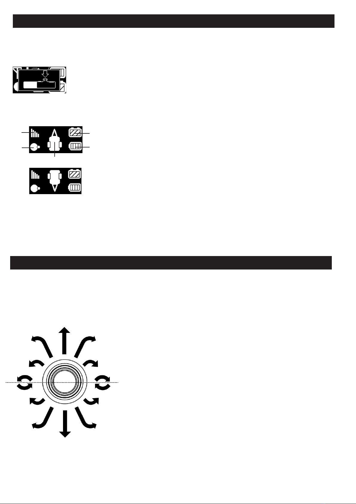
prevent accidental operation of the thumbstick the handset is locked. This is shown by the image below:
Once the thumb stick has been unlocked access to the homescreen will be granted and operation of the mover can begin. Note at
any point during operation the thumb stick can safely be disabled by clicking the thumbstick button (Fig.1B). The mover operation
homes screen is explained below. If any of the icons are ashing this indicates an issue, please refer to troubleshooting.
To manouver your caravan move the thumb stick in the direction you would like to travel. The further the thumb stick is moved
outwards from the centre the faster the mover will operate. To turn the caravan progressively move the thumbstick to the side
from the forward position. At any time the orientation of the caravan controls can be ipped by pressing multi-function button
(Fig.1C).
The Quattro mover utilises a thumb stick for precise control over speed and direction. The speed of operation is dictated by how far
the stick moves from its centre point, to the outer point. Direction is dictated by the radial position of the thumbstick (moving the
stick from left to right).
Operation - Using your Quattro Mover
Page 5
Operation - Manouvering
Thumb stick lock function
When the display shows this icon, the thumb stick operation is disabled. This mode can be exited and
entered by clicking your thumbstick (Fig.1B). Note the thumbstick will only click when it is centred.
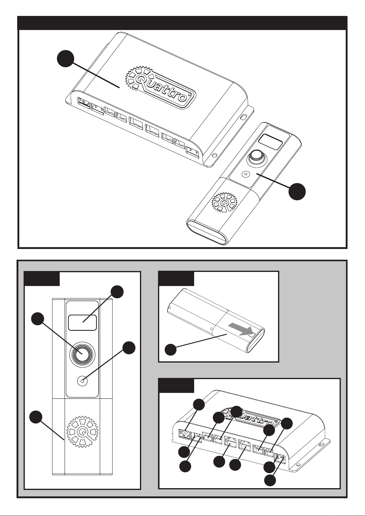
A
B
C
D
E
(A) Signal strength - Indicates signal strength between handset and control unit inside cara-
van.
(B) Mover engagement status - Circles touching indicates movers are engaged onto wheels.
- Circles seperated indicates movers are disengaged.
(C) Leisure battery status - Indicates charge level of leisure battery, for maximum perfor-
mance ensure battery is fully charged and showing 4 bars before operating mover.
(D) Handset battery status - Indicates handset battery level.
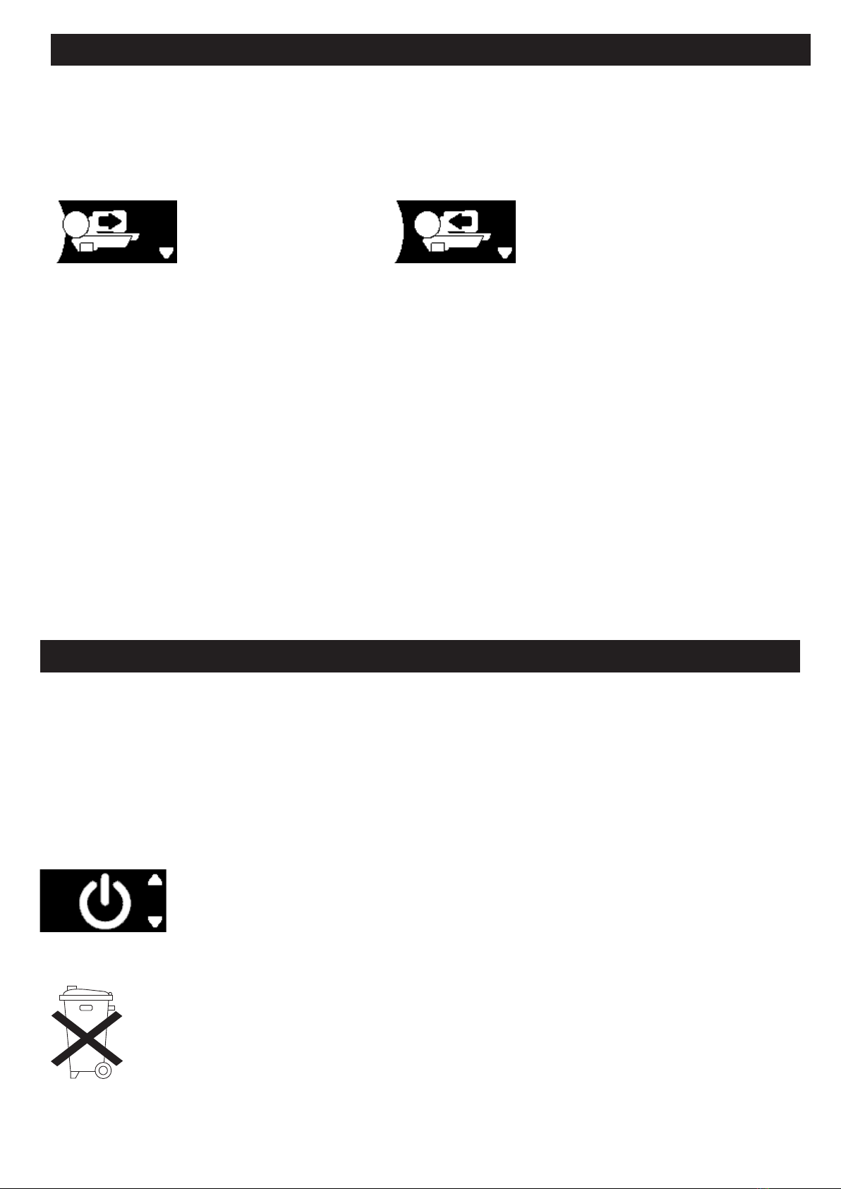
(E) Mover orientation - This shows the direction of travel of the caravan, when the thumb
stick is moved the caravan will follow in this direction. By default the hitch is designated as
the forward direction. At any time press the multi-function button (Fig.1C) to ip the caravan
orientation, the rear of the caravan will then move forward when the thumb stick is moved
upwards.
Caravan orientation ipped
Refer to your handset screen to ensure the caravan is orientated in the desired
way. For example if the hitch is at the top of the display, when the thumb stick
is moved upwards the hitch side of the caravan will move forward. If the rear of
the caravan is at the top of the display, the rear of the caravan will move forward
when the thumb stick is moved upwards.
For uid operation always begin by moving the stick in the general direction you
would like to head (forwards or reverse), the futher the thumb stick moves away
from the centre the faster the mover will operate. From this point progressively
move the stick radially (sidewards) to acheive a uid change in direction. The
more the stick is moved sidewards the tighter the turning radius that will be
acheived. Note moving the thumb stick to the hard right or left position will en-
gage the spin on the spot function on single axle caravans, which may counteract
the direction of travel in some instances.
Single axle caravans have the ability to spin on the spot. To engage this, move
the stick into the hard right or hard left position from centre . The spin function is
biased in favour of the forward direction, so if transitioning from a reverse direc-
tion the spin function may counteract the direction of travel. For the best level of
control operate the spin function from a static position.
The Quattro electronics have an automatic brake feature to prevent caravan run
away on an incline, this can mean when decending with a heavy load the level of
directional control is reduced. For best levels of control decend using the hard
forward and reverse controls, stop periodically and adjust direction with the spin
functions. Full uid directional controls are available for operation on level ground
and on inclines.

Page 6
-
Always ensure your caravan handbrake is on before engaging or disengaging the mover sytem to prevent unwanted movement of
the caravan. Only release the handbrake when the mover is securely engaged to the tyre and you are ready to move the caravan.
Quattro600 (Auto Mover) - From the home screen, hold the multifunctional button (Fig.1C) for 2 seconds to enter the engagement
screen of the menu system as shown below. Move the thumb stick to the left position to begin engagement of the mover system.
Do disengage the mover move the thumbstick to the right position. The display will show you the live status of engagement.
Once engagement is completed, press the multifunctional button (Fig.1C) to return to the home screen and begin operating the
Quattro mover in the desired direction (Pressing up and down on the thumbstick will allow navigation through the other handset
functions including shutdown, settings and diagnostics. To select a menu item click down thumb stick (Fig.1B).)
Quattro500 (Manual Mover) - In order to engage the rollers, t the end socket of the Engagement Tool (6) on the spindle (Fig.2G &
Fig.4A) on the right or left drive unit.
Position the engagement tool parallel to the ground, then rotate the tool through approximately 180 degrees. Note: to engage the
rollers you always rotate the tool towards the tyre, irrespective of which side you are operating the engagement from.
The engagement mechanism utilises a simple over-centre cam that pushes the rollers onto the tyres and then locks into place
automatically. If the mover has been installed correctly, at exactly 20mm away from the tyres when disengaged, the amount of
force provided onto the tyre by the roller will be sucient for most circumstances of use (Fig.6).
To disengage the rollers, simply ret the tool onto one of the spindles and rotate away from the tyre. Please note that you will feel
a small amount of resistance initially as you disengage the cam from its locked position; the spring will then do the rest of the work
and pull the roller away from the tyre and into the fully disengaged position (Fig.5).
Turn o isolation key to cut power to the Quattro control box. To turn o the handset hold the multifunctional button (Fig.1C) for 2
seconds to enter the system menu.
Quattro500 (Manual Mover) - On the manual mover the engagement display is disabled, so by default the shutdown menu item
will be shown imediately. Click thumb stick button (Fig.1B) to shut down the handset. If an engagement menu is shown, ensure
correct mover model is selected in the settings menu (see settings section).
Quattro600 (Auto Mover) - Press multifunctional button (Fig.1C) to enter the engagement screen within the system menu. Move
the thumb stick in the downwards direction to show the shutdown menu item and press the thumb stick button (Fig.1B) to turn o
the handset.
Changing batteries in the remote control:
Open the rear cover of the handset by pushing gently and sliding the rear cover in the direction of the
arrow (Fig.2). Take out the depleted/old batteries and dispose in the appropriate way (check with your
local authority for correct disposal of batteries). Install new replacement batteries. Make sure to use leak
proof batteries (No claims under guarantee can be considered for damage caused by leaking batteries).
Slide the rear cover on gently and it will click into place.
Operation - Mover engagement
Mover currently engaged, move
thumbstick right to disengage.
Mover currently disengaged, move
thumbstick left to engage.
Operation - Shutdown procedure
Note it may take a few moments for
the handset to shut down.

Page 6
AUS:Photographs & diagrams for illustration purposes only. Actual product may dier slightly. All weights & dimensions are approximate. The manufac-
turer reserves the right to change product specication without prior notice. E & OE.
The Quattro handset has a settings menu which allows the user to pair their handset or change operating modes. With the handset
powered on and at the home screen, hold the multi-function button (Fig.1C) for two seconds and then move the thumb stick
downwards to move through the menu items. Once the settings icon (gear icon) is shown press the thumb stick button (Fig.1B) to
enter the menu. Once the settings menu is entered, moving the thumbstick up and down to desired function. At any point, press
multifunctional button (Fig.1C) to go back to previous screen, or hold for two seconds to return to home screen.
Unit fails to operate or moves intermittently:
Handset not connected - Ensure that all home screen items (Fig.1A) are solid and not ashing. If they are then it is likely that the
handset has not yet connected. Move closer to the caravan, if the handset still fails to connect run through the handset pairing
process. Ensure that power is getting to the Quattro control box before beginning the pairing process.
Check the battery of the remote control. If empty, renew using two new ‘AA’ 1.5V batteries.
Caravan battery could be empty. Check that the leisure battery is fully charged. Refer to handset display (Fig.1A)
Caravan battery could be low - with the rollers engaged. Ensure that when operating the mover that the leisure battery icon on
display (Fig.1A) remains at least at 3 bars under load. If the charge indicator is dropping to 2 or below it may indicated a depleted or
damaged battery.
Electronics current limit reached. Allow the mover to sit for 30 seconds, this will allow the electronics to restart and operation will
begin again. If the problem persists call your Quattro mover supplier.
Check the cable-connection between the caravan battery and the control unit.
Badly connected or corroded battery terminals can cause intermittent problems, check battery terminals, clean and connect again.
Low signal - ensure that before operating the mover that the signal between the control box and handset is good. Refer to handset
display (Fig.1A). The mover will operate best with at least 3 bars of signal.
Futher Diagnostics - At the bottom of the system menu there is a diagnostic feature. Press thumb stick button (Fig.1B) to enter this
menu. This will overlay the original home screen with useful information that will allow the user/support technician to identify any
areas potentially at fault. When calling the technical support team please have this menu open and ready.
Rollers slip on wheels:
Check that the distance of the rollers to the tyres is 20mm on both sides. Check for correct tyre pressure by referring to your
caravan mnaufacturer’s handbook. If the pressure is low, the roller would need to be pushed into the tyre further than usual to gain
sucient traction.
In case of any doubt, please call your Quattro Caravan Mover supplier.
Page 7
Settings - Handset pairing and operational mode changes
Handset pairing - On the Quattro handset press the thumb stick button (Fig.1B) on the pairing icon shown. It
will enter a pairing mode illustrated by an image of the handset and control box. Hold the handset onto the
top of the control unit. When pairing is successful the pairing screen will automatically exit. Note your handset
is automatically paired from new, so pairing should only be required if the handset has been replaced.
Axle mode selection - This should only be required if the mover has been transfered onto a new caravan, or
the wrong item was selected on intial mover set up. Navigate down through the settings menu to the axle
mode menu item (as shown). Move the thumb stick right and left to cycle through the axle modes. Refer to
rst use section for the details of each mode. To activate the desired mode press thumb stick button (Fig.1B).
Mover model selection - This should only be required if the mover wrong item was selected on intial mover
set up. Navigate down through the settings menu to the model menu item and move the thumb stick right
and left to cycle through the modes. Refer to rst use section for the details of each mode. To activate the
desired mode press thumb stick button (Fig.1B). The selected mode is shown with a white circle in the centre.
Troubleshooting
Diagnostic settings menu icon.
Diagnostic home screen. To exit back
to normal operation homescreen hold
multifunctional button (Fig.1C) for two
seconds.
This manual suits for next models
1
Table of contents
Other Quattro Caravan manuals