Positive Wire
Negative Wire
FIGURE A IN THE MAIN INSTALLATION MANUAL.
Make sure the 12V supply from the battery and any 230V electricity supply are disconnected.
Find a suitable place for the Electronic Control Unit (1), such as a storage area, under a seat or a bed. Make sure this place is dry and
location, ensure that the unit cannot easily be damaged.
Fix the Electronic Control Unit(s) securely into position with four screws (19). Note: if the provided screws are not of suitable length
between control box ports E (Fig.3).
Caution! Take extra care to avoid any chassis members, gas pipes and electrical wires!
Fig.4 - attach positive wire (red) to terminal marked in red on each mover (Fig.4 - 3 & 1). Attach negative wire (black) to remaining
terminal on each motor (Fig.4 - 4 & 2).
Route the motor-cables in accordance with wiring diagram (Fig.4) (red = positive, black = negative).
Keep all motor cables an equal length, so it is advised that each pair of cables is routed towards the centre line of the
you may need to upgrade to our thicker gauge wiring to maintain maximum performance on steep inclines or curbs.
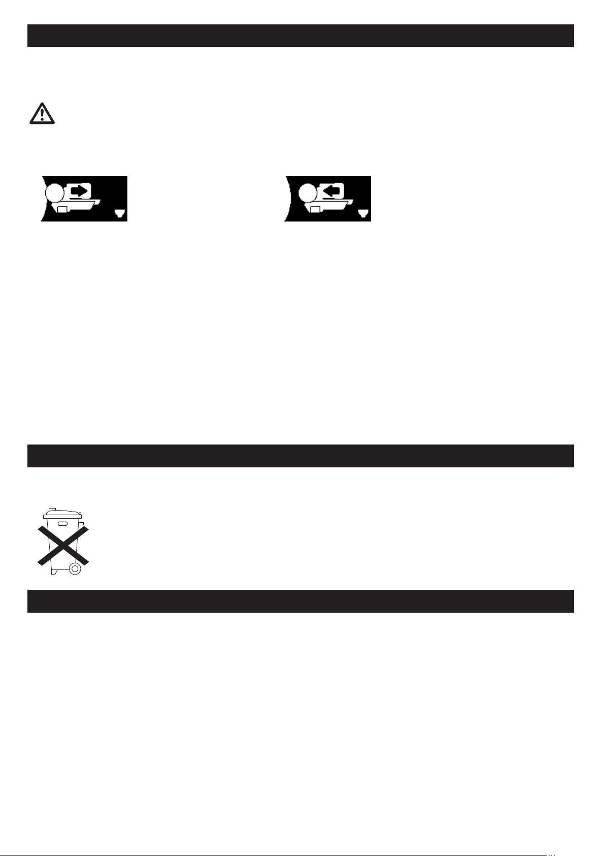
The wiring diagram (Fig.4 + Table.A (see below) depicts the wiring route when installing the motor units in FRONT of the wheels/
axle towards the ‘A’ frame. Please refer to Table.B (below) for installation of the motor units to the REAR of the axle. Note: If you
of this manual to ensure rear axle is correctly wired.
Mark the ends of the Motor Cables (12 & 13) for both motor units using the cable markers (25).The cables for the left and the right
motor should have the same length. Avoid any loops.
electrical cables against sharp edges and dirt) through the drilled hole. Also use a combination of the smaller P-clips (21) where
appropriate.
Secure the Cable Trunking (11) to the chassis or under body of the caravan by using the P-clips (20) and screws (19). Once the motor
cables are through the drilled hole next to the Control Unit (1), cut the cables, ensuring that they are the same length. Remove
approx 5mm of the insulation for the ends. Fix the spade connectors (24) by using crimping pliers. A secure and good quality
connection on each cable is essential.
Attach the connectors to the terminals on the Control Unit (1) (see wiring diagram Fig.20).
Route the Battery Cables (14 & 15) from the battery to the Control Unit (1).
The in-line fuse/s must be installed between the positive battery cable/s that connect the battery and the control
unit. On a AWD system two fuses are required (one per battery wire). For heavier caravans thicker gauge wiring may
also be recommended to ensure maximum performance. Please consult your dealer for further details if necessary.
The Power Isolation Switch (29) will also need to be installed in-line between the Control Unit and the battery, so please plan where
this will be located. If available. This switch must not be installed in the same sealed area as the battery, but may be installed in an
adjacent seperately sealed area, usually there is a space to the side of the battery near the mains power connection.
Installation - Electrical/Electronic Components
Page 3
Motor A Positive (+) cable to terminal M2-
Motor A Negative (-) cable to terminal M2+
Motor B Positive (+) cable to terminal M3-
Motor B Negative (-) cable to terminal M3+
SINGLE AXLE - REAR AXLE FITTING
Motor A Positive (+) cable to terminal M3+
Motor A Negative (-) cable to terminal M3-
Motor B Positive (+) cable to terminal M2+
Motor B Negative (-) cable to terminal M2-
SINGLE AXLE - FRONT AXLE FITTING Table . BTable . A