QM350i
User Manual
User Manual
Q Motion Series
QM350i
5
Speaker cables
Speaker cable needs to be as heavy gauge
as conveniently possible for low-loss results.
Light gauge cable (below 1.5mm) will create
extra resistance and waste amplifier power.
This particularly applies to long speaker
runs. The amplifier’s damping factor statistic
(“punch” for the non technical) is greatly
diminished, so keep your speaker cables
short and as heavy gauge as practical.
Speaker Placement as a Single Box
or in Arrays
The QM350i is intended for use as a single
speaker system or as part of a multiple
speaker setup with or without sub bass
reinforcement. It can also be installed in small
arrays of up to three boxes per array for very
wide coverage applications. When a group
of point source 90 degree speaker boxes
are placed together, it is possible to have
“interference effect” between some of the
boxes causing uneven frequency response.
This can be particularly noticeable in the
mid-high frequency area. If you intend to set
up the QM350i as part of a multiple box array,
see the section ‘Flying the QM350i’.
When positioning the speaker system on a
stage, make sure the HF horn at the top of
the speaker box is above the heads of the
audience. At full power the output of the
QM350i is very high and hearing damage can
result from short to medium term exposure.
When used as a drum-fill monitor on a stage,
the box can sit on the stage however consider
that the HF horn will be at ear level for the
average drummer setup.
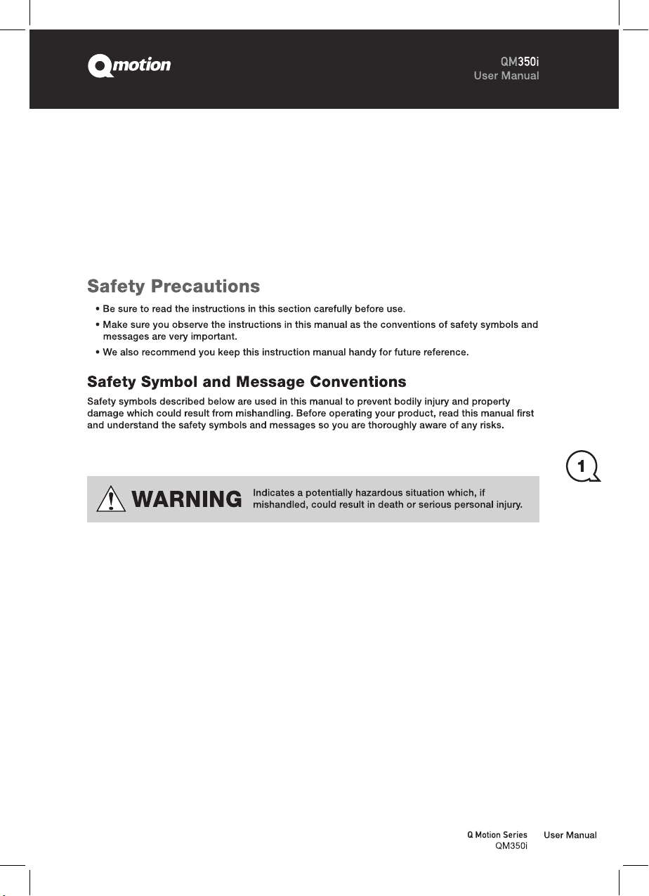
For best results when the QM350i is used as
a front of house speaker, consider angling the
box forward slightly to direct the HF horn to
cover the audience area. The HF horn should
be aimed away from the ceiling and focused
on the intended area of coverage. This will
minimize HF reflections, lower the reverberant
field in the room and give better intelligibility.
Ideal QM350i Flown Configuration