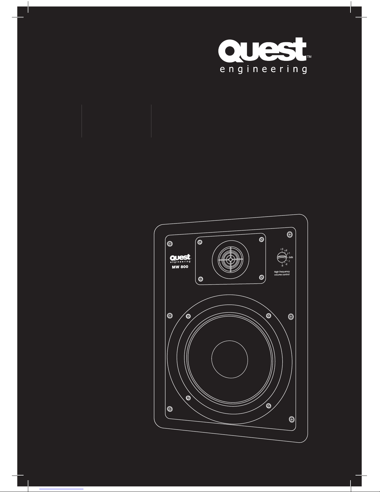
Queat Engineering MW 650 User manual

MW SERIES
MW 650 | MW 800
High-Performance In-Wall Speakers
User Manual

MW 650 | MW 800
User Manual
MW
Series
High-Performance In-Wall Speakers
User Manual
MW 650 | MW 800
User Manual
User Manual
MW
Series
High-Perf
ormance In-Wall Speakers
3
Quest Engineering strongly
advise unless you possess skill
in the proper use of hand and
power tools and have a thorough
understanding of local building
and fi re codes, then the installation
of this speaker should be carried
out by suitably qualifi ed personnel
following locally authorised and
approved safety standards. A
familiarity with the area behind the
wall or ceiling where you plan to
install the speakers is extremely
important. Improper installation
can cause serious injury or
death. If in doubt contact your
Quest Engineering dealer or a
professional installation technician.
Safety Precautions
Do not attempt to clean the
plastic enclosure with solvents or
petrochemical based cleaners.
Installation allowing direct
precipitation is not advised and
installation practise must prevent
liquids from entering the speaker
enclosure.
Do not place sources of heat
on the speaker cabinet such as
lighting equipment or smoke
machines, and where possible
please keep out of direct sunlight.
Attention
Before connecting or operating your new
Quest Engineering speaker, please study the
accompanying instruction manual paying
particular attention to the operating precautions
and wiring procedure.
Quest Engineering will not assume
responsibility for incorrect installation or
operation of this product.
Contents
Safety P.03
Features P.04
Before Installation P.05
Installation P.06
Installation/Wiring P.07
Painting P.10
Specifi cations P.11
CONTENTS
WARNINGS
Register Your Product
Thank you for choosing Quest. Please take
the time to complete your product registration
card which is included with the packaging.
Registering your Quest Engineering product will:
• CONFIRM YOUR WARRANTY
• REGISTER YOUR PRODUCT
• PROTECT YOUR NEW PRODUCT
REGISTER ONLINE:
www.questaudio.net/regist
ration

MW 650 | MW 800
User Manual
MW
Series
High-Performance In-Wall Speakers
User Manual
4
MW 650 | MW 800
User Manual
User Manual
MW
Series
High-Perf
ormance In-Wall Speakers
5
FEATURES
BEFORE INSTALLATION
Description
The Quest Engineering MW Series
High-Performance In-Wall Speakers are the
ideal choice for supplying high-fi delity sound
without the need to use any fl oor or shelf space.
Designed to work right out of the box and into
the wall, the Quest MW Series provide Dynamic
Balance components and aim-able tweeters to
ensure amazing clarity, spacious imaging and
a well-balanced sound in any listening position
The MW series can also be painted to match any
decor blending with your environment to provide
nothing but high-performance sound.
Placement Options
Your Quest Engineering MW Series In-Wall
Speakers can provide you with nearly
endless placement options. Please take in to
consideration your placement options prior to
installation, as an installation requires holes to be
cut in to your walls.
If you are unsure about the correct way to install
or the best way to place your in-wall speakers
please consult a professional audio installation
technician.
You can fi ll a room with sound by installing
in-wall speakers in nearly any wall or ceiling
location. Quest MW Series In-Wall Loudspeakers
have a wide dispersion pattern, allowing you to
focus their sound accordingly.
Adjusting the Tweeter
You can improve the imaging and detail your
Quest MW Series In-Wall Speakers provide by
aiming the tweeter toward your listening position.
When using the MW Series as front/main home
theatre speakers, aim the tweeter toward your
chosen listening position.
For rear/surround speakers installed in walls
or ceilings, aim the tweeter toward the nearest
refl ecting wall, such as an adjacent wall or
ceiling, for a more diffused sound fi eld. If you
prefer a more direct sound, simply aim the
tweeters toward your listening position.
To adjust the tweeters, do so by holding the
edges of the tweeter carefully between the
thumbs and forefi ngers of both hands, then rock
the tweeter slightly to aim it toward the desired
location.
Note:
Quest MW Series In-Wall Speakers are
not
magnetically shielded and should not be
placed closer than 30 cm from a television or
video monitor. If you experience discolouration or
distortion on your display, immediately move the
speakers away from your television or monitor.
A Word on Safety
When you install your Quest MW Series In-
Wall Loudspeakers, make sure you are aware
of the weight of your particular model (see
specifi cations page 11 for the weight of your
particular model) and the sturdiness of the
material into which you are installing the speaker.
Also be aware of any concealed studs, electrical
wiring or plumbing in the wall into which you are
installing the speakers. If unsure of a safe way
to install these speakers, consult a professional
installer, your authorised Quest Engineering
Dealer, or a building contractor.
If you plan to install your MW Series speakers
where they may be in direct contact with water,
it is advisable to use a silicone sealant or caulk
between the frame of the speaker and the wall
surface. This seal should prevent water from
getting behind the loudspeaker and possibly
damaging the wall surface. Do not position the
speaker where water can pool on the surface
of the woofer cone or tweeter dome, as this will
greatly decrease the speaker’s useful life.
Getting the Best Results
Preparation is the key to a tidy and successful
installation and performance. For best bass
response the speaker baffl e should be as close
as possible to an airtight seal, so no vibrating
air from the back of the box can leak through
to the front. “Whistles” and poor bass response
will be the result of poor installation. Time spent
carefully measuring and cutting wall and ceiling
surfaces will save patch up time later. Also
clearly establish that there is suffi cient depth in
wall and ceiling cavities to accommodate the
speaker. With correct installation and wiring
to rigid and airtight surfaces, your MW series
speaker will deliver sonic results normally
associated with top-end hi-fi delity transducers.
Another important point is to make sure you have
enough amplifi er power for the job intended.
A 100 watt speaker driven by a distorting 20
watt amplifi er will not realise the speaker’s full
potential. A low powered amplifi er delivering
signal through long distances of very thin wire
will not give the best results. For long speaker
cable runs, 1.5 – 2.5 mm cable is better.
Matching amplifi er power to the speaker load will
also deliver clarity at higher dB levels and is safer
for the speakers.
What You Will Need
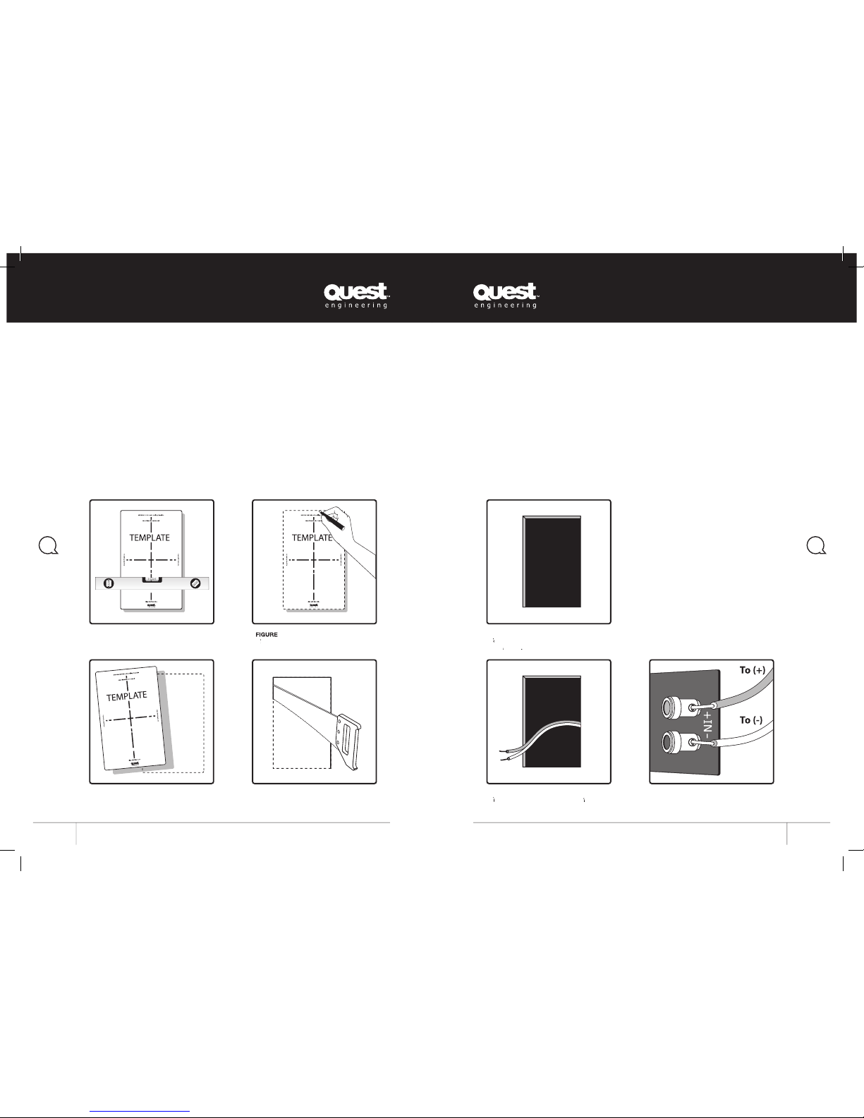
• Pencil for marking the location of installation
• Keyhole saw, utility knife or material-
appropriate incising implement for cutting dry
wall or other wall material
• Spirit Level
• Screwdriver, preferably powered, with
Phillips-Head bit
• Power drill with appropriate bit – optional, for
starting wall cut.
Steps to Installation Success
• Ensure the material into which you intend
to mount the speakers – plaster, dry wall,
panelling, stone, etc. – can support the weight
of the speakers (refer to specifi cation page for
the weight of your product).
• This is an important point! Make sure the
locations you select do not conceal studs,
electrical wiring or plumbing. Prior to
installation, hold the speaker in your chosen
location to make sure it clears obstacles such
as studs, corners, beams, lighting fi xtures and
door/window frames. Your cutout must be at
least 25 mm from adjoining walls or ceiling,
internal studs or plumbing.

MW 650 | MW 800
User Manual
MW
Series
High-Performance In-Wall Speakers
User Manual
6
MW 650 | MW 800
User Manual
User Manual
MW
Series
High-Perf
ormance In-Wall Speakers
7
Installation
• Using the template provided, trace the
installation location with a pencil. You can do
this by holding the template in your preferred
location and tracing around it. Use a spirit
level to ensure the template is straight and
plumb. This is the exact cutout size
[
fi gures 1-3
].
• Once you have cut the hole, fi sh your
previously positioned wiring out of the hole
and connect the speaker [
fi gure 6
]. Follow
the hook-up directions included with your
receiver.
INSTALLATION
INSTALLATION/WIRING
FIGURE
6
F
ish your previo
Fish your previoF
usly positioned wir
ing out
usly positioned wiring out usly positioned wir
of the hole ready to connect the speaker.
FIGURE 1
Use the template provided along with a
Level to set out the cut out hole
.
FIGURE
2
M
ark out the template using a permanent
Mark out the template using a permanent M
marker.
FIGURE
3
Remove
template to show cutting guides
.
FIGURE
7
Ensure connection to the correct terminals.
Connect by pushing down on the terminal.
• Carefully cut the hole with the appropriate
cutting tool for your wall material. Start the
hole by drilling a hole inside of your tracing
(with the drill-bit touching the line). Use this
hole to insert the saw or knife and begin
cutting [
fi gure 4
].
FIGURE
5
Y
ou should now have
You should now have Y
the space to insert
the
s
peaker
speakers
.
peaker.peaker
FIGURE
4
Using
an appropriate tool, cut out the
marked area.
Strip 12 mm of insulation from each of the
two conductors of the wire to expose the bare
metal and twist each of the conductors into a
single un-frayed strand (so you have two un-
frayed strands). Note that one of the terminals
on the rear of each speaker is red (+) and the
other is black (-).
Ensure you connect the wire from the red
terminal (+) of your amplifi er, or receiver, to
the red terminal (+) on your speaker and make
sure the black terminal (-) of your amplifi er,
or receiver, to the black terminal (-) on your
speaker [
fi gure 7
]. Most wire has some
indicator (such as colour-coding, ribbing or
writing) on one of the two conductors to help
you maintain consistency.

MW 650 | MW 800
User Manual
MW
Series
High-Performance In-Wall Speakers
User Manual
8
MW 650 | MW 800
User Manual
User Manual
MW
Series
High-Perf
ormance In-Wall Speakers
9
INSTALLATION
INSTALLATION
• To install the speaker, fi rst carefully remove
the grille using a straightened paper clip or
other pointed metal tool. Insert the point into
one of the grille perforations near a corner
and lift the grille free. Never use a knife or
screwdriver to pry between the grille and the
speaker frame. Doing so will cause damage
to your speaker.
• Loosen the rotating wall clamps by
unscrewing them. Make sure the rotating
wall clamps are fl ipped inwards, so that
your speaker fi ts into your cutout without
nicking your wall [
fi gures 8-9
]. Then place
the speaker carefully into the cutout. It is a
good idea to use your level to help correctly
align the speaker [
fi gure 10
]. Tighten the wall
clamp screws with a screwdriver. This will
rotate the wall clamps and secure the speaker
to the wall [
fi gure 11
]. Please note, tightening
the centre screws before tightening the
corners will give you the most fl ush fi t to your
wall.
Warning
:
Do not over-tighten the wall
clamp screws
.
FIGURE
8
Ensure all locating lugs are straight before
inserting the speaker into the wall
MW 800
high frequency
volume control
+3 +2
+1
0db
-1
-2
-3
FIGURE
10
Once you have put the speaker in the wall
align again using a Level
.
align again using a Level.align again using a Level
• Carefully reinstall the grille by fi tting it into
its recess so that it is just resting on the
frame. Starting with one corner, go around
the speaker and push the grille into the grille
notch a little bit at a time. Be gentle as the
grille may easily bend out of shape with
rough handling. You will feel a positive “snap”
when it is fully in place. Congratulations,
you have successfully installed your Quest
Hi-Performance In-Wall Speakers. Enjoy!
MW 800
high frequency
volume control
+3 +2
+1
0db
-1
-2
-3
FIGURE
11
Carefu
lly
tighten all fastening screws. D
o
not over-tighten these screws.
FIGURE
9
Incorrect Operation depi
c
ted above.

MW 650 | MW 800
User Manual
MW
Series
High-Performance In-Wall Speakers
User Manual
10
MW 650 | MW 800
User Manual
User Manual
MW
Series
High-Perf
ormance In-Wall Speakers
11
PAINTING
SPECIFICATIONS
Quest Engineering MW Series In-Wall Speaker Specifi cations
MW 650 Specifi cations
Size
307
mm
(L) x 209.5
mm
(W) x 91.5
mm
(D)
Nominal Power
60 W
Max Power
120 W
DCR
W
oofer: 6.5
Woofer: 6.5 W
Ω, Dome Tweeter: 5.4
Ω
Mounting Diameter
271.5 mm (L) x 185 mm (W) x 80 mm (D)
Weight
1.85 Kg
Characteristics
Impedance
8
Ω
±
1.2
Ω
Resonant Frequency Range
60 Hz
± 20%
Frequency Response
Fo~20 KHz
± 4 KHz
SPL
86 dB
± 2 dB
Polarity
Cone paper must be moved forward when connecting the terminal marked
(+) or red with A positive instantaneous voltage
Crossover Cut Off Frequency
3000 Hz
Insulation
More than 1 M
Ω
between terminal & a bare metal section of speaker
MW 800 Specifi cations
Size
358 mm (L) x 255 mm (W) x 99.5 mm (D)
Nominal Power
80 W
Max Power
160 W
DCR
W
oofer: 7.2
Woofer: 7.2 W
Ω, Dome Tweeter: 5.4
Ω
Mounting Diameter
323 mm (L) x 220 mm (W) x 88 mm (D)
Weight
2.65 Kg
Characteristics
Impedance
8
Ω
±
1.2
Ω
Resonant Frequency Range
55
Hz
± 20%
Frequency Response
Fo~20 KHz
± 4 KHz
SPL
87
dB
± 2 dB
Polarity
Cone paper must be moved forward when connecting the terminal marked
(+) or red with A positive instantaneous voltage
Crossover Cut Off Frequency
3000 Hz
Insulation
More than 1 M
Ω
between terminal & a bare metal section of speaker
All specifi cations are correct at time of printing, Quest Engineering reserves the right to change
specifi cations at any time and won’t be held responsible for any typographic errors in this publication.
Painting Your In-Wall Speakers
Here’s what you will need:
• Paint of your choice – for an easier way to
complete the job, we strongly advise spray
painting the grille
• A paper clip, corkscrew or other tool with a
pointed tip, to be used for removing the paint-
able grille.
• Masking tape
• Paint Mask; to cover the un-paint-able areas
– this is supplied.
Preparing to Paint
1. Separate the parts of the speaker. If the
speaker is not yet installed, the grille can be
removed simply by pushing the clamp screws
forward, to push the grille off the speaker
from the inside. If the speaker is already in
the wall, carefully hook the grille with a bent
paper clip and pull it gently away from the
frame.
2. When painting the frame of the speaker, use
the supplied painting masks to carefully mask
off the front of the speakers to protect the
drivers and baffl es while painting. You can do
this while the speaker is already installed in
the wall – e.g. if you are repainting the room.
If you do not have the paint mask, carefully
mask the speaker components using paper
and masking tape.
Painting the Frame
1. Apply paint to the exposed (unmasked) parts,
using two or more thin coats. Spray painting
is recommended for the best fi nish.
2. When the paint is completely dry, remove the
masking material.
Painting the Grille
1. The grille of the MW Series speaker features
an even, protective powder coating, making it
an ideal paint primer.
2. Grilles must be spray painted. Do not use a
brush and paint. Thick, brushed paint is highly
likely to clog the grille holes.
3. Before spray painting the grille, carefully
remove the grille’s fabric scrim by peeling it
away from the inside of the grille. Place this
on a clean, fl at surface where it will not get
wrinkled.
4. After removing the grille by carefully hooking
it with a bent paper clip (or cork screw) and
pulling it gently away from the frame, spray on
two thin coats of fi nish colour. If you are using
a compressor and spray gun, use the fi nest,
most diffuse setting. Be careful not to fi ll the
holes in the grille with paint.
5. When the grille is dry, carefully press the
fabric scrim back into place, on the inside
of the grille. The special fabric scrim hides
the speaker’s drivers from view, and will not
interfere with the sound.
6. Carefully reinstall the grille by fi tting it into
its recess, so that it is just resting on the
frame. Starting with one corner, go around
the speaker and push the grille into the grille
notch, a little bit at a time. Please be gentle,
as the grille may easily be bent out of shape
by rough handling. You will hear a positive
“snap” when it is fully in place.

www.questaudio.net
Table of contents
Other Queat Engineering Speakers manuals