Queclink GL300W User manual

GL300W External Battery Kit User
Manual
GSM/GPRS/WCDMA/GNSS Tracker
GL300WEBKUM001
Revision: 1.00

GL300W External Battery Kit User Manual
GL300WEBKUM001 -1-
Document Title GL300W External Battery Kit User Manual
Version 1.00
Date 2015-10-09
Status Release
Document Control ID GL300WEBKUM001
General Notes
Queclink offers this information as a service to its customers, to support application and
engineering efforts that use the products designed by Queclink. The information provided is
based upon requirements specifically provided to Queclink by the customers. Queclink has
not undertaken any independent search for additional relevant information, including any
information that may be in the customer’s possession. Furthermore, system validation of
this product designed by Queclink within a larger electronic system remains the
responsibility of the customer or the customer’s system integrator. All specifications
supplied herein are subject to change.
Copyright
This document contains proprietary technical information which is the property of Queclink
Limited. The copying of this document, distribution to others, and communication of the
contents thereof, are forbidden without express authority. Offenders are liable to the
payment of damages. All rights are reserved in the event of a patent grant or registration of
a utility model or design. All specification supplied herein are subject to change without
notice at any time.
Copyright © Queclink Wireless Solutions Co., Ltd. 2010
Queclink
Confidential

GL300W External Battery Kit User Manual
GL300WEBKUM001 -2-
Contents
Contents ............................................................................................................................................2
Table Index ........................................................................................................................................3
Figure Index.......................................................................................................................................4
0. Revision history .............................................................................................................................5
1. Introduction ..................................................................................................................................6
1.1. Reference.............................................................................................................................6
1.2. Terms and abbreviations .....................................................................................................6
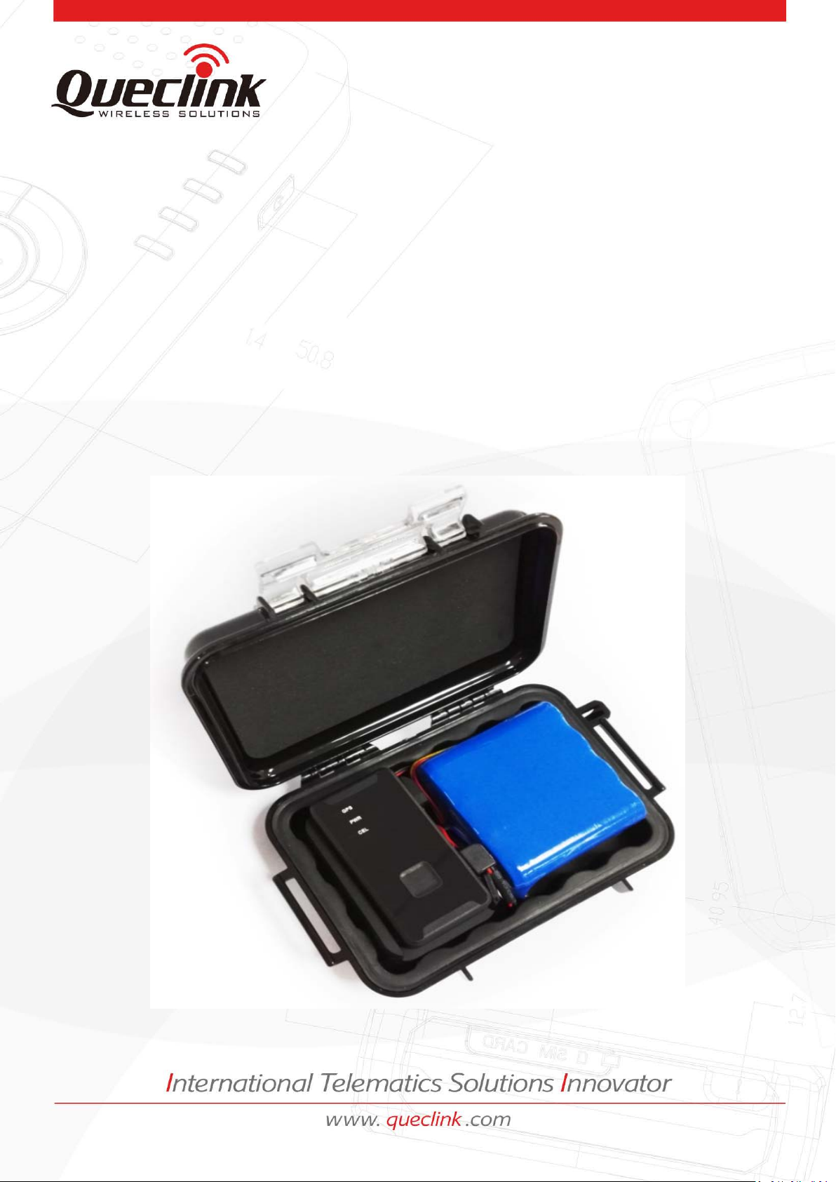
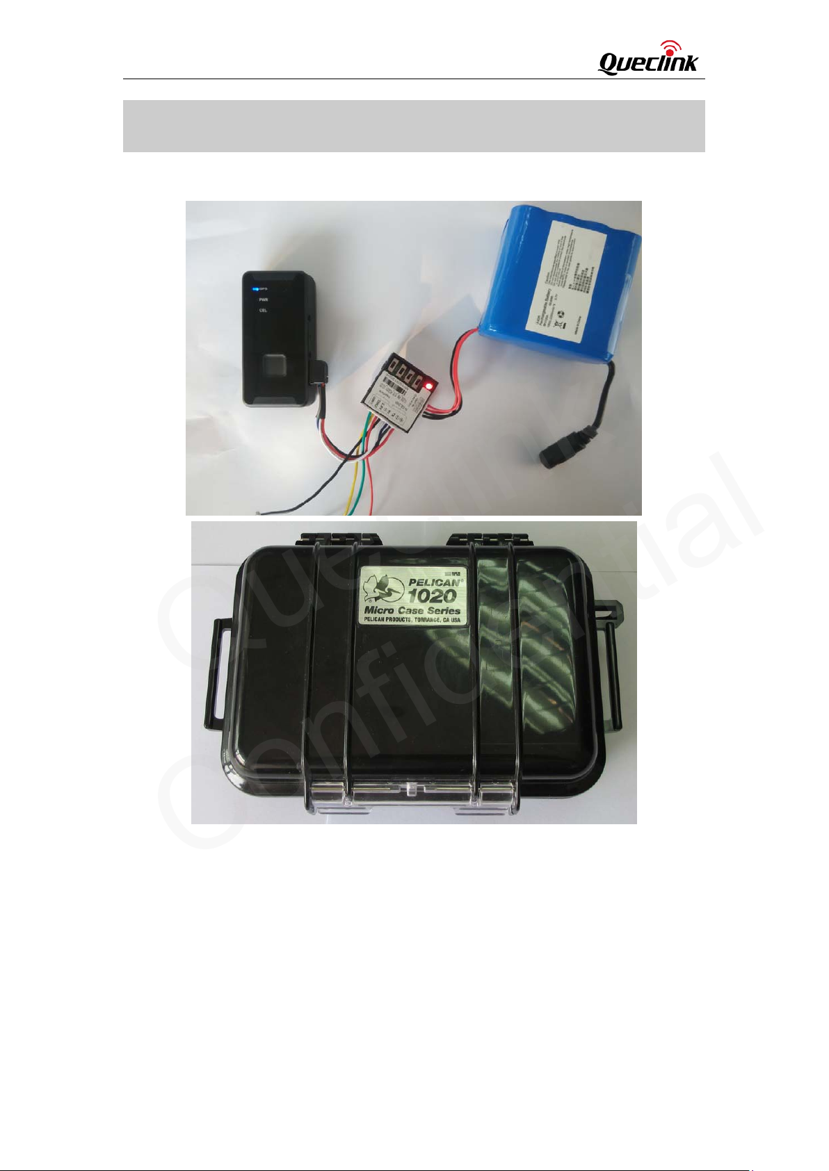
2. Product Overview..........................................................................................................................7
2.1. Appearance .........................................................................................................................7
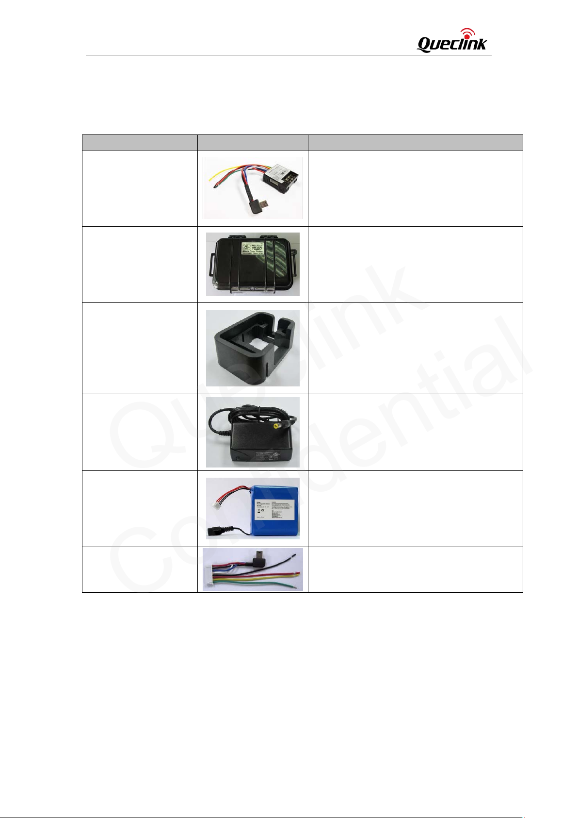
2.2. Parts List ..............................................................................................................................8
3. PCU (Power Control Unit)..............................................................................................................9
3.1. Overview..............................................................................................................................9
3.2. Interfaces...........................................................................................................................10
3.2.1. VBAT IN Interface.............................................................................................10
3.2.2. Digital Input Interface......................................................................................11
3.2.3. PWR Output Interface .....................................................................................14
3.3. Toggle Switch.....................................................................................................................14
3.3.1. SW101 .............................................................................................................15
3.3.2. SW102 .............................................................................................................15
3.3.3. SW103 .............................................................................................................15
3.3.4. SW104 .............................................................................................................15
3.4. Indication LED....................................................................................................................16
3.5. Onboard Motion Sensor
....................................................................................................16
3.6. Relations between Logical Status and Power Output .......................................................16
4. External Battery...........................................................................................................................17
4.1. Battery Specification .........................................................................................................17
4.2. How to Charge the Battery................................................................................................17
5. Pelican 1020 BOX.........................................................................................................................18
6. System Connection With GL300W ..............................................................................................19
6.1. Connection Overview ........................................................................................................19
6.2. Air Protocol Interface Relate to PCU .................................................................................20
6.2.1. GTLSW .............................................................................................................20
6.2.2. GTTSW.............................................................................................................21
6.2.3. GTOMS ............................................................................................................21
6.2.4. GTRST ..............................................................................................................22
7. Configuration Q&A ......................................................................................................................24
Queclink
Confidential

GL300W External Battery Kit User Manual
GL300WEBKUM001 -3-
Table Index
TABLE 1: REFERENCE.................................................................................................................................6
TABLE 2: TERMS AND ABBREVIATIONS .....................................................................................................6
TABLE 3: PART LIST....................................................................................................................................8
TABLE 4: VBAT IN INTERFACE REFERENCE...............................................................................................10
TABLE 5: DIGITAL INPUT INTERFACE REFERENCE....................................................................................11
TABLE 6: PWR OUTPUT INTERFACE REFERENCE .....................................................................................14
TABLE 7: LOGICAL STATUS R EL ATIO NS ....................................................................................................16
TABLE 8: BATTERY SPECIFICATION ..........................................................................................................17
TABLE 9: +RESP:GTLSW MESSAGE FORMAT............................................................................................20
TABLE 10: +RESP:GTTSW MESSAGE FORMAT .........................................................................................21
TABLE 11: +RESP:GTOMS MESSAGE FORMAT.........................................................................................22
TABLE 12: +RESP:GTRST MESSAGE FORMAT...........................................................................................22
Queclink
Confidential

GL300W External Battery Kit User Manual
GL300WEBKUM001 -4-
Figure Index
FIGURE 1: APPEARANCE OF GL300W EBK ................................................................................................7
FIGURE 2: PCU INTERFACE ........................................................................................................................9
FIGURE 3: VBAT IN INTERFACE ................................................................................................................10
FIGURE 4: DIGITAL INPUT INTERFACE .....................................................................................................11
FIGURE 5: DIGITAL INPUT 1 CONNECT TO REED SWITCH .......................................................................12
FIGURE 6: DIGITAL INPUT 1 CONNECT TO TOGGLE SWITCH ...................................................................12
FIGURE 7: DIGITAL INPUT 2 CONNECT TO REED SWITCH .......................................................................13
FIGURE 8: DIGITAL INPUT 2 CONNECT TO TACT SWITCH ........................................................................13
FIGURE 9: PWR OUTPUT INTERFACE ......................................................................................................14
FIGURE 10: TOGGLE SWITCHES...............................................................................................................15
FIGURE 11: HOW TO CHARGE THE EXTERNAL BATTERY .........................................................................17
FIGURE 12: PELICAN 1020 BOX APPEARANCE ........................................................................................18
FIGURE 13: CONNECTION OVERVIEW.....................................................................................................19
Queclink
Confidential

GL300W External Battery Kit User Manual
GL300WEBKUM001 -5-
0. Revision history
Revision Date Author Description of change
1.00 2010-12-10 Evan.Tu Initial
Queclink
Confidential

GL300W External Battery Kit User Manual
GL300WEBKUM001 -6-
1. Introduction
GL300W External Battery Kit is a set of accessories include an external battery, a power control
unit and a pelican waterproof casing. It will greatly improve the working time of GL300W and
also let the GL300W can be used for some special application like container tracking.
1.1. Reference
Table 1: Reference
SN Document name Remark
[1] GL300W @Tracker Air Interface Protocol.pdf
1.2. Terms and abbreviations
Table 2: Terms and abbreviations
Abbreviation Description
NO Normally Open
NC Normally Close
EBK External Battery Kit
PCU Power Control Unit
Queclink
Confidential

GL300W External Battery Kit User Manual
GL300WEBKUM001 -7-
2. Product Overview
2.1. Appearance
Figure 1: Appearance of GL300W EBK
Queclink
Confidential

GL300W External Battery Kit User Manual
GL300WEBKUM001 -8-
2.2. Parts List
Table 3: Part List
Name Picture Description
PCU
PCU manages the power from the external
battery
. It has build in motion sensor and
external digital inputs.
Pelican 1020 Waterproof
Box
All the components except the AC-DC charger
will be put into the Pelican 1020 Waterproof Box.
Frame for GL300W and
PCU
The frame is used to fix the PCU and GL300W.
AC-
DC Charger for
External Battery
AC-DC Charger is used to charger the external
battery. Please notice that the PCU must be
removed from the external battery when
charging.
External Battery
High capability battery, 17600 mAh.
Connect Cable
This cable is used to connect GL300W to PCU and
connect external switch to PCU.
Queclink
Confidential

GL300W External Battery Kit User Manual
GL300WEBKUM001 -9-
3. PCU (Power Control Unit)
3.1. Overview
There are two connectors on the GL300W EBK: One is 4-pin connector for VBAT IN interface; the
other is 8-pin connector for Digital Input and PWR Output interface.
The PCU has an onboard motion sensor which can detect the motion/rest status of the PCU.
Figure 2: PCU Interface
Queclink
Confidential

GL300W External Battery Kit User Manual
GL300WEBKUM001 -10-
3.2. Interfaces
3.2.1. VBAT IN Interface
The external battery should be connected to 4-pin connector which used as VABT IN interface of
PCU. The pin description is shown in Table 4.
Figure 3: VBAT IN Interface
Table 4: VBAT IN Interface Reference
Pin Number Description
1 GND
2 GND
3 Power(3.4V~4.2V)
4 Power(3.4V~4.2V)
1 2 3 4
Queclink
Confidential

GL300W External Battery Kit User Manual
GL300WEBKUM001 -11-
3.2.2. Digital Input Interface
Digital Input interface includes 2 digital inputs which can be used to monitor the external digital
signal. They can be connected to toggle switch, tact switch or reed switch. There are four pins on
the left side of the 8-pin connector. The pin description is shown in Table 5.
Figure 4: Digital Input Interface
Table 5: Digital Input Interface Reference
Pin Number Description
1 Digital input 1
2 Digital input 2
3 2.8V output
4 GND
3.2.2.1. Digital Input 1
Digital input 1 work as a lock switch and it is recommended to connect to a toggle switch or a
reed switch.
If SW103 is set to ‘H’, the logical status is ‘0’ when the electrical level of digital input 1 is high. It
will be ‘1’ if the electrical level of digital input 1 is low.
If SW103 is set to ‘L’, the logical status is ‘1’ when the electrical level of digital input 1 is high. It
will be ‘0’ if the electrical level of digital input 1 is low.
1 2 3 4
Queclink
Confidential

GL300W External Battery Kit User Manual
GL300WEBKUM001 -12-
The logical status of digital input 1 will effect on the power output of PCU. Please refer to chapter
3.6 for detail.
The reference connection of digital input 1 is shown in following figure.
Figure 5: Digital Input 1 Connect to Reed Switch
Figure 6: Digital Input 1 Connect to Toggle Switch
3.2.2.2. Digital Input 2
Digital input 2 works as a trigger switch and it is recommended to connect it to a tact switch or a
reed switch.
Queclink
Confidential

GL300W External Battery Kit User Manual
GL300WEBKUM001 -13-
The default logical status of digital input 2 is ‘0’ and it will be reversed when the electrical level of
digital input 2 changes two times.
The logical status of digital input 2 will effect on the power output of PCU. Please refer to chapter
3.6 for detail.
The reference connection of digital input 2 is shown in following figure.
Figure 7: Digital Input 2 Connect to Reed Switch
Figure 8: Digital Input 2 Connect to Tact Switch
Queclink
Confidential

GL300W External Battery Kit User Manual
GL300WEBKUM001 -14-
3.2.3. PWR Output Interface
The power output is included in the PWR Output interface. It also includes the UART interface for
the communication between GL300W and PCU. There are four pins on the right side of the 8-pin
connector. The pin description is shown in Table 6.
Figure 9: PWR Output Interface
Table 6: PWR Output Interface Reference
Pin Number Description
5 RXD
6 TXD
7 GND
8 Power output(3.4V~4.2V)
3.3. Toggle Switch
The PCU has four toggle switches: SW101 to SW104. They are used for the configuration of the
PCU.
5 6 7 8
Queclink
Confidential

GL300W External Battery Kit User Manual
GL300WEBKUM001 -15-
Figure 10: Toggle Switches
3.3.1. SW101
SW101 is used to enable/disable the onboard motion sensor.
3.3.2. SW102
SW102 is used to configure the auto power up function. If it is set to ‘L’, the power output will be
enabled for at least 5 minutes every day even when the PCU is in rest. If SW102 is set to ‘H’, the
power output will never be enabled when the PCU is in rest. (In case the logical status of two
digital inputs are all 0).
There are some reporting messages relate to this function. Please refer to chapter 6.2.4 for
details.
3.3.3. SW103
SW103 is used to configure the logical status of digital input 1.
3.3.4. SW104
SW104 is used to enable/disable the indication LED. If SW104 is set to ‘H’, the LED will be
disabled. If SW104 is set to ‘L’, the LED will be enabled.
Please notice that even when the LED is enabled, it will only light when the power output is
enabled.
Queclink
Confidential

GL300W External Battery Kit User Manual
GL300WEBKUM001 -16-
3.4. Indication LED
The Red LED is used to indicate the output of the power. It is controlled by the toggle switch
SW104 and the power output.
3.5. Onboard Motion Sensor
If SW101 is set to ‘H’, the motion sensor will be disabled and the logical status of motion sensor
will always be ‘0’. If SW101 is set to ‘L’ then the motion sensor will be enabled. The logical status
of motion sensor will be ‘1’ when the PCU is in motion, and be ‘0’ when the PCU is in rest. Please
notice that there will be five minutes’ delay after the logical status of motion sensor change from
‘1’ to ‘0’.
The logical status of motion sensor will effect on the power output. Please refer to chapter 3.6
for detail.
3.6. Relations between Logical Status and Power Output
Only when the logical status of digital input 1 and 2 are all 0, the power output can be disabled.
PCU will send the report on every logical status change to the backend server via GL300W. Please
refer to chapter 6.2 for detail.
The description of the logical status is shown in following table. The power output will be
disabled when the logical status of power output changes from 1 to 0. But please notice that
there will be five minutes delay to let the GL300W send out the report message to backend.
Table 7: Logical Status Relations
Logical status of
digital input 1
Logical status of
digital input 2
Logical status of
motion sensor
Logical status of
Power output
0
0 0 0
1 1
1 0 1
1 1
1
0 0 1
1 1
1 0 1
1 1
Queclink
Confidential

GL300W External Battery Kit User Manual
GL300WEBKUM001 -17-
4. External Battery
4.1. Battery Specification
The GL300W EBK includes a large capacity battery which can provide long standby time. The size
of the battery is about 38mm * 80mm * 71mm. There are two connectors on the battery, one is
for power output, and another is used for charging.
The specification of the external battery is listed in following.
Table 8: Battery Specification
Item Specification
Rated Capacity min 17.6Ah
Normal Voltage 3.7V
Charge Ending Voltage 4.2 ± 0.05V
Charge current Standard charge:0.2CmA
Rapid charge:1500mA
Discharge Ending Voltage 2.75V
Max Discharging Current 2A
Impedance ≦130mΩ
4.2. How to Charge the Battery
Plug the AC-DC power adapter provided by Queclink into the DC connector of the external
battery.
The indication LED on the adapter will be red during charging and changes to green when
the battery is fully charged.
Charging time is about 16 hours.
Figure 11: How to Charge the External Battery
Queclink
Confidential

GL300W External Battery Kit User Manual
GL300WEBKUM001 -18-
5. Pelican 1020 BOX
The GL300W EBK is included in a Pelican 1020 waterproof casing. It is designed following the
IP67 standard which can provide protection for internal components. The dimension of this box
is 16cm * 12cm * 6cm.
Figure 12: Pelican 1020 Box Appearance
Queclink
Confidential

GL300W External Battery Kit User Manual
GL300WEBKUM001 -19-
6. System Connection With GL300W
6.1. Connection Overview
The connection between external battery, PCU and GL300W is shown in following figure.
Figure 13: Connection Overview
Queclink
Confidential
Other manuals for GL300W
3
This manual suits for next models
1
Table of contents