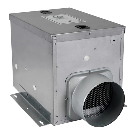
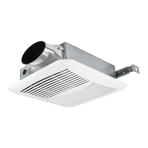
QuFresh QuF100X User manual

TO REDUCE THE RISK OF FIRE, ELECTRIC SHOCK, OR INJURY TO PERSONS,
OBSERVE
THE FOLLOWING:
1. Use this unit only in the manner intended by the manufacturer. If you have questions, contact
the manufacturer at the address or telephone number listed in the warranty.
2. Before servicing or cleaning unit, switch power off at service panel and lock the service
disconnecting means to prevent power from being switched on accidentally. When the service
disconnecting means cannot be locked, securely fasten a prominent warning device, such as a
tag, to the service panel.
3. Installation work and electrical wiring must be done by a qualified person(s) in accordance
with all applicable codes and standards, including fire-rated construction codes and standards.
4. Sufficient air is needed for proper combustion and exhausting of gases through the flue
(chimney) of fuel burning equipment to prevent back drafting. Follow the heating equipment
manufacturer’s guideline and safety standards such as those published by the National Fire
Protection Association (NFPA), and the American Society for Heating, Refrigeration and Air
Conditioning Engineers (ASHRAE), and the local code authorities.
5. When cutting or drilling into wall or ceiling, do not damage electrical wiring and other hidden
utilities.
6. To Reduce The Risk Of Fire Or Electric Shock, Do Not Use This Fan With Any Solid-State
Speed Control Device.
7. This unit must be grounded.
8. Not for Use in Kitchens.
1. For general ventilating use only. Do not use to exhaust hazardous or explosive materials and
vapors.
2. To avoid motor bearing damage and noisy and/or unbalanced impellers, keep drywall spray,
construction dust, etc. off power unit.
3. For residential installations only.
4. Read all instructions before installing or using fan.
5. The motor is permanently lubricated and never needs oiling. If the motor bearings are making
excessive or unusual noises, replace the blower assembly.
MODEL
OFF
READ AND SAVE THESE INSTRUCTIONS
Installer: Leave this manual with the homeowner

ASSEMBLY INSTRUCTIONS
Preparing the Fan
1. Unpack and remove fan carefully from the carton. Confirm that all pieces are present.
2. Choose the location for your fan so that:
a. The intake vent from the outside is placed a minimum of six feet from any other exhaust vent;
b. To ensure the best performance, it is recommended that the length of ducting and the number of
elbows be kept to a minimum, the radius of each elbow be as large as possible for the
installation, and that insulated hard ducting be used.
c. The door can be opened to allow cleaning the filters.
NOTE: The fan must be installed in a location that can be easily accessed once installed.
3. No additional vibration deadening materials are needed for this fan.
Mounting the Fan:
1. Fix the inlet and outlet duct adapter on fan body (Fig.1), insert the tabs on the duct adapter into the
receptacles on the fan body and secure with 1 screw C (ST4*15). Plug in the damper motor into the
receptacle on the housing.
2. Fix the hangers (4 pcs) onto the fan body by 2 screws A(M5*12) each (Fig.2) Note housing is shown
upside down for clarity
3. Confirm the fan is appropriately positioned so the air flow is in the correct direction (the damper is on
the outlet of the fan) and the fan can be easily accessed for cleaning and maintenance.
4. The fan can be mounted directly to studs/joist/blocking using appropriate lag screws (not included) or
suspended from hangar rods (not included). Use thread locker on threads as appropriate.
DUCTING
NOTE: The ducting from this fan to the outside of the building has a strong effect on the air flow, noise
and energy use of the fan. Use the shortest, straightest duct routing possible for best performance, and
avoid installing the fan with smaller ducts than recommended. Insulation around the ducts can reduce
energy loss and inhibit mold growth. Fans installed with existing ducts may not achieve their rated air
flow.
NOTE: To ensure the best performance, 6" or larger duct is recommended.
1. Do not locate the fresh air inlet where vehicles may be serviced or left idling.
2. The fresh air inlet should be at least ten feet away from any exhaust such as dryer vents, chimneys,
furnace, and water heater exhausts or other sources of contamination or carbon monoxide.
3. Never locate the fresh air inlet inside a structure

4. Connect the ducting to the fan’s duct collar. Seal ducting with appropriately rated tape. Use suitable
clamps to secure ducting in place. Make sure the fresh air intake is connected to a properly installed
intake port that is a suitable weather hood with insect screen to protect air intake. It is recommended that
low restriction termination fittings be used.
5. Ensure duct joints and exterior penetrations are sealed with caulk or other similar material to create an
air-tight path to minimize building heat loss or gain and to reduce the potential for condensation.
Place/wrap insulation around duct and/or fan in order to minimize possible condensation buildup within
the duct, as well as building heat loss or gain.
NOTE: At the base of the inlet duct adapter, there is a small diameter test port hole covered with a
rubber cap. Make sure the test port is not covered up with the ducting so that it can be accessed for pitot
tube testing. To access the port, remove the port cover and insert a pitot tube.
Optional Air Filter
An air filter (available separately) can be added to this unit to provide additional filtration of the intake air.
The unit will accept a nominal 10” x 10” x 2” filter.
1. Release the toggle latch securing the cover in place and open the cover
2. Squeeze and remove the spring that secures the insect filter in place.
3. Slide the filter into the slot in the housing. Make sure the filter is seated to the bottom of the housing.
4. Squeeze the spring and re-engage the spring, close the cover
and tighten the toggle latch.
ELECTRICAL CONNECTIONS
1. Remove the screw and place the wiring plate in a secure place.
2. Run 120 VAC house wiring to the location of the fan. Use only UL-
approved connectors (not included) to attach the house wiring to the
wiring plate. Refer to the wiring diagram, and connect the wires as
shown.
3. Carefully tuck wires back inside wiring plate and replace wiring
plate securing with the screw that was removed.
WARRANTY
QuFresh warrants this product to be free from defects in materials and workmanship for a period of one
year from the date of purchase. Warranty does not apply to product which fails due to abuse, misuse,
incorrect installation or improper maintenance. During the one-year warranty period, QuFresh will repair
or replace, at its option, any product or part which has a factory defect in workmanship or materials.
The foregoing shall constitute our sole and exclusive warranty and our sole and exclusive liability, and is
in lieu of any other warranties, whether written, oral, implied or statutory. Under no circumstances will
QuFresh be liable for incidental or consequential damages occurring in connection with the use or
performance of the product or other indirect damages with respect to loss of profits, revenue or property
or cost of removal, installation or reinstallation.
Some jurisdictions do not allow the exclusion or limitation of incidental or consequential damages and
some states do not allow limitations on how long an implied warranty lasts, so the above exclusions may
not apply to you.
This warranty gives you specific legal rights and you may have other rights which vary from state to state
and province to province.

OPERATION AND SETTINGS
The control board is located in the fan housing:
Slide switch for CFM control: 50CFM/80CFM/100CFM constant
CFM for each speed. Factory preset for 80 CFM.
Slide switch for operating mode: Energy Saving/OFF/ON:
Factory preset in Energy Saving mode;
Slide Switch in ON mode:
1. Unit will run continuously; only freeze protection (Temperature detected<34°F) can turn unit OFF.
2. The optional heater will operate as described in the instructions provided with the heater.
3. The ON/OFF relay to balance fan system control will cycle the other fan (ON/OFF) with this unit.
Slide Switch in Energy Saving Mode (Default):
In Energy Saving mode the unit monitors the return air temperature and relative humidity. When
conditions are beyond the limits set, the unit will run to sample the return air for 5 minutes every 15
minutes, to check if conditions are favorable for ventilation. This is called sampling mode. If conditions
are favorable the unit will run continuously until conditions become unfavorable at which point the unit
will return to sampling mode.
1. Low Temperature (LT) knob: This set point establishes the low temperature limit setting. Below this
setpoint the fan will turn off and the unit will be in sampling mode. This setting is adjustable from 32°F-
50°F (0°C-13°C), factory preset: 40°F(4°C);
2. High Temperature (HT) knob: This set point establishes the high temperature limit setting. Above this
set setpoint the fan will turn off and the unit will be in sampling mode. This setting is adjustable from
68°F-95°F (18°C-35°C), factory preset: 90°F(32°C);
3. Low Humidity (LH) knob: This set point establishes the low humidity limit setting Below this setpoint
the fan will turn off and the unit will be in sampling mode. This setting is adjustable from 10%-40% RH
and OFF factory preset:30% RH; If the Set point is OFF, low humidity monitoring is disabled;
4. High Humidity (HH) knob. This set point establishes the high humidity limit setting. Above This set
setpoint the fan will turn off and the unit will be in sampling mode. This setting is adjustable from 45%-
80% RH and is factory preset:50% RH
CLEANING & MAINTENANCE
• Before servicing or cleaning the unit, make sure power is switched off at service panel.
• Be sure unit is not running before cleaning & maintenance. Blower wheels are sharp and can cause
injury.
EXPLODED VIEW
Table of contents
Other QuFresh Fan manuals
Popular Fan manuals by other brands

Wind River
Wind River McKenzie WR2009 Series instructions

Greenheck
Greenheck TAUB-CA Installation, operation and maintenance

Greenwood
Greenwood SR100TR installation instructions

Progress Lighting
Progress Lighting AirPro P2548 installation manual

Orbegozo
Orbegozo SF 0147 instruction manual

Vetech
Vetech VENT-M30T3 instruction manual

Panasonic
Panasonic FV-11VH1 installation instructions

RadonTec
RadonTec ALPHAEX 150 manual

Bionaire
Bionaire BAOF30G instruction manual

Dyson
Dyson AM02 operating manual

Panasonic
Panasonic FV-15TGUZ Operating and installation instructions

Kichler Lighting
Kichler Lighting 52 inch Colerne LED instruction manual