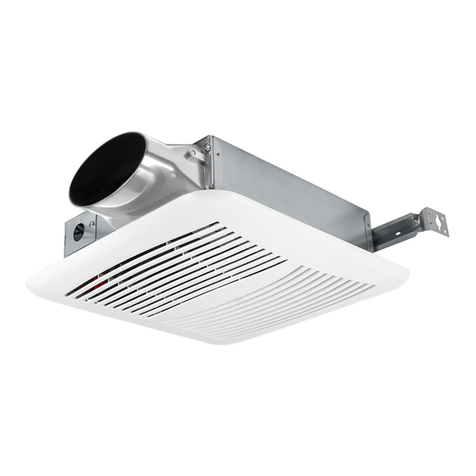
QuFresh QFDC User manual

TM
IMPORTANT INSTRUCTIONS - OPERATING MANUAL
INSTRUCTIONS IMPORTANTES – MANUEL D’OPÉRATION
QFDC and FDC
Inline Fan
Ventilateur en série
READ AND SAVE THESE
LIRE ET CONSERVER
INSTRUCTIONS
CES INSTRUCTIONS
READ CAREFULLY BEFORE ATTEMPTING TO ASSEMBLE, INSTALL,
LIRE SOIGNEUSEMENT AVANT DE TENTER D’ASSEMBLER, INSTALLER,
OPERATE OR MAINTAIN THE PRODUCT DESCRIBED. PROTECT
OPÉRER OU DE RÉPARER LE PRODUIT DÉCRIT. PROTÉGEZ VOUS-MÊME
YOURSELF AND OTHERS BY OBSERVING ALL SAFETY INFORMATION.
ET LES AUTRES EN OBSERVANT TOUTE L’INFORMATION DE SÉCURITÉ.
FAILURE TO COMPLY WITH INSTRUCTIONS COULD RESULT IN
FAILLIR ÀSE CONFORMER AUX INSTRUCTIONS PEUT RÉSULTER EN
PERSONAL INJURY AND/OR PROPERTY DAMAGE!
BLESSURE PERSONNELLE GRAVE ET/OU EN DOMMAGE ÀLA PROPRIÉTÉ.
RETAININSTRUCTIONSFORFUTUREREFERENCE.
CONSERVERCESINSTRUCTIONSPOURRÉFÉRENCESFUTURES.
GENERAL SAFETY INFORMATION
INSTRUCTIONS GÉNÉRALES DE SÉCURITÉ
Lors de l’utilisation d’appareils électriques,
When using electrical appliances, basic
des précautions de base doivent toujours être
precautions should always be followed to
suivies pour réduire les risques d’incendie, de choc électrique et
reduce the risk of fire, electric shock and injury to person,
de blessures corporelles, incluant ce qui suit:
including the following:
AVERTISSEMENT : POURRÉDUIRELES
WARNING: TOREDUCETHERISKOFFIRE,ELECTRIC
RISQUESD’INCENDIE,DECHOCÉLECTRIQUEOUDEBLESSURES
SHOCKANDINJURYTOPERSON,OBSERVETHEFOLLOWING:
PERSONNELLESOBSERVERCEQUI SUIT:
a)
Usethisunit onlyinthemanner intendedbythemanufacturer.If youhavequestions,
a)
Utiliser cetteunitéseulement delamanièrepour laquellelefabricant l’aconçu. Si vous
contact themanufacturer.
aviezdesquestions,veuillezcontacter lefabricant.
b)
Beforeservicingor cleaningtheunit,switchpower off at servicepanel andlock the
b)
Avant d’effectuer unserviceoudenettoyer l’unité,couper l’alimentationélectriquedans
servicedisconnectingmeanstoprevent power frombeingswitchedonaccidentally.When
lepanneaudedistributionet verrouiller ledispositif dedéconnexionafind’éviter que
theservicedisconnectingmeanscannot belocked,securelyfastenaprominent warning
l’alimentationnerevienneaccidentellement.Lorsqueledispositif nepeut êtreverrouillé,
device,suchasatag,totheservicepanel.
fixer solidement unavisd’avertissement,tel qu’uneétiquette, aupanneaudedistribution.
AVERTISSEMENT : POURRÉDUIRELES
WARNING: TOREDUCETHERISKOFFIRE,ELECTRIC
RISQUESD’INCENDIE,DECHOCÉLECTRIQUEOUDEBLESSURES
SHOCKANDINJURYTOPERSON,OBSERVETHEFOLLOWING:
PERSONNELLESOBSERVERCEQUI SUIT:
a)
Installationworkandelectrical wiringmust bedonebyqualifiedperson(s)inaccordance
a)
Letravail d’installationet lecâblageélectriquedoivent êtreeffectuéspar une(des)
withall applicablecodesandstandards, includingfire-relatedconstruction.
personne(s)qualifiée(s)enconformitéavectouslescodeset normesapplicables,incluant
b)
Sufficient air isneededfor proper combustionandexhaustingof gasesthroughthe
laconstructionrelativeauxincendies.
flue(chimney)of fuel burningequipment toprevent backdrafting.Followtheheating
b)
Del’air enquantitésuffisanteest requispour labonnecombustionet l’évacuationde
equipment manufacturer’sguidelineandsafetystandardssuchasthosepublishedby
gazpar leconduit (cheminée)provenant d’équipement debrûlageaucombustible
theNational FireProtectionAssociation(NFPA)andtheAmericanSocietyfor Heating,
pour prévenirunrefoulement.Suivrelesdirectivesdufabricant del’équipement de
Refrigeration,andAir ConditioningEngineers(ASHRAE), andthelocal codeauthorities.
chauffageet lesnormesdesécuritétellesquecellespubliéespar laNational Fire
ProtectionAssociation(NFPA)et delaAmericanSocietyfor Heating,Refrigeration,andAir
c)
Whencuttingor drillingintowall or ceiling,donot damageelectrical wiringandother
ConditioningEngineers(ASHRAE),et decellesdesautoritéslocalesducode.
hiddenutilities.
c)
Lorsdecoupeoudeperçagedesmurset plafonds,nepasendommager lefilage
CAUTION: FORGENERALVENTILATINGUSEONLY.DONOTUSE
électriqueet autresutilitéscachées.
TOEXHAUSTHAZARDOUSOREXPLOSIVEMATERIALSANDVAPORS.
ATTENTION : POURUSAGEDEVENTILATIONGÉNÉRALE
d)
Thisunit must begrounded.
EXCLUSIVEMENT.NEPASUTILISERPOURÉVACUERDUMATÉRIELETDES
e)
Toavoidmotorbearingdamageandnoisyand/or unbalancedimpellers,keepdrywall
VAPEURSDANGEREUSESOUEXPLOSIVES.
spray,constructiondust,etc.off power unit.
d)
Cetteunitédoit êtremiseàlaterre.
f)
Readall instructionsbeforeinstallingor usingfan.
e)
Pour éviterdesdommagesauxroulementsdesmoteurset/oudeshélicesbruyantesou
déséquilibrées,empêcherlapoussièredecloisonsèche,poussièredeconstruction,etc.,
g)
For residential installationsonly.
d’atteindrel’unitédepuissance.
h)
Must usesuitableweather hoodwithinsect screentoprotect airintake.
f)
Liretouteslesinstructionsavant d’installer oud’utiliser laventilateur.
WARNING: TOREDUCETHERISKOFFIRE,ELECTRIC
g)
Pour lesinstallationsrésidentiellesseulement.
SHOCK,DONOTUSETHISFANWITHANYSOLID-STATESPEED
h)
Doit utiliser unehotteappropriéecontrelesintempériesavecunécrananti-insectespour
CONTROLDEVICE.
protégerl’entréed’air.
WARNING: DONOTUSEINKITCHENS.
AVERTISSEMENT : PO
URRÉDUIRELESRISQUES
D’INCENDIEOUDECHOCÉLECTRIQUE,NEPASUTILISERCE
WARNING: THEDUCTINGFROMTHISFANTOTHEOUTSIDEOFTHE
VENTILATEURAVECUNRÉGULATEURDEVITESSEÉLECTRONIQUE.
BUILDINGHASASTRONGEFFECTONTHEAIRFLOW,NOISEANDENERGY
USEOFTHEFAN.USETHESHORTEST,STRAIGHTESTDUCTROUTINGPOSSIBLEFOR
AVERTISSEMENT : NEPASUTILISERDANSLESCUISINES.
BESTPERFORMANCE,ANDAVOIDINSTALLINGTHEFANWITHSMALLERDUCTSTHAN
RECOMMENDED.INSULATIONAROUNDTHEDUCTSCANREDUCEENERGYLOSSAND
AVERTISSEMENT : LACANALISATIONDECEVENTILATEURÀ
L’EXTÉRIEURDUBÂTIMENTAUNEFFETIMPORTANTSURLEFLUXD’AIR,LEBRUIT
INHIBITMOLDGROWTH.FANSINSTALLEDWITHEXISTINGDUCTSMAYNOTACHIEVE
ETLACONSOMMATIOND’ÉNERGIEDUVENTILATEUR.UTILISEZLAROUTEDECANALISATION
THEIRRATEDAIRFLOW.
LAPLUSCOURTEETLAPLUSDROITEPOSSIBLEPOURUNEMEILLEUREPERFORMANCE,
ETÉVITEZD’INSTALLERLEVENTILATEURAVECDESCONDUITSPLUSPETITSQUE
RECOMMANDÉ.L’ISOLATIONAUTOURDESCONDUITSPEUTRÉDUIRELAPERTED’ÉNERGIE
ETEMPÊCHERLEDÉVELOPPEMENTDEMOISISSURES.ILSEPEUTQUELESVENTILATEURS
INSTALLÉSAVECDESCONDUITSEXISTANTSN’ATTEIGNENTPASLEURDÉBITD’AIRNOMINAL.
6727924Rev.G5-20
1of 8
Patent: 11,079,126 and 11,306,932
Date: March 31, 2022

Intake Ducting
Conduit d’admission
Outlet Ducting
Conduit de sortie
Air Flow
Flux d’air
Test Port / Port d’essai
AirFlow/ Fluxd’air
Figure 4
.
ThreadedRod
Tigefiletée
Bracket
Housing
Support
Châssis
Figure 3
INSTALLATION INSTRUCTIONS
INSTRUCTIONS D’INSTALLATION
ATTENTION: VOUSASSURERQUEL’ALIMENTATIONEST
CAUTION: MAKESUREPOWERISSWITCHEDOFFATSERVICE
COUPÉEAUPANNEAUDESERVICEAVANTDECOMMENCERL’INSTALLATION.
PANELBEFORESTARTINGINSTALLATION.
SECTION 1
SECTION 1
Préparation du Ventilateur
Preparing the Fan
1.
Sortirleventilateur desaboiteet confirmer quetouteslespiècessont présentes. Enplus
1.
Unpackfanfromthecartonandconfirmthat all piecesarepresent.Inadditiontothefan
duventilateur vousdevriezavoir:
youshouldhave:
2-Assemblagedecollier (attaché) 2- TraversesdeMontage(attaché)
2- CollarAssembly(attached)
2- MountingBrackets(attached)
1- Contrôleur (attaché)(noninclusaveclemodèleF130D)
1- Controller (attached)(not includedwithF130Dmodel)
1- Feuillet d’instructions/ sécurité
1- Instruction/SafetySheet
2.
Choisirunemplacementpourvotreventilateur.Pourgarantirlameilleurequalitéd’airet
performanceacoustique,ilestrecommandéquelalongueurdelacanalisationetlenombrede
2.
Choosethelocationforyourfan.Toensurethebest airandsoundperformance,itis
coudessoientréduitsauminimum,quelerayondechaquecoudesoitaussigrandquepossible
recommendedthatthelengthofductingandthenumberof elbowsbekept toaminimum,
pourl’installation,etquedesconduitsrigidesisoléssoientutilisés.Ceventilateurnécessitera
theradiusofeachelbowbeaslargeaspossiblefortheinstallation,andthatinsulatedhard
aumoins12podedégagementdansleplafondoulemur.Leventilateursemonteàl’aidedes
ductingbeused.Thisfanwillrequireat least 12" of clearanceintheceilingorwall.Thefan
supportsdemontagefournisoupeutêtremontéensurfacesurunmurouunplafond.
mountsusingtheprovidedmountingbracketsorcanbesurfacemountedtoawallorceiling.
REMARQUE:Leventilateurdoitêtreinstallédansunendroitfacilementaccessibleunefoisinstallé.
NOTE:Thefanmust beinstalledintoalocationthat canbeeasilyaccessedonceinstalled.
3. Aucunmatérielamortissantdevibrationssupplémentairen’estnécessairepourceventilateur.
3.
Noadditional vibrationdeadeningmaterialsareneededforthisfan.
SECTION 2
Stud/Joist
Anchor/Ancre
Monter le ventilateur
SECTION 2
Montant / Solive
Mounting the Fan
1. Vérifiezqueleventilateur est positionnédemanièreàcequeleflux
d’air soit danslabonnedirection.
1.
Confirmthefanispositionedsotheairflowisinthecorrect
2a. Montageensurface: Localisezaumoinsungoujonouunesolive.
direction.
Screws/Vis
Placezleventilateur enpositiondesortequelesupport demontage
2a.
SurfaceMounting:Locateat least onestudor joist.Placethefan
soit centrésur legoujonoulasoliveet marquezl’emplacement des
inpositionsothat themountingbracket iscenteredonthestud
quatre(4)trous.Retirezleventilateur et installezdesancragesmuraux
or joist andmakethelocationfor thefour (4)holes.Removethe
/ deplafondcorrectement dimensionnéspour lestrousqui nevont pas
fanandinstall properlyratedwall/ceilinganchorsfor theholes
directement dansunesoliveoulegoujon.Positionnezleventilateur en
Figure 1
that donot godirectlyintoajoist or stud. Positionfaninplace
placeet fixez-leavec desvis(noninclus)(Figure1).
andsecurewithscrews(not included)(Figure1).
2b. Montagesur unesolive:Installezdeux- 2x4embases(non
inclus)entrelessolives.Positionnezleboîtierduventilateur surles
2b. MountingtoaJoist:Install two- 2x4headers(not included)
12"
embaseset fixezlessupportsdemontageàl’aidedesvis(noninclus)
betweenthejoists.Positionthefanhousingontopof the
Bracket
12po
(Figure2).
headersandsecurethemountingbracketswithscrews(not
Support
included)totheheader (Figure2).
2c. Montagedelabarredesuspension::soulevezl’unitésurles
Joist / Solive
tigesfiletéeset fixez-laenplaceàl’aidedematériel approprié(non
2c.
HangingBar Mounting:Lift unit upontothethreadedrods
inclus)(Figure3).
2x4Header/ Embases
andsecureinplaceusingappropriatehardware(not included)
Figure 2
(Figure3).
SECTION 3
Conduit
SECTION 3
NOTE:UNCONDUITPLUSRIGIDEDE6POOUPLUSESTRECOMMANDE
Ducting
POURUNEMEILLEUREPERFORMANCE.
NOTE:6" ORLARGERRIGIDDUCTISRECOMMENDEDFORBEST
ATTENTION: TOUSLESCONDUITSDOIVENTÊTRE
PERFORMANCE.
CONFORMESAVECLESCODESDUBATIMENTLOCAUXET
NATIONAUX.
CAUTION: ALLDUCTINGMUSTCOMPLYWITHLOCAL
ANDNATIONALBUILDINGCODES.
REMARQUE:Lacanalisationdeceventilateuràl’extérieurdubâtiment a
uneffet important sur lefluxd’air,lebruit et laconsommationd’énergie
NOTE:Theductingfromthisfantotheoutsideof thebuildinghasastrongeffect ontheair
duventilateur.Utilisezlaroutedecanalisationlapluscourteetlaplusdroitepossiblepour
flow,noiseandenergyuseof thefan.Usetheshortest,straightest duct routingpossible
unemeilleureperformance,et évitezd’installerle ventilateuravecdesconduitspluspetits
for best performance,andavoidinstallingthefanwithsmaller ductsthanrecommended.
querecommandé.L’isolationautourdesconduitspeut réduirelaperted’énergieetempêcher
Insulationaroundtheductscanreduceenergylossandinhibit moldgrowth.Fansinstalledwith
ledéveloppement demoisissures.Il sepeut quelesventilateursinstallésavecdesconduits
existingductsmaynot achievetheir ratedair flow.
existantsn’atteignent pasleurdébitd’airnominal.
WARNING: MAKESURETHEFRESHAIRINTAKEPORTCOMPLIESWITH
AVERTISSEMENT: ASSUREZ-VOUSQUELEPORTD’ADMISSION
ALLLOCALANDNATIONALCODESANDISLOCATEDATLEAST6FEETAWAY
D’AIRFRAISESTCONFORMEÀTOUSLESCODESLOCAUXETNATIONAUXETSE
FROMSOURCESOFCONTAMINATIONSUCHASBUTNOTLIMITEDTO:DRYER,FURNACEOR
TROUVEÀAUMOINS6PIEDSDESSOURCESDECONTAMINATIONTELLESQUE:SÉCHEUSE,
FOUROUASPIRATEURCENTRAL,APPAREILSÀGAZTELSQUEBARBECUE,BACSÀ
CENTRALVACUUMEXHAUSTS,GASAPPLIANCESSUCHASBBQGRILLS,GARBAGEBINS
DÉCHETSOUD’AUTRESPORTSD’ÉCHAPPEMENT.
OROTHEREXHAUSTPORTS.
REMARQUE:Pourassurerunfonctionnementsilencieuxdesventilateursenligneetàdistance,
NOTE:Toensurequietoperationof in-lineandremotefans,eachfanshallbeinstalledusing
chaqueventilateurdoitêtreinstalléenutilisantlestechniquesd’atténuationsonoreappropriéesà
soundattenuationtechniquesappropriatefortheinstallation.Thiscantypicallybeachievedby
l’installation.Ceci peutgénéralement êtreréaliséeninstallant desconduitsflexiblesisolésentre
installinginsulatedflexibleductingbetweentheexhaustorsupply
la(les)grille(s)d’évacuationd’airet leventilateur.
grille(s)andthefan.
1. Raccordezlesconduitsaucollet duconduit duventilateur
1.
Connect theductingtothefan’sduct collar (Figure4).
(Figure4). Scellezlesconduitsdansleboîtier àl’aided’un
Seal ductingtohousingwithappropriatelyratedtape.Use
rubanapproprié.Utilisezdesvisoudespincesappropriées
screwsor suitableclampstosecureinplace.Makesure
pour lesfixer enplace.Assurez-vousquel’entréed’airfraisest
thefreshairintakeisconnectedtoaproperlyinstalled
raccordéeàunorificed’admissioncorrectement installé,qui est
intakeport that isasuitableweather hoodwithinsect
unehottecontrelesintempériesavecunécrananti-insectes
screentoprotect airintake.It isrecommendedthat low
pour protéger l’entréed’air. Il est recommandéd’utiliser des
restrictionterminationfittingsbeused.
raccordsd’extrémitéàfaiblerestriction.
2. Assurez-vousquelesjointsdesconduitset lespénétrations
2.
Ensureduct jointsandexteriorpenetrationsaresealedwith
extérieuressont scellésavecdumasticoutout autrematériau
caulkorothersimilarmaterial tocreateanair-tightpathto
similairepour créer unpassaged’airétancheafindeminimiser laperteoulegaindechaleur
minimizebuildingheat lossorgainandtoreducethepotentialforcondensation.Place/wrap
et réduirelerisquedecondensation.Placez/ enveloppezl’isolant autour duconduit et / ou
insulationaroundductand/orfaninordertominimizepossiblecondensationbuildupwithin
ventilateur afindeminimiser lapossibilitéd’accumulationdecondensationàl’intérieurdu
theduct,aswellasbuildingheatlossorgain.
conduit,ainsi quelaperteoulegaindechaleur.
NOTE:At thebaseof theduct adapter,thereisasmall diameter test port holecoveredwith
REMARQUE:Àlabasedel’adaptateur deconduit,il yaunorificedeport d’essai depetit
aplasticcap.Makesurethetest port isnot coveredupwiththeductingsothat it canbe
diamètrerecouvertd’uncapuchonenplastique.Assurez-vousqueleport d’essai n’est pas
accessedfor pitot tubetesting.Toaccesstheport,removetheport cover andinsert tube.
recouvert par lacanalisation,desortequ’il soit accessiblepour tester letubedepitot.Pour
accéder auport,retirezlecouvercleduport et insérezletube
6727924Rev.G5-20
2of 8

3
0
4
0
5
0
6
0
7
0
8
0
9
0
1
0
0
1
1
0
1
2
0
1
3
0
Supply from house
Alimentation provenant de
la résidence
Fan / Ventilateur
Filter / Filtre
3
0
4
0
5
0
6
0
7
0
8
0
9
0
1
0
0
1
1
0
1
2
0
1
3
0
Figure 8
Receptacle
Figure 9
Black/ Noir
Black/ Noir
Neutral (White)
Neutral (White)
Neutre(Blanc)
Neutre(Blanc)
Ground(Greenor Bare)
Green/Vert
Miseàlaterre(vert ounu)
Green/Vert
Byothers/ Par d’autres
Figure 6
SECTION 4
SECTION 4
Câblage
Wiring
ATTENTION:VOUSASSURERQUEL’ALIMENTATION
CAUTION: MAKESUREPOWERISSWITCHEDOFFATSERVICE
ESTCOUPÉEAUPANNEAUDESERVICEAVANTDECOMMENCER
PANELBEFORESTARTINGINSTALLATION.
L’INSTALLATION.
CAUTION: ALLELECTRICALCONNECTIONSMUSTBEMADE
ATTENTION:TOUTESLESCONNEXIONSDOIVENTÊTRE
INACCORDANCEWITHLOCALCODES,ORDINANCES,ORNATIONAL
FAITESENCONFORMITÉAVECLESCODESÉLECTRIQUESLOCAUXOU
ELECTRICALCODE.IFYOUAREUNFAMILIARWITHMETHODSOFINSTALLINGELECTRICAL
NATIONAUX. SI VOUSN’ÊTESPASFAMILIERAVECLES
WIRING,SECURETHESERVICESOFAQUALIFIEDELECTRICIAN.
Screw/ Vis
MÉTHODESD’INSTALLATIONDECÂBLAGEÉLECTRIQUE,
NOTE:Thisunit includesasideaccesspanel for wiringthat does
RECOURREZAUXSERVICESD’UNÉLECTRICIENQUALIFIÉ.
not requiretheremoval of thefan’sblower assembly.
WireCompartment
GroundScrew
REMARQUE:Cetteunitépossèdeunpanneaud’accèslatéral
Cover
Visausol
pour lecâblagequi nerequiert pasl’enlèvement del’assemblage
1.
Removethewirecompartment cover screwandplace
Couvercledu
delasoufflanteduventilateur.
cover inasecureplace(Figure5).
Compartiment de
1. Enlever lavisducouvercleducompartiment àcâblageet
Câblage
2.
Pull thelooseblack,whiteandgreenwiresout fromthe
mettrececouvercledansunendroit fiable(Figure5).
wirecompartment (additional wireswill bepresent).Install
Figure 5
2. Retirezlesfilsnoirs,blancset vertsdétachésducompartiment
anapprovedelectrical connector tothewirecompartment
descâbles(desfilssupplémentairesserontprésents).Installezun
cover (not included).Runablack(hot),white(neutral), and
connecteurélectriqueapprouvésurlecouvercleducompartiment
agreenor baregroundwirefromthesupplythroughthe
descâbles(noninclus).Faitespasserunfilnoir(chaud),blanc
electrical connector.Connect all wiresfromthesupplyto
(neutre)et unfildeterrevertounudel’alimentationàtraversle
theircorrespondingwireswithinthewirecompartment
connecteurélectrique.Connecteztouslesfilsdel’alimentationà
(Figure6).Useapprovedmethodsfor all connections.
leursfilscorrespondantsdanslecompartimentdesfils(Figure6).
3.
Carefullytuckwiresbackinsidewirecompartment and
Utiliserdesméthodesapprouvéespourtouteslesconnexions.
replacewirecompartment cover securingwiththescrew
3. Regrouper soigneusement lesfilsàl’intérieur du
that wasremovedearlier.
compartiment pour leraccordement et replacer lecouvercledu
compartiment enlefixant aveclavisqui fut enlevéeprécédemment.
SECTION 5
Setting the Speed
SECTION 5
Réglage de la vitesse
1.
Removethescrewssecuringtheaccesspanel cover inplace
1. Retirezlesvisqui retient lecouvercledupanneaud’accèset
andopenthecover togainaccess.Locatethespeedcontrol
Screw
Screw
ouvrezlecouverclepour yaccéder.Localisezlepanneaudecontrôle
panel insidetheunit (Figure7).
Vis
Vis
devitesseàl’intérieur del’unité(Figure7).
2.
DeterminetheCFMrequired.Theunit canbeset from30CFM
2. DéterminezleCFMrequis.L’unitépeut êtrerégléede30CFMà
to130CFMinincrementsof 10CFM(Figure8).
Figure 7
130CFMpar incrémentsde10CFM(Figure8).
SECTION 6
SECTION 6
Motorized Damper
Amortisseur motorisé
Anoptional motorizeddampercanbeconnectedtotheunit.Thedamperis
Unamortisseur motoriséoptionnel peut êtreconnectéàl’unité.L’amortisseur
connect viaa24Vtransformerthat plugsintothereceptacleintheunit(Figure9).
est connectéviauntransformateur 24Vqui sebranchedansleréceptaclede
l’unité(Figure9).
NOTE:Makesuretoreferencetheinstructionsincludedwiththemotorized
damper beforeinstallingoroperating.
REMARQUE:Assurez-vousdeconsulter lesinstructionsfourniesavec
l’amortisseur motoriséavant del’installer oudel’utiliser.
Operation
Operation
1.
Wheninstalledtheoutlet will beenergizedanytimetheunit isrunning.
1. Unefoisinstallée,lapriseseraénergiséechaquefoisquel’unitéest
Thiswill inturnopenthedamper.Whentheunit stopsrunning,the
enmarche.Celaouvriraàsontour l’amortisseur.Lorsquel’unités’arrête,
damper will close.
l’amortisseur sefermera.
SECTION 7
SECTION 7
Optional Air Filter
Filtre à air optionnel
Anair filter (availableseparately)canbeaddedtothisunit toprovideadditional
Unfiltreàair(disponibleséparément)peut êtreajoutéàcetteunitépour fournir
filtrationof theintakeair.Theunitwill accept a10” x10” x2” filter.Toinstall:
unefiltrationsupplémentairedel’aird’admission.L’unitéaccepteraunfiltrede
10pox10pox2po.Pourinstaller:
NOTE:Addinganair filter will decreasetheairflowof theunit.Youwill need
toincreasetheCFMselectedinSECTION5toaccount for thedecreased
REMARQUE:L’ajout d’unfiltreàair diminueledébit d’air del’appareil.Vous
air flow.Filtersmust bechangedregularly.Refer tothefilter manufacturer’s
devrezaugmenter leCFMsélectionnédanslaSECTION5pour tenircompte
recommendationstodeterminehowoftenthefilter shouldbechanged.
dudébit d’airdiminué.Lesfiltresdoivent êtrechangésrégulièrement.
Reportez-vousauxrecommandationsdufabricant dufiltrepour
1.
Removethescrewssecuringtheaccesspanel cover in
déterminer lafréquenceàlaquellelefiltredoit êtrechangé.
placeandopenthecover togainaccesstothecontrols
1. Retirezlesvisqui retient lecouvercledupanneaud’accèset
andfilter area.
ouvrezlecouverclepour accéder auxcommandeset àlazone
2.
Ensurethefilter isfacingthecorrect wayandslidethefilter
AirFlow
dufiltre.
Fluxd’air
intotheslot inthehousing.Makesurethefilter isseatedall
2. Assurez-vousquelefiltreestorientédanslebonsensetfaites
thewaytothebottomof thehousing(Figure10).
Screw
Screw
glisserlefiltredanslafenteduboîtier.Assurez-vousquelefiltre
Vis
Vis
3.
Closetheaccesspanel andreinstall thescrewholdingthe
estbienenplacejusqu’aufondduboîtier(Figure10).
accesspanel inplace.
3. Fermezlepanneaud’accèset réinstallezlavisqui maintient le
panneaud’accèsenplace.
Figure 10
SECTION 8
Completing the Installation
SECTION 8
Complétion de l’installation
NOTE:Whenfanismountedinlineandnopenetrationismadeintounconditionedspaces,there
isnoneedtouseasealant appropriatefor contact withthebuildingmaterialspresent andfor
REMARQUE:Lorsqueleventilateur est montéenligneet qu’aucunepénétrationn’est faite
thetemperaturerequirementsof theinstallationtoprevent air leakagefromunconditioned
dansdesespacesnonconditionnés,il n’est pasnécessaired’utiliser unscellant appropriépour
lecontact aveclesmatériauxdeconstructionprésentset pour lesexigencesdetempérature
spaces.Additional material (backingrod,ceilingmaterial)arealsonot required.
del’installation.Desmatériauxsupplémentaires(tigedesupport,matériaudeplafond)nesont
NOTE:Thisunit isequippedwithawiremeshinsect screen.Confirmthat thescreenisinstalled
pasnonplusnécessaires.
ontheinsideof theunit ontheinlet ductingside.
REMARQUE:Cetteunitéest équipéed’ungrillagepour moustiquaire.Assurez-vousquele
grillageest installéàl’intérieur del’unité,ducôtédesconduitsd’entrée.
6727924Rev.G5-20
3of 8

ON/ OFF/
CONFIGURE
ENERGYSAVING
(MARCHE/ARRÊT/
ÉCONOMIED’ÉNERGIE)
Larger
TopTab
Grande
languette
supérieure
Screen
Grillage
BaseTab
Languettebase
Figure 11
SmallerTopTab/ Petitelanguettesupérieure
Screen
Screen
Grillage
Grillage
Figure 12
UP(HAUT)
DOWN(BAS)
1.
If thescreenisnot inplace,insert thescreenintothetabat
thebaseof theunit (makesurethewider sideof thescreenis
runningsidetosideinsidetheunit)(Figure11).
2.
Slidethescreentothesidewiththelarger toptabmakingsure
thescreenfitsbehindthetab(Figure11).
3.
Slidethescreenbackover towardsthesmallertoptabmaking
surethescreenfitsbehindthetab(Figure12).
4.
Confirmthat thescreenisbeingheldinplacebybothtoptabs
(Figure12).
5.
Closetheaccesspanel andreinstall thescrewsholdingthe
accesspanel inplace.
6.
Restorepower andtest your installation.
SECTION 9 (QFDC model)
Setting the Controller
Theunit mountedcontroller monitorstemperatureandhumidity
of incomingairandallowstheinstaller toconfigureoptimal
ventilation.
Withpower totheunit turnedon, theinitial screenwill show“OFF”.
1. Si legrillagen’est pasenplace, insérezlegrillagedansla
languettesituéeàlabasedel’unité(assurez-vousquelecôtéleplus
largedugrillageest latéral àl’intérieur del’unité)(Figure11).
2. Faitesglisser legrillagesurlecôtéaveclaplusgrandelanguette
supérieureenvousassurant quelegrillages’adaptederrièrela
languette(Figure11).
3. Faitesglisserlegrillageverslapluspetitelanguettesupérieureen
vousassurantquelegrillageseplacederrièrelalanguette(Figure12).
4. Confirmezquelegrillageest maintenuenplacepar lesdeux
languettessupérieures(Figure12).
5 Fermezlepanneaud’accèset réinstallezlesvisqui maintient le
panneaud’accèsenplace.
6. Restaurer l’alimentationet tester votreinstallation.
SECTION 9 (QFDC modelo)
Réglage du contrôleur
Lecontrôleur montésur l’unitésurveillelatempératureet l’humidité
del’air entrant et permet àl’installateur deconfigurer une
ventilationoptimale.
Lorsquel’appareil est allumé, l’écraninitial affiche«ARRÊT».
Appuyezsur lebouton«MARCHE»pourafficherlatempérature
Pressthe“ON” buttontoshowthecurrent temperatureand
et l’humiditéactuelles. Enappuyant sur lebouton«MARCHE»,
humiditycondition.Bypressingthe“ON” button,theunit will
l’appareil s’allumepour undébit d’aircontinuenutilisant les
turnonfor continuousairflowusingtheCFMsettingsfrom
paramètresCFMdelaSECTION5Réglagedelavitesse.
SECTION5SettingtheSpeed.
MODE D’ÉCONOMIE D’ÉNERGIE (QFDC SOLO)
REMARQUE:Cet appareil est équipéd’unmoded’économied’énergiequi vouspermet
deconfigurer leslimitessupérieureet inférieuredetempératureet d’humidité.Enfixant
ceslimites,vouscontribuerezàempêcherleschangementsextrêmesdetempératureou
d’humiditéd’entrer dansl’espacedevie.
ENERGY SAVING MODE (QFDC ONLY)
NOTE:Thisunit isequippedwithanEnergySavingModethat allowsyoutoconfigureupper
andlower limitsfor temperatureandhumidity.Bysettingtheselimits, youwill helpprevent
extremetemperatureor humiditychangesfromenteringintothelivingspace.
1. If youhavenot alreadypressedthe“ON” buttoninsteponeof thissection, dosonow.
1. Si vousn’avezpasencoreappuyésur lebouton«MARCHE»àlapremièreétapedecette
section,faites-lemaintenant.Appuyezunefoissurlebouton«CONFIGURE»et l’écran
affichera«C»et «UnitéTemp»sur lecôtédroit.
2. AppuyezsurleboutonhautoubaspourafficherlatempératureendegrésFahrenheitouCelsius.
3. Appuyezànouveausurlebouton«CONFIGURE»pourréglerlatempératurelimitesupérieure.
C’estlatempératureoùlorsquel’airextérieurarrivedanslamaison,leventilateurs’arrêteet
passeenmoded’échantillonnage.Vousverrez«Limitesupérieure»et«Température»surle
côtédroit.Utilisezlesboutons«HAUT»et«BAS»pourajusterlatempérature.
4. Appuyezànouveausurlebouton«CONFIGURE»pourréglerlalimitesupérieureduniveau
d’humidité.C’estleniveaud’humiditéoù,lorsquel’airextérieurarrivedanslamaison,le
ventilateurs’arrêteetpasseenmoded’échantillonnage.Vousverrez«Limitesupérieure»et«
Humidité»surlecôtédroit.Utilisezlesboutons«HAUT»et«BAS»pourajusterlatempérature.
5. Appuyezànouveausurlebouton«CONFIGURE»pour réglerleniveaudetempérature
inférieur.C’est latempératureoùlorsquel’air extérieur entrant danslamaisontombeen
dessous,leventilateur s’arrêteet passeenmoded’échantillonnage.Vousverrez«Limite
inférieure»et «Temperature»sur lecôtédroit.Utilisezlesboutons«HAUT»et «BAS»
pour ajuster latempérature.
6. Appuyezànouveausurlebouton«CONFIGURE» pourréglerleniveaud’humiditélimite
inférieure.C’est leniveaud’humiditéqui,lorsquel’airextérieurentrantdanslamaisontombe
endessous,leventilateurs’arrêteetpasseenmoded’échantillonnage.Vousverrez“Limite
inférieure” et“Humidité” sur lecôtédroit.Utilisezlesboutons«HAUT»et «BAS»pourajuster
latempérature.Sivousréglezceparamètresur0ou“LO”,leniveauderéglagedel’humidité
estannulé.Celapeut êtrenécessairedansleszonesàtrèsfaiblehumiditédupays.
7. Appuyezsurlebouton«CONFIGURE»jusqu’àcequ’ilrevienneàl’écranprincipal.Vousverrez
«MARCHE»danslecoinsupérieurgauchedel’écran.Àcestade,l’informationaétésuvegardée.
SECTION 10 (FDC Modelo)
Utilisation du contrôleur
1. ModeÉconomied’énergie:Pour passerenmodeÉconomied’énergie,appuyezsur
lebouton«MARCHE/ARRÊT/ ÉCONOMIED’ÉNERGIE»jusqu’àceque«Économie
d’énergie»apparaissesur lecôtégauchedel’écran.LemodeÉconomied’énergieactive
lesparamètresconfigurésdanslaSECTION9ModeÉconomied’énergie.
2. Lorsquel’appareil est allumé,l’écranafficheralesconditionsactuelles(températureet
niveaud’humidité)ainsi ques’il est enmodeÉconomied’énergieounon. D’autresicônes
/ informationspouvant figurer àl’écranincluent:
L’icôneduventilateur apparaît lorsqueleventilateur est allumé.
«HI° F»apparaît si latempératured’entréeest supérieureà150° F.
«Lo° F»apparaît si latempératured’entréeest inférieureà15 ° F.
«Lo%»apparaît si l’humiditéd’entréeest inférieureà10%.
Pressthe“CONFIGURE” buttononceandthedisplaywillshowa“C” and“TempUnit” on
theright handside.
2. Presstheupor downbuttontodisplaythetemperatureinFahrenheit or Celsius.
3. Pressthe“CONFIGURE” buttonagaintoset theupper limit temperature.Thisisthe
temperaturethat whentheoutsideaircomingintothehomeexceeds,thefanwill stop
andenter samplingmode.Youwillsee“UpperLimit” and“Temperature” ontheright
handside.Usethe“UP” and“DOWN” buttonstoadjust thetemperature.
4. Pressthe“CONFIGURE” buttonagaintoset theupper limit humiditylevel.Thisisthe
humiditylevel that whentheoutsideaircomingintothehomeexceeds,thefanwill stop
andenter samplingmode.Youwill see“Upper Limit” and“Humidity” ontheright hand
side.Usethe“UP” and“DOWN” buttonstoadjust thetemperature.
5. Pressthe“CONFIGURE” buttonagaintoset thelower temperaturelevel.Thisisthe
temperaturethat whentheoutsideaircomingintothehomefallsbelow,thefanwill stop
andenter samplingmode.Youwillsee“LowerLimit” and“Temperature” ontheright
handside.Usethe“UP” and“DOWN” buttonstoadjust thetemperature.
6. Pressthe“CONFIGURE” buttonagaintoset thelower limit humiditylevel.Thisisthe
humiditylevel that whentheoutsideaircomingintothehomefallsbelow,thefanwill
stopandenter samplingmode.Youwillsee“Lower Limit” and“Humidity” ontheright
handside.Usethe“UP” and“DOWN” buttonstoadjust thetemperature. Settingthisto0
or“LO” will overridethehumidityset level.Thismaybenecessaryinverylowhumidity
areasof thecountry.
7. Pressthe“CONFIGURE” buttonuntilit returnstothemainscreen.Youwill see“ON” in
thetopleft corner of thedisplay.At thispoint,theinformationhasbeenstored.
SECTION 10 (QFDC Model)
Using the Controller
1. EnergySavingsMode:ToentertheEnergySavingsmode,pressthe“ON/OFF/ENERGY
SAVINGS” Buttonuntil“EnergySavings” appearsontheleft sideof thedisplay.Energy
SavingsmodeengagesthesettingsconfiguredinSECTION9EnergySavingMode.
2. Whentheunit ison,thedisplaywill showthecurrent conditions(temperatureand
humiditylevel)aswell asif it isinEnergySavingsmodeor not.Other icons/information
that maybeonthedisplayinclude:
Faniconappearswhenthefanison.
“HI°F
” appearsif theintaketemperatureisabove150°F.
“Lo°F
” appearsif theintaketemperatureisbelow 15°F.
“Lo%” appearsif theintakehumidityisbelow10%.
3.
Unitédechauffageoptionnelle:Uneunitédechauffageoptionnelleest disponible
3.
Optional Heater Unit:Anoptional heater unit isavailablefor climatesthat theair coming
pour lesclimatsoùl’air entrant dansl’unitétombeendessousde54° F. Pour installer
intotheunit fallsbelow54°F.Toinstall theunit,followthedirectionthat areincluded
l’unité,suivezlesinstructionsfourniesaveccetteunité.L’écranafficherauneicônede
withthat unit.Thedisplaywill showathermometericonwitheithera“1” or“12” when
thermomètreavecun«1»ou«12»lorsquelaplagedetempératureest àunniveau
thetemperaturerangeisat alevel wheretheheatingelement wouldcomeonif present.
oùl’élément chauffant s’allumes’il est présent.Étape1- «1»s’allumelorsquela
Stage1-“1” turnsonwhentheintakeairtemperatureisbetween39°Fand54°F.Stage
températuredel’aird’admissionsesitueentre39° Fet 54° F.Lesétapes1et 2«12»
1and2“12” turnonwhentheintakeairtemperatureisbetween33°Fand39°F.
s’allument lorsquelatempératuredel’aird’admissionsesitueentre33° Fet 39° F.
4.
Torestorethefactorysetting,makesuretheunit isinthe“OFF” setting.Holdboththe
4.
Pour restaurer leréglaged’usine,assurez-vousquel’appareil est réglésur «ARRÊT».
“UP” and“DOWN” buttonsfor approximately5seconds.The“OFF” onthedisplaywill
Maintenezlesboutons«HAUT»et «BAS»pendant environ5secondes. L’indication«
flashtoconfirmthesettingshavebeenrestored.
ARRÊT»sur l’affichageclignotepour confirmer quelesréglagesont étérestaurés.
6727924Rev.G5-20
4of 8

SECTION 11
SECTION 11
Utilisation et entretien
Use and Care
CAUTION: MAKESUREPOWERISSWITCHEDOFFATSERVICE
ATTENTION : VOUSASSURERQUEL’ALIMENTATION
PANELBEFORESERVICINGTHEUNIT.
ESTCOUPÉEAUPANNEAUDESERVICEAVANTDECOMMENCER
L’INSTALLATION.
1.
CleaningtheFanAssembly:Wipeall partswithadryclothor gentlyvacuumthefan.
1.
Nettoyagedel’assemblageduventilateur :Nettoyer touteslespartiesàl’aided’un
NEVERIMMERSEELECTRICALPARTSINWATER.
chiffonsecoupasser délicatement l’aspirateur sur leventilateur.NEJAMAISIMMERGER
NOTE:If younoticealargeamount of insectsanddebrisintheinsect filter, thiscouldbeasign
LESPARTIESÉLECTRIQUESDANSL’EAU.
that theintakeweather hood(roof capor wall cap)might becompromisedandneedrepair or
REMARQUE:Sivousremarquezunegrandequantitéd’insectesetdedébrisdanslefiltreàair,
replacing.
celapourraitindiquerquelahotted’aspiration(capuchondetoitoucapuchonmural)pourraitêtre
2.
Optional AirFilter:If anoptional air filter isinstalled,it shouldbecheckedeverymonth
compromiseetnécessiteruneréparationouunremplacement.
andreplacedat least onceevery3months.ReversetheinstructionsintheSECTION8of
2.
Filtreà airoptionnel : Si unfiltreàair optionnel est installé,il doit êtrevérifiétous
theseinstructionstoremovefilter.
lesmoiset remplacéaumoinsunefoistousles3mois.Inversezlesinstructionsdela
SECTION7decesinstructionspour retirerlefiltre.
CALIFORNIA RESIDENTS ONLY:
RÉSIDENTS DE LA CALIFORNIE UNIQUEMENT :
WARNING: THISPRODUCTCANEXPOSEYOUTOACHEMICAL[OR
CHEMICALS] KNOWNTOTHESTATEOFCALIFORNIATOCAUSECANCER.
AVERTISSEMENT :CEPRODUITPEUTVOUSEXPOSERÀUN
PRODUITCHIMIQUE[OUÀDESPRODUITSCHIMIQUES] CONNU(S) PARL’ÉTATDE
WARNING: THISPRODUCTCANEXPOSEYOUTOACHEMICAL[OR
LACALIFORNIEPOURCAUSERLECANCER.
CHEMICALS] KNOWNTOTHESTATEOFCALIFORNIATOCAUSEREPRODUCTIVE
AVERTISSEMENT : CEPRODUITPEUTVOUSEXPOSERÀUN
TOXICITY.
PRODUITCHIMIQUE[OUÀDESPRODUITSCHIMIQUES] CONNU(S) PARL’ÉTAT
DELACALIFORNIEPOURCAUSERLATOXICITÉENVERSLESFONCTIONSDELA
LIMITED WARRANTY
REPRODUCTION.
WHATTHISWARRANTYCOVERS:Thisproduct iswarrantedagainst defectsinworkmanship
and/ormaterials.
GARANTIE LIMITÉE
HOWLONGTHISWARRANTYLASTS:Thiswarrantyextendsonlytotheoriginal purchaser of
CEQUECOUVRECETTEGARANTIE:Ceproduit est garanti contretout vicedefabricationou
theproduct andlastsfor five(5)yearsfromthedateof original purchaseor until theoriginal
dematière.
purchaser of theproduct sellsor transferstheproduct,whichever first occurs.
COMBIENDETEMPSCETTEGARANTIEDURE:Cettegarantieserapporteseulementàl’acheteur
original duproduitetdurependant cinq(5)annéesdeladatedel’achat originaloujusqu’àceque
WHATQuFresh WILLDO:Duringthewarrantyperiod, Air Kingwill, at itssoleoption, repairor
l’acheteuroriginalduproduitvendoutransfèreleproduit,celuiqui seproduitenpremier.
replaceanypart or partsthat provetobedefectiveor replacethewholeproduct withthesame
or comparablemodel.
QUEFERAQuFresh :Aucoursdelapériodedegarantie, AirKing, àsonchoix, répareraou
remplaceran’importequellepartieoupiècesqui s’avèrent défectueusesouremplacerale
WHATTHISWARRANTYDOESNOTCOVER:Thiswarrantydoesnot applyif theproduct was
produit entier par lemêmemodèleouunmodèlecomparable.
damagedor failedbecauseof accident,improper handlingor operation,shippingdamage,
abuse,misuse,unauthorizedrepairsmadeor attempted.Thiswarrantydoesnot cover shipping
CEQUECETTEGARANTIENECOUVREPAS:Cettegarantienes’appliquepassi leproduit
costsfor thereturnof productstoAirKingfor repair or replacement.Air Kingwill payreturn
était endommagéouarrêtedefonctionner enraisond’unaccident,d’unemauvaise
manipulationouopération, dedommagesd’expédition,d’abus,demauvaiseutilisation,de
shippingchargesfromAirKingfollowingwarrantyrepairsor replacement
réparationfaiteou tentéesnonautorisées.Cettegarantienecouvrepaslescoûtsd’expédition
ANYANDALLWARRANTIES,EXPRESSEDORIMPLIED(INCLUDING,WITHOUTLIMITATION,
pour leretour desproduitsàAirKingpour laréparationouleremplacement.AirKingpayerales
ANYIMPLIEDWARRANTYOFMERCHANTABILITY),LASTONEYEARFROMTHEDATEOF
fraisd’expéditionderetour deAirKingaprèslesréparationsouleremplacement degarantie.
ORIGINALPURCHASEORUNTILTHEORIGINALPURCHASEROFTHEPRODUCTSELLSOR
TOUTESLESGARANTIES,EXPRESSESOUTACITES(COMPRENANT,SANSLIMITATION,
TRANSFERSTHEPRODUCT,WHICHEVERFIRSTOCCURSANDINNOEVENTSHALLAIR
TOUTEGARANTIETACITEDEVALEURMARCHANDE),DURENTUNANDELADATEDE
KING’SLIABILITYUNDERANYEXPRESSORIMPLIEDWARRANTYINCLUDE(I)INCIDENTAL
L’ACHATORIGINALOUJUSQU’ÀCEQUEL’ACHETEURORIGINALDUPRODUITVENDOU
ORCONSEQUENTIALDAMAGESFROMANYCAUSEWHATSOEVER,OR(II)REPLACMENTOR
TRANSFÈRELEPRODUIT,CELUI QUI SEPRODUITENPREMIERETDANSAUCUNCAS
REPAIROFANYHOUSEFUSES,CIRCUITBREAKERSORRECEPTACLES.NOTWITHSTANDING
AIRKINGN’ASSUMEAUCUNERESPONSABILITÉEXPRESSEOUTACITEPOUR(I) DES
ANYTHINGTOTHECONTRARY,INNOEVENTSHALLAIRKING’SLIABILITYUNDERANY
DOMMAGESACCIDENTELSOUINDIRECTSDEN’IMPORTEQUELLECAUSE, OU(II) LE
EXPRESSORIMPLIEDWARRANTYEXCEEDTHEPURCHASEPRICEOFTHEPRODUCTAND
REPLACEMENTOULARÉPARATIONDETOUSFUSIBLES,DISJONCTEURSOURÉCEPTACLES
ANYSUCHLIABILITYSHALLTERMINATEUPONTHEEXPIRATIONOFTHEWARRANTYPERIOD.
DEMAISON.MALGRÉN’IMPORTEQUOI ÀL’EFFETCONTRAIRE,DANSAUCUNCASLA
RESPONSABILITÉD’AIRKING,SOUSUNEGARANTIEEXPRESSEOUTACITE,NEDÉPASSERA
Somestatesandprovincesdonot allowlimitationsonhowlonganimpliedwarrantylasts,
LEPRIXD’ACHATDUPRODUITETUNETELLERESPONSABILITÉSETERMINERAAVEC
or theexclusionor limitationof incidental or consequential damages,sotheseexclusionsor
L’EXPIRATIONDELAPÉRIODEDEGARANTIE.
limitationsmaynot applytoyou.Thiswarrantygivesyouspecificlegal rights.Youmayalso
haveother rightswhichvaryfromstatetostateandprovincetoprovince.Proof of purchaseis
Certainsétatset provincesnepermettent pasleslimitationsdelapériodedegarantie,ou
requiredbeforeawarrantyclaimwill beaccepted.
l’exclusionoularestrictiondesdommagesaccidentelsouindirects,et,par conséquent,les
présentesrestrictionsnepeuvent pass’appliquer.Laprésentegarantievousdonnedesdroits
CUSTOMER SERVICE:
légauxspécifiqueset peut-êtrecertainsautresdroitsqui peuvent varier selonlaprovince.La
Toll-Free(866) 499-3700
preuved’achat est exigéeavant qu’uneréclamationdegarantienesoit acceptée.
Our Customer Serviceteamisavailabletoassist youwithproduct questions,servicecenter
SERVICE À LA CLIENTÈLE :
locations, andreplacement parts.TheycanbereachedMondaythroughFriday, 8am-4pm
Sansfrais(866) 499-3700
Eastern. Pleasehaveyour model number available,aswell asthetypeandstyle(locatedonthe
Notreéquipedeserviceàlaclientèleest disponiblepour vousaideravecdesquestionssurle
label insideof your product).
produit,lesadressesdescentresdeservice,etlespiècesderechange.Vouspouvezlarejoindre,
Pleasedonot returnproduct toplaceof purchase.
dulundi auvendredi,de8h:00à16h:00HNE.Veuillezavoirlenumérodumodèledisponible,
ainsi quelegenreetlestyle(quisetrouvent surl’étiquetteàl’intérieurdevotreproduit).
PARTSFORDISCONTINUED, OBSOLETEANDCERTAINOTHERPRODUCTSMAYNOTBE
AVAILABLE.DUETOSAFETYREASONS, MANYELECTRONICCOMPONENTSANDMOST
Veuilleznepasrenvoyer leproduit àl’endroit del’achat.
HEATERCOMPONENTSARENOTAVAILABLETOCONSUMERSFORINSTALLATIONOR
ILSEPEUTQUELESPIÈCESPOURLESPRODUITSDISCONTINUÉS,OBSOLÈTESETAUTRES
REPLACEMENT.
PRODUITSNESOIENTPASDISPONIBLES.POURDESRAISONSDESÛRETÉ,BEAUCOUPDE
COMPOSANTSÉLECTRONIQUESETLAPLUPARTDESCOMPOSANTSDES CHAUFFAGES
NESONTPASÀLADISPOSITIONDESCONSOMMATEURSPOURL’INSTALLATIONOULE
REMPLACEMENT.
6727924Rev.G5-20
5of 8

www.qufresh.com
Troubleshooting Guide
Guide de dépannage
Installer / Installateur:
InstallationDate/ Dated’installation:
Placeof Purchase/ Endroit del’achat:
Model Number / Numérodemodèle:
6727924Rev.G5-20
6of 8
Trouble
Probable Cause
Suggested Remedy
1. Fandoesnot operate.
1a.Controlsetting.
1a. Checktemperatureandhumidity
level settings.If theintakeairisnot
withinthepresetrange,thefanwill
not turnon.Eitheradjust thesettings
orwaitfor theintakeairtemperature
and/or humiditytochange.
1b. Afusemaybeblownor a
circuittripped.
1b. Replacefuseorreset circuitbreaker.
1c. Wiringisnotconnected
properly.
1c. Turnoffpowertounit.Checkthatall
wiresareconnected.
1d Motor hasstoppedoperating.
1d. Replacemotor.
2. Fanisoperating,but
airmovesslowerthan
normal.
2a. Obstructionintheducting.
2a. Checkforanyobstructionsinthe
ducting.Themost commonare
birdnestsintheroofcapor wall
capwherethefanintakesfromthe
outside.
2b. Filterisclogged.
2b. Changeairfilter (ifequipped).
2b. Change/clear bugfilter.
3. Fanisoperatinglouder
thannormal.
3a. Motorisloose.
3a. Turnoffpowertounitandcheckthat
allscrewsarefullytightened.Restore
powertounit.
3b. Fanbladeishittinghousing
of unit.
3b. Callyourdealer forservice.
Trouble
Cause Possible
Solution Suggérée
1. Leventilateur ne
fonctionne.
1a.Paramètresdecontrôle.
1a. Vérifiezlesparamètresde
températureetd’humidité.Sil’air
d’admissionnesetrouvepasdans
laplagepréréglée,leventilateur
nes’allumerapasRéglezles
paramètresouattendezquela
températuredel’aird’admission
et / oul’humiditéchangent.
1b. Unfusiblepeutêtregrilléouun
disjoncteurpeut êtredécle.nché.
1b. Remplacer lefusibleou
réinitialiserledisjoncteur.
1c. Lecâblagen’estpasraccordé
correctement.
1c. Couperl’alimentationdel’unité.
Vérifierquetouslesfilssont
raccordés.
1d Lamoteurest terminee.
1d. Remplacezlamoteur.
2. Leventilateur
fonctionne,maisl’air
circulepluslentement
quelanormale.
2a. Obstructiondanslesconduits
d’évacuation.
2a. Vérifier pourtouteobstruction
danslesconduits. Lesplus
courantessontdesnidsd’oiseau
danslechapeaudetoitoumural
làoùleventilateurs’évacuevers
l’extérieur.
2b. Lefiltreest bouché.
2b. Changer lefiltreàair(si équipé).
2b. Modifier/ nettoyer lefiltre
d’insectes.
3. Leventilateur
fonctionnedemanière
plusbruyantequela
normale.
3a. Lemoteurestlâche.
3a. Couperl’alimentationàl’unité.
Retirerlagrilleet vérifier que
touteslesvissont complètement
serrées.Remettrel’alimentation
sur l’unité.
3b. L’héliceduventilateurfrotte
contrelecabinet del’unité.
3b. Appelervotremarchandpourun
service.

3
0
4
0
5
0
6
0
7
0
8
0
9
0
1
0
0
1
1
0
1
2
0
1
3
0
www.qufresh.com
REPLACEMENT PARTS DIAGRAM / DIAGRAMME DES PIÈCES DE REMPLACEMENT
1
3
2
1
5
4
6
7
6727924Rev.G5-20
7of 8
#
Qty.
Qte.
Description
ReplacementPart#
#depièceremplacement
1
2
MountingBrackets
Supportdemontage
5S1650001
2
1
6" Metal Collar (Intake)
Assembléedecollier enmétal de6po(d’admission)
5S1650002
3
1
6" Metal Collar (Outlet)
Assembléedecollier enmétal de6po(sortie)
5S1650003
4
1
BlowerAssembly
AssembléedelaSoufflante
5S1650102
5
1
WireCompartmentAssembly
Assembléeducompartimentdufil
5S1650101
6
1
Adjustment Knobs
Boutonsderéglage
5S1299802
7
1
LCDController(QFAMD)
Contrôleur LCD(QFAMD)
5S1650004

NOTES / REMARQUES
6727924Rev.G5-20
8of 8
This manual suits for next models
1
Table of contents
Other QuFresh Fan manuals
Popular Fan manuals by other brands

Wind River
Wind River McKenzie WR2009 Series instructions

Greenheck
Greenheck TAUB-CA Installation, operation and maintenance

Greenwood
Greenwood SR100TR installation instructions

Progress Lighting
Progress Lighting AirPro P2548 installation manual

Orbegozo
Orbegozo SF 0147 instruction manual

Vetech
Vetech VENT-M30T3 instruction manual

Panasonic
Panasonic FV-11VH1 installation instructions

RadonTec
RadonTec ALPHAEX 150 manual

Bionaire
Bionaire BAOF30G instruction manual

Dyson
Dyson AM02 operating manual

Panasonic
Panasonic FV-15TGUZ Operating and installation instructions

Kichler Lighting
Kichler Lighting 52 inch Colerne LED instruction manual