ENGLISH
Cod. 2200780133 00 - Edition 10/2014 - 3
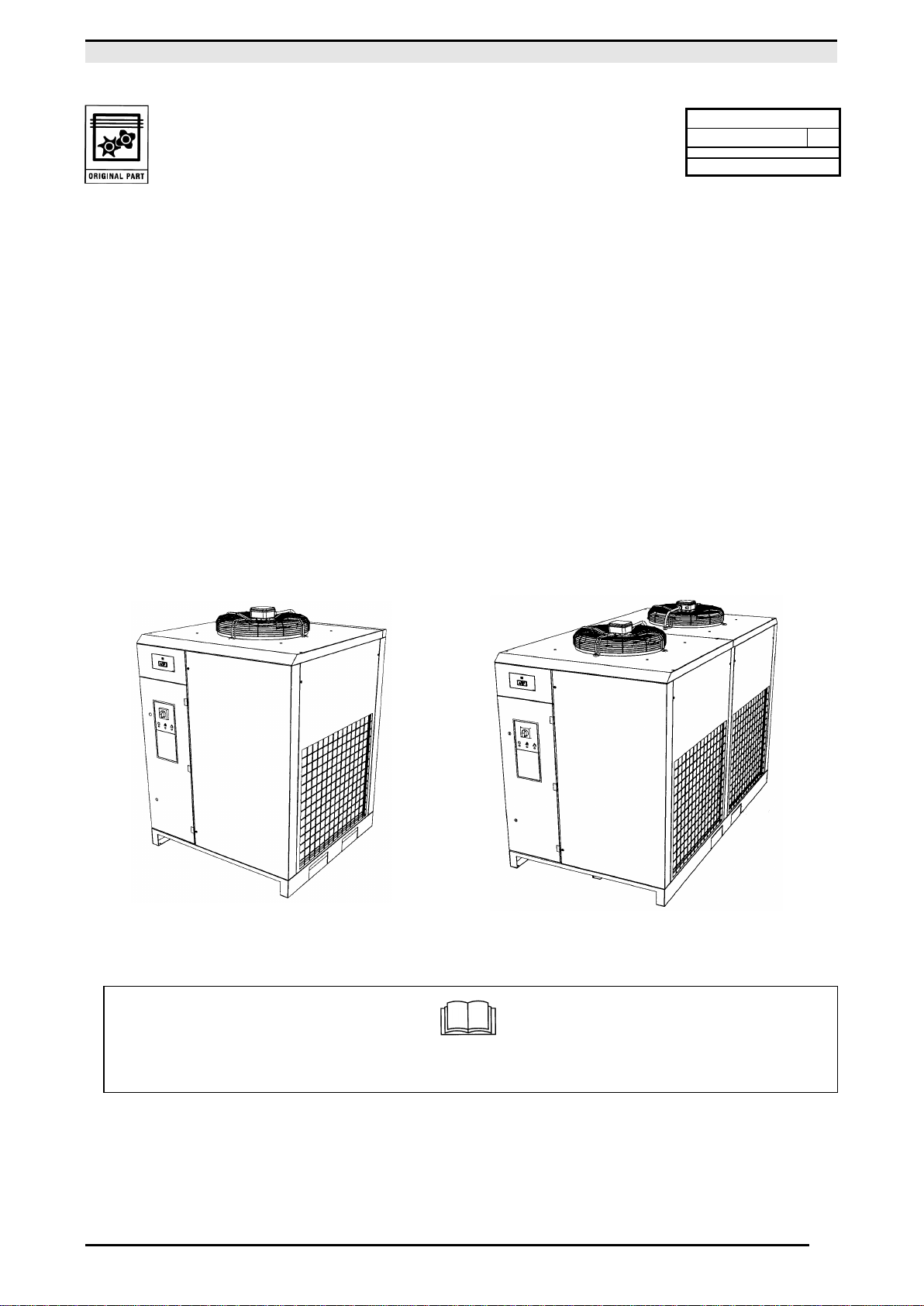
1.0 GENERAL CHARACTERISTICS
The dryer is a chilling machine with direct expansion and dry evaporator.
The air to be dried is sent to the heat exchanger in which the water vapour present is condensed: the condensate
gathers in the separator and is discharged outside through a steam trap.
2.0 INTENDED USE
The dryer has been built to dry the compressed air for industrial use. The dryer cannot be used in premises where there
is a risk of fire or explosion or where work is carried out which releases substances into the environment which are
dangerous with regard to safety (for example: solvents, inflammable vapours, alcohol, etc.).
In particular the appliance cannot be used to produce air to be breathed by humans or used on direct contact with
foodstuffs. These uses are allowed if the compressed air produced is filtered by means of a suitable filtering system
(Consult the manufacturer for these special uses.)
This appliance must be used only for the purpose for which it was specifically designed. All other uses are to be
considered incorrect and therefore unreasonable. The Manufacturer cannot be held responsible for any damage resulting
from improper, incorrect or unreasonable use.
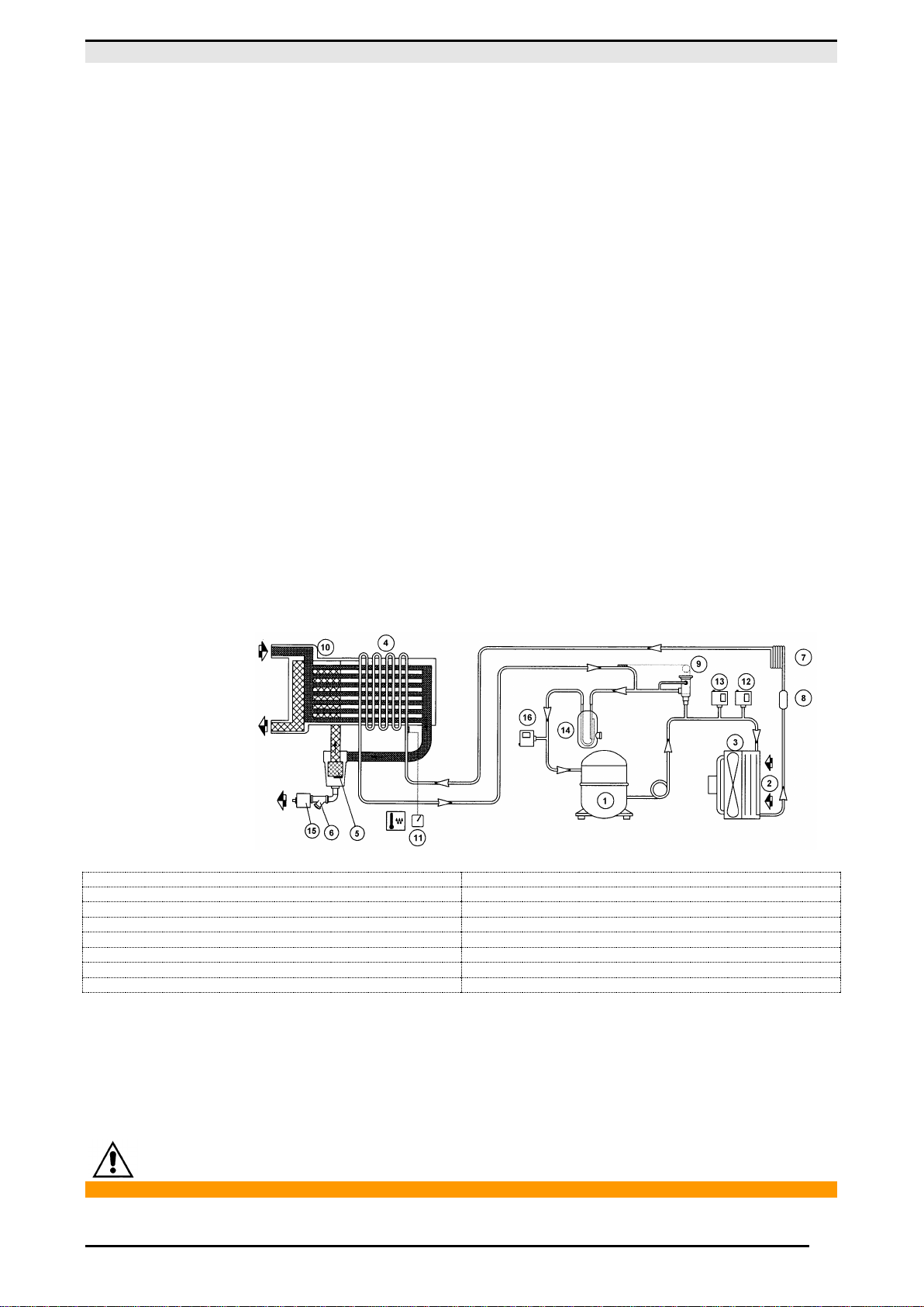
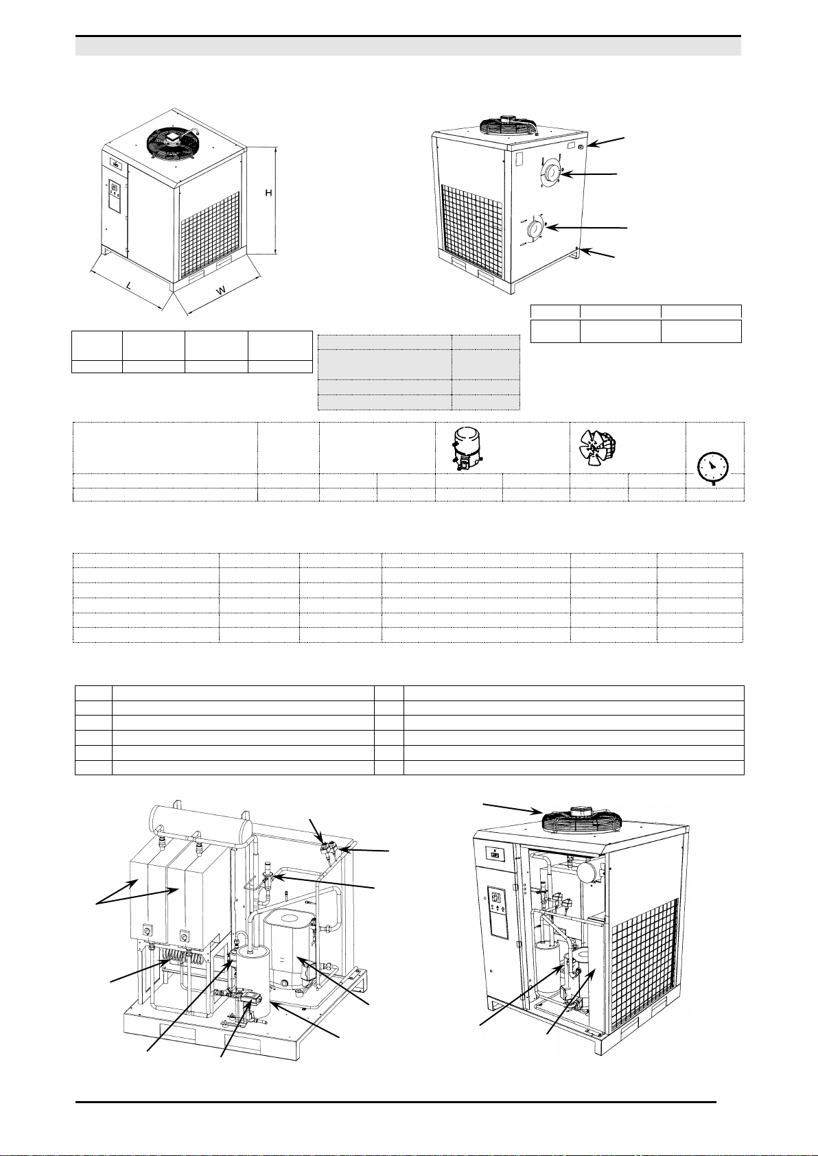
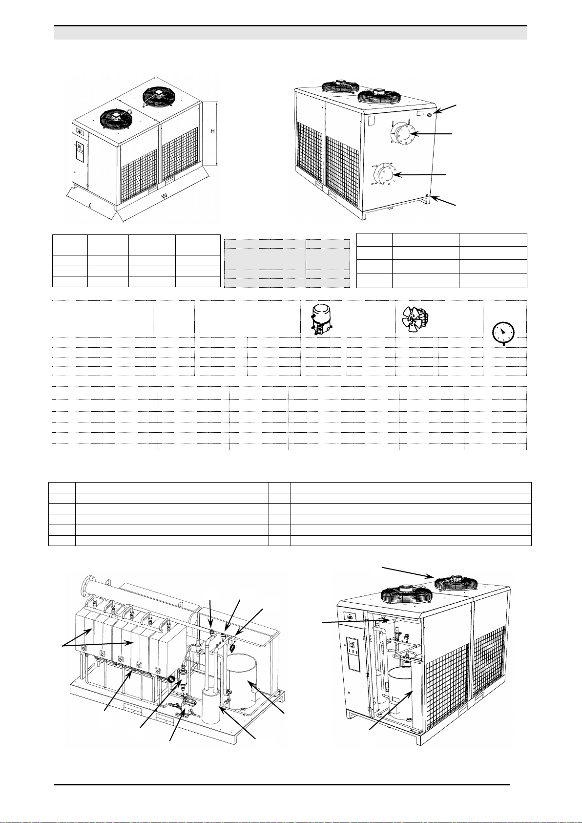
3.0 OPERATION
The gaseous refrigerant coming from the evaporator (4) is sucked by the refrigeration compressor (1) and it is pumped
into the condenser (2). This one allows its condensation, eventually with the help of the fan (3); the condensed refrigerant
passes through the dewatering filter (8) and it expands through the capillary tube (7) and goes back to the evaporator
where it produces the refrigerating effect.Due to the heat exchange with the compressed air which passes through the
evaporator against the stream, the refrigerant evaporates and goes back to the compressor for a new cycle.
The circuit is equipped with a bypass system for the refrigerant; this intervenes to adjust the available refrigerating
capacity to the actual cooling load. This is achieved by injecting hot gas under the control of the valve (9): this valve
keeps constant the pressure of the refrigerant in the evaporator and therefore also the dew point never decreases below
(0 °C / 32 °F) in order to prevent the condensate from freezing inside the evaporator. The drier runs completely
automatically; it is calibrated in the factory for a dew point of 3 °C (37,4 °F) and therefore no further calibrations are
required.
DRYER FLOW DIAGRAM
1) REFRIGERANT COMPRESSOR
12) FAN CONTROL PRESSURE SWITCH
5) DEMISTER CONDENSATE SEPARATOR
7) EXPANSION CAPILLARY TUBE
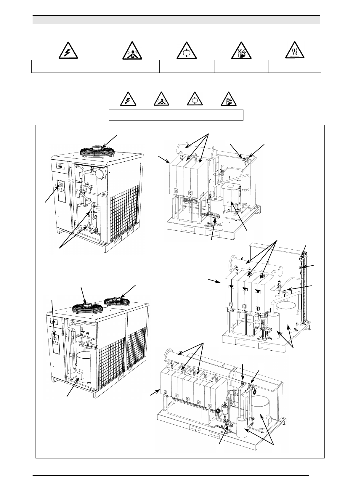
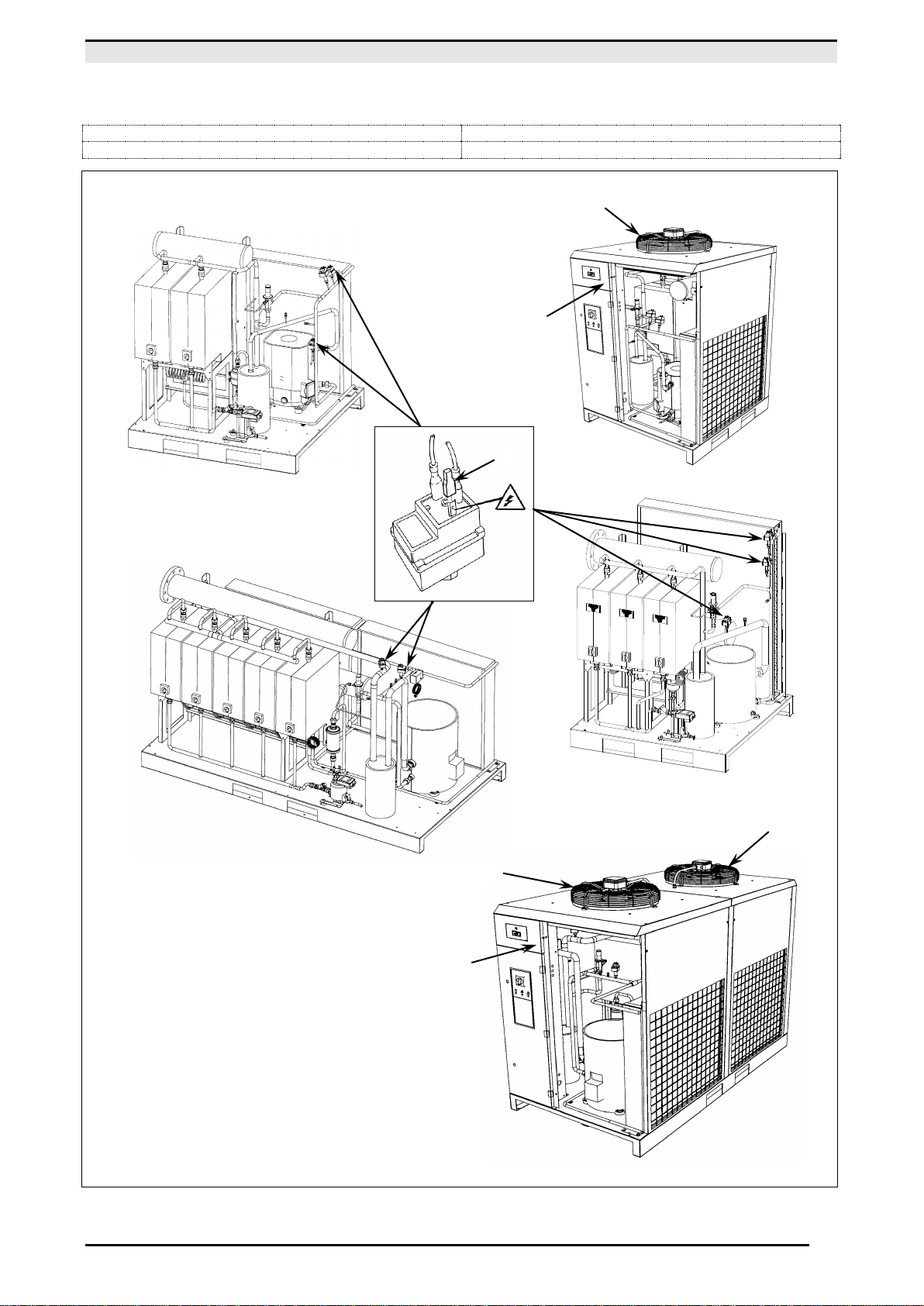
4.0 GENERAL SAFETY STANDARD
The appliance may be used only by specially trained and authorized personnel.
Any tampering with the machine or alterations not approved beforehand by the Manufacturer relieve the latter of
responsibility for any damage resulting from the above actions.
The removal of or tampering with the safety devices constitutes a violation of the European Standards on safety.
ALL WORK ON THE ELECTRIC PLANT, HOWEVER SLIGHT, MUST BE CARRIED OUT BY PROFESSIONALLY SKILLED PERSONNEL.