Quincy EQ LTE 2014900479 User manual

Equipment Technical Manual
Base Station

Complete Kit & Additional Loggers
EQ LTE Recommended Kit
2014900479
EQ LTE, Logger, Current & Volts (CS800) (10-800Amps)
EQ LTE, Logger, pressure, 0-16 BAR (0-232 psi)
EQ LTE, Base Station & Power Supply
Logger carry bag, Blue
2014900356
2014900357
2014900359
2014900360
EQ LTE, Base station & Power Supply
2014900359
2014900359 Kit Contains
EQ LTE, Base station
EQ LTE, Power Supply (100 - 240vAC input / DC output power supply c/w plug assortment)
Note: No case is supplied with this kit, items are supplied loose.
EQ LTE, Logger, Pressure (0 - 16BAR) - complete case kit
2014900357
2014900357 Kit contains
Logger Case
EQ LTE, Logger, pressure (0 - 16BAR) - logger & sensor assembly
EQ LTE, Logger, pressure (0 - 16BAR) - NPT adapter
EQ LTE, Logger, Current & Volts - complete case set
2014900356
2014900356 Kit contains
Logger Case
EQ LTE, Logger, current & volts - logger & current sensor assembly
Note: All battery powered loggers are supplied with batteries included.

Additional Loggers
EQ LTE, Logger, Flow - complete case kit
2014900361
2014900361 Kit Contains
Logger Case
EQ LTE, Logger, flow - logger assembly
EQ LTE, Sensor, flow
EQ LTE, Power Supply (100 - 240vAC input / DC output power supply c/w plug assortment)
EQ LTE, Logger, Temperature - complete case kit
2014900365
2014900365 Kit Contains
Logger Case
EQ LTE, Logger, temperature - logger & sensor assembly
EQ LTE, Logger, Moisture (dewpoint) - complete case kit
2014900362
2014900362 Kit Contains
Logger Case
EQ LTE, Logger, Moisture (dewpoint) - Logger assembly
EQ LTE, Sensor, moisture (dewpoint)
EQ LTE, Sensor, moisture (dewpoint) mounting chamber
EQ LTE, Power Supply (100 - 240vAC input / DC output power supply c/w plug assortment)
EQ LTE, Logger, 4 - 20mA - complete case kit
201400363
2014900363 Kit Contains
Logger Case
EQ LTE, Logger, 4 - 20 mA - logger assembly
EQ LTE, Logger, 4 - 20 mA - counter connector
EQ LTE, Power Supply (100 - 240vAC input / DC output power supply c/w plug assortment)
EQ LTE, Logger, 0-60bar. case kit
2014900358
2014900358 Kit Contains
EQ LTE, Logger, Case - flow - case only
EQ LTE, Logger, 0-60bar-log. & sensor
EQ LTE, Power Supply (100 - 240vAC input / DC output power supply c/w plug assortment)
Note: All battery powered loggers are supplied with batteries included.

Contents:
1.0
Safety Warning
1.1
SafetyWarning
1.2
Installation
1.3
Operation
1.4
Maintenance
1.5
Batteries
2.0 General description
3.0 Version revision
4.0
EQ LTE equipment
4.1
EQ LTE base station
4.1.1
Physical
4.1.2
Preparing for first use
4.1.3
General operation
4.1.4
Technical data
4.1.5
Power supply
4.1.6
Keypad
4.1.7
Graphical user interface
4.1.8
Menu navigation
4.1.9
E learning
4.2
EQ LTE data loggers
4.2.1
EQ LTE assemblycase
4.2.2
Physical
4.2.3
Preparing for first use
4.2.4
General operation
4.2.5
Power supply
4.2.6
Logger battery compartment
4.2.7
Keypad
4.2.7.1
Bluetooth key and LED
4.2.7.2
Diagnostic key and LED
4.2.8
Data logger installation
4.2.9
EQ LTE current and volt data logger
4.2.9.1
Technical data
4.2.9.2
Sensor installation
4.2.10
EQ LTE pressure data logger
4.2.10.1
Technical data
4.2.10.2
Sensor installation
4.2.11
EQ LTE temperature data logger
4.2.11.1
Technical data
4.2.11.2
Sensor installation
4.2.12
EQ LTE moisture data logger
4.2.12.1
Technical data
4.2.12.2
Sensor installation
4.2.13
EQ LTE flow data logger
4.2.13.1
Technical data
4.2.13.2
Sensor installation
4.2.14
EQ LTE 4 – 20mA datalogger
4.2.14.1
Technical data

Limit of Liability
The publisher and the author make no
representation or warranties with respect to the
accuracy or completeness of the contents of this
work and specifically disclaim all warranties,
including without limitation warranties of fitness for a
particular purpose. No warranty may be created or
extended by sales or promotional materials.
Neither the publisher nor the author shall be liable
for damages arising here from. The fact that an
organization or website is referred to in this work as
a citation and/or a potential source of further
information does not mean that the author or the
publisher endorses the information the organization
or website may provide or recommendations it may
make. Further, readers should be aware that
internet websites listed in this work may have
changed or disappeared between when this work
was written and when it is read.
Trademarks:
EQ LTE™, the EQ LTE logo are trademarks
or registered trademarks of Quincy
Compressor.
All other trademarks are the property of their
respective owners.
Copyright © Quincy Compressor. All rights reserved.
Page 2

SOFTWARE LICENSE AGREEMENT
PLEASE READ THIS SOFTWARE LICENSE
AGREEMENT CAREFULLY BEFORE USING THE
EQUIPMENT THAT CONTAINS THIS PRODUCT, YOU
ARE CONSENTING TO BE BOUND BY THIS
AGREEMENT.
IF YOU DO NOT AGREE TO ALL OF THE TERMS OF
THIS AGREEMENT, RETURN THE PRODUCT TO THE
PLACE OF PURCHASE.
Quincy Compressor and its suppliers grant to Customer
("Customer") a nonexclusive and non- transferable single
user license to use the Quincy Compressor software
("Software") in object code form solely on a single EQ LTE
product.
EXCEPT AS EXPRESSLY AUTHORIZED ABOVE,
CUSTOMER SHALL NOT: COPY, IN WHOLE OR IN
PART, SOFTWARE OR DOCUMENTATION; MODIFY
THE SOFTWARE; REVERSE COMPILE OR REVERSE
ASSEMBLE ALL OR ANY PORTION OF THE
SOFTWARE; OR RENT, LEASE, DISTRIBUTE, SELL,
OR CREATE DERIVATIVE WORKS OF THE
SOFTWARE.
Customer agrees that aspects of the licensed materials,
including the specific design and structure of individual
programs, constitute trade secrets and/or copyrighted
material of Quincy Compressor. Customer agrees not to
disclose, provide, or otherwise make available such trade
secrets or copyrighted material in any form to any third
party without the prior written consent of Quincy
Compressor. Customer agrees to implement reasonable
security measures to protect such trade secrets and
copyrighted material. Title to Software and documentation
shall remain solely with Quincy Compressor.
DISCLAIMER
EXCEPT AS SPECIFIED IN THIS WARRANTY, ALL
EXPRESS OR IMPLIED CONDITIONS,
REPRESENTATIONS, AND WARRANTIES INCLUDING,
WITHOUT LIMITATION, ANY IMPLIED WARRANTY OF
MERCHANTABILITY, FITNESS FOR A PARTICULAR
PURPOSE, NONINFRINGEMENT OR ARISING FROM A
COURSE OF DEALING, USAGE, OR TRADE
PRACTICE, ARE HEREBY EXCLUDED TO THE
EXTENT ALLOWED BY APPLICABLE LAW.
IN NO EVENT WILL Quincy Compressor OR ITS
SUPPLIERS BE LIABLE FOR ANY LOST REVENUE,
PROFIT, OR DATA, OR
Page 3

Page 4
Section 1: Safety Warning:
Section 1.1: Safety warning
This ‘EQ LTE product wide’ safety warning
should be read and understood. Additional
safety information is contained in this manual.
Both the EQ LTE product wide and additional
safety information contained in the manual
must be read and understood.
Warning: Risk of danger
Warning: Risk of electric shock
Warning: Risk of high pressure
Warning: Risk of burn
Warning: Risk of fire
Warning: Consult manual
Do not install or operate the EQ LTE™
product(s) (hereinafter can be referred to as
the device) until you and all personnel
concerned have read and established a
working understanding of the device inclusive
of duties to be performed while installing,
operating and maintaining the device.
This manual contains IMPORTANT SAFETY
DATA and should be printed and kept with the
device at all times.
Improper use of the device may compromise
the safety and protection of the device and its
environment.
Never use the device in explosive
environments.
Use only CATIII 600V or better insulated, test
leads and voltage probes as supplied with the
device.
Before use, verify current clamp, test leads
and voltage probes for damage or wear
indicators, dispose of and replace when
damaged or worn.
No serviceable parts inside, disposeaccording
to local regulations.
Wall adaptor is part of a SELV circuit, useonly
supplied net adapter.
Don’t mix lead and voltage probe colors and
disconnect unused leads to prevent short
circuits.
Do not expose this device to heat, fire ordirect
sunlight.
When installing, commissioning, operating or
carrying out service or maintenance on the
device, personnel must use relevant safe
working practice and observe all relevant local
health and safety requirements and
regulations.
Lethal voltages may be present at or around
the device. Electricity has the potential to
cause severe personal injury or death. Use
extreme caution when carrying out checks
where lethal voltages may exist.
Never remove or tamper with safety devices,
guards or insulation materials fitted to the
device or the compressed air installation.
Compressed air has the potential to cause
severe personal injury or death. Use extreme
caution when carrying out compressed air
related checks.
Hot and cold surfaces may be present at or
around the device. Use caution as necessary
A requirement of fault-free operation and
fulfilment of any right to claim under guarantee
is that documentation is observed.
This document is subject to change without
notice, if in doubt, do not proceed!
It is not possible to anticipate every
circumstance that might represent a potential
hazard. If the operator employs an operating
procedure, an item of equipment or a method
of working which is not specifically
recommended the user must ensure the
product will not be damaged or made unsafe
and that there is no risk to persons or property.
Failure to observe safety precautions or
implement safe working practices may be
considered dangerous practice or misuse of
the device.
Section 1.2: Installation
Installation work must only be carried out by a
competent person under qualified supervision
equipped with the correct tools and
appropriate protection against hazards.
When necessary, locate the emergency power
off before installing the device; never work
alone if potentially hazardous conditions exist.
Disconnect the power before connecting the
device, never assume power is off but always

Page 5
check the circuit. Be aware that other nearby
circuits can still be powered.
Do not open access panels or approach
electrical components while voltage is applied
unless measurements are impossible
otherwise. When hazardous live parts are
exposed use personal protective equipment to
prevent risk of electric shock. Use suitable
protective gloves, fire resistant clothes and
face protection when working with live
conductors. Keep fingers behind protective
barriers.
The current and voltage logger is rated CAT III
and must always be connected behind the
installation’s circuit breakers.
Do not use the device in environments where
vibration or shocks are likely to disrupt the
function or compromise the safety of the
device.
Do not wear loose clothes or jewelry like
chains or bracelets which could make contact
with electrical components.
Allow the installation environment to cool or
heat to acceptable temperatures before
attempting to install a device sensor.
Always ensure any pressure within a
compressed air system is safely vented to
atmosphere before attempting to remove or
install a device sensor, never assume the
compressed air system is vented but always
check the air gauge. Be aware that other
nearby parts can still be hot, cold or
pressurized.
The device should be installed in such a
location as to allow operational and
maintenance access to the installation without
obstruction or hazard and to allow clear
visibility of indicators at all times.
Section 1.3: Operation
Correct operation of the device may only be
checked by trained personnel according to
safe practices equipped with appropriate
protection against hazards.
The device must only be operated at the
ratings: supply voltage, frequency, pressure,
temperature, altitude, humidity and
environmental rating for which it is designed.
Do not operate the device without battery
door, enclosure open or covers removed.
The device’s batteries are monitored,
replacing the batteries during operation is not
necessary.
Do not operate the device in high humidity
environments or with wet hands
Do not direct access panels or
expose electrical components while
device is operating.
Section 1.4: Maintenance
Maintenance must only be carried out by
competent personnel under qualified
supervision.
If replacement parts are required use only
genuine parts from the original equipment
manufacturer.
Before competent personnel under qualified
supervision remove any access panels or
carry out work on the device, isolate from the
source of supply power using relevant and
local safe isolation procedures.
Ensure that all instructions concerning
operation and maintenance are strictly
followed and that the complete device, with all
accessories and safety devices, is kept in
good working order.
The accuracy of sensor devices must be
checked on a regular basis. They must be
renewed when acceptable tolerances are
exceeded. Always ensure any pressure within
a compressed air system is safely vented to
atmosphere before attempting to remove or
install a sensor device.
The device must only be cleaned with a damp
cloth, using mild detergents if necessary.
Avoid the use of any substances containing
corrosive acids or alkalis. Remove all input
signals before cleaning the device.
Do not paint the control facia or obscure any
indications, controls, instructions or warnings
Section 1.5: Batteries
Do not use other types of batteries than those
originally supplied.
Use supplied batteries only in device as
intended. Pay attention on the polarity when
fitting batteries.
Keep batteries out of reach from children and

Page 6
animals. Get medical help in case a battery
has been swallowed.
When replacement batteries are required,
replace all four batteries inside the device
battery compartment with suitable new ones.
Do not store batteries in environments with
loose metal parts or exposed to moisture,
heat, fire or direct sunlight.
Do no expose batteries to vibration, impactsor
deformation.
Fire, explosion and sever burn hazard. Do not
recharge, crush, disassemble, heat above
100°C, incinerate batteries or expose contents
to water.
Consult IATI guidelines describing safe air
transport of Li-ion batteries.
Dispose of batteries according to local
regulations. A recycle program might be
applicable.
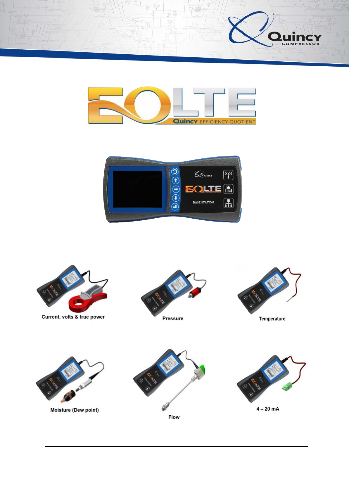
Section 2: General description
EQ LTE™… Compressed air analytics made
easy!
Advanced hardware, software and cloud
computing solutions that enable compressed
air and vacuum systems to be quickly and
easily audited.
EQ LTE™ offers market-leading, innovative
and technically advanced solutions that
streamline traditional compressed air system
audits.
Seamlessly integrating robust hardware and
software platforms… The success of EQ
LTE™ has been built upon a unique ability to
seamlesslyintegrateour ownrobustprocessor
and input/output hardware platforms with a
comprehensive software library to provide a
bespoke compressed air and vacuum auditing
solution.
Streamlining data collection, improving
analysis… First, our EQ LTE™ data loggers
incorporate high quality sensors to collect and
store information relating to a system’s
pressure,temperature, moisture dewpoint and
flow rate. In addition, our current and voltage
loggers enable true power tobe accurately
calculated.
The very latest Bluetooth technology then
enables this information to be effortlessly
transferred from multiple data loggers to a
single, intelligent EQ LTE™ base station. In
turn, the base station transfers this data to our
quincy.scadar.net cloud computing platform.
Here, it is encrypted and stored so that is can
be securely accessed and interrogated by
users 24 hours a day.
Combining unique application expertise with
proven hardware and software platforms to
deliver the complete, value-adding analytics
service… EQ LTE™ provides customers with
the reassurance of working with an
experienced, market-leading partner
positioned at the very forefront of technology.
Evaluating requirements… Whilst developing
EQ LTE™, we took time to carefully evaluate
traditional compressed air auditing
procedures. Once these were clearly
understood, our analytics specialists began to
formulate a solution that made things simpler.
PLC hardware engineering… Our partners
are vastly experienced in the development of
processor and input/output hardware
platforms. This expertise has enabled us to
manufacture a range of EQ LTE™ data
loggers that feature 16 bit precision sensor
inputs with the capacityto store more than 1.4
million data samples.
Powered by 110-240v AC mains or batteries
that can offer an incredible working life of two
years or more, our data loggers record
information on pressures up to 60 bar (870
psi), temperatures from -50°C - +200°C
(-58°F - +392°F), moisture dew point from -
80°C - +20°C (-112°F to +68°F), flow rates to
185m/sec (607 ft/sec) and current and voltage
from 10 – 800Amp and 100 V – 700V
respectively. Additionally, there’s a 4-20mA
data logger that can be used with a variety of
sensor types.
EQ LTE™ base stations are also robustly
constructed and incorporate a 3.5” VGA color
display and ergonomically designed keypad.
PLC software development

Page 7
3.0 Version revisions
Use the base station graphical user interface
and EQ LTE™ base station operating
procedures to maintain software in both the
EQ LTE™ base station and EQ LTE™ data
loggers.
Audit configuration and logger data are
unaffected by the software update process.
As such, a base station software update can
be performed at any time.
Updating of loggers should not be performed
whilst the data logger is in operation (i.e.
installed and logging data). Complete any
logging activity and transfer any logged data
from data loggers to base station and to the
cloud computing environment before
performing a data logger software update
4.0
EQ LTE™ equipment
4.1
EQ LTE™ base station
4.1.1
Physical
Front elevation
Back elevation
Side elevation
Side elevation
Note:
A tamper resistant label providing device ID,
serial number and original equipment
manufacturer bar code data is located on the
back elevation of the base station
4.1.2
Preparing for first use
Each EQ LTE™ base station is supplied with a
power supply and a variety of ‘domestic’power
supply heads.
You will also require an Ethernet CAT 5e cable
(not supplied), an accessible CAT 5e RJ45
socket, and an IP address with access to the
World Wide Web and a source of supply power
for the EQ LTE™ base station.
First, select the appropriate ‘domestic’ power
supply head and complete assembly of the
power supply. Insert the power supply jack
into the socket of the EQ LTE™ base station
and apply supply power. Following a device
boot sequence, the graphical user interface
will display.
Connect an Ethernet CAT 5e cable (not
supplied) to the RJ45 socket of the EQ
LTE™ base station and to an accessible
RJ45 socket with access to the World Wide
Web.
Establish an IP address for the EQ LTE™
base station using either DHCP ormanual
input methods (see notes below).

Page 8
Finally, and only after an internet connection
has been established; perform a base station
update as described in this manual.
Your EQ LTE™ base station is ready for use!
Notes: EQ LTE™ base stations use
conventional DHCP or manual IP
configuration methods.
The manufacturers do not provide
support relating to the use of
ancillary products such as WIFI
dongles.
Network security restrictions may
prevent the EQ LTE™ base station
from accessing the internet
If you experience internet connection
difficulties, contact your local IT
administrator in the first instance!
4.1.3
General operation
A EQ LTE™ base station provides users with a
‘PC free’ solution for the handling of data
between the quincy.scadar.net cloud
computing environment and EQ LTE™ data
loggers
The EQ LTE™ base station allows users to
download audit configurations from the
quincy.scadar.net cloud computing
environment, wirelessly synchronize audit
configurations with up to 20 EQ LTE™ data
loggers, wirelessly retrieve logged data from
up to 20 EQ LTE™ data loggers and return
logged data to the quincy.scadar.net cloud
computing environment.
Once audit configurations are synchronized,
EQ LTE™ data loggers can log datawithout
the need for any further connection with the
EQ LTE™ base station.
Although identical in size and rugged in
design, the EQ LTE™ base station is not
intended to accompany data loggers to the
audit location. More typically, the
EQ LTE™ base station will remain connected
to an office local area network with internet
access and act as an instantly accessible
portal for the transfer of data between the
quincy.scadar.net cloud computing
environment and EQ LTE™ data loggers.
Once EQ LTE™ data loggers return from
the audit location, simply synchronize with the
EQ LTE™ base station once more and
transfer your logged data from the EQ LTE™
base station to the quincy.scadar.net cloud
computing environment.
Only one EQ LTE™ base station is required to
manage data between the quincy.scadar.net
cloud computing environment and an infinite
number of EQ LTE™ data loggers.
4.1.4
Technical data
Function:
Handles data between EQ LTE™
data loggers and the quincy.scadar.net
cloud computing environment
2014900359
IP20
(W x H x D): 98 x 203.2 x 34.8mm
(0.32 x 0.66 x 0.11 ft)
0.31 kg (11 ounces)
Ethernet:CAT5e 10/100Mbps
RJ45
LED A: flashes to indicate
communications
LED B: On when 100Mbps connection
is detected
Off when 10Mbps is active
USB type B (not used)
Input power: 100 – 240V AC
50 – 60Hz
0.6 A
Supplied with EU, UK & US AC heads
as standard
Output power: 24vDC
0.75Amp
1.8M (5 foot) jack lead
3.5” color ¼VGA
Part Number
IP rating:
Dimensions:
Weight:
Connection:
USB:
Power:
Graphic display:
Keypad: 5 tactile key, membrane switch panel
construction
Bluetooth:
V2.1 + EDR (enhanced data rate)
master device with capacity to
simultaneously communicate with up to
20 slave data loggers
Bluetooth
range:
10 meters (33 ft)
The effective range varies due to propagation conditions,
material coverage, production sample variations, antenna
configurations and battery conditions
Software
Pre programmed application software
configurable via OUI
Languages:
N/A
Display
symbols:
ISO7000 and custom
Approvals:
CE, FCC
Operating temp:
0°C ~ +40°C (+32°F ~ +104°F)
Storage temp:
-25°C ~ +70°C (-13°F ~ +158°F)
Relative
humidity:
<95% condensation @ 40°C (104°F)
without condensation
4.1.5
Power supply
The EQ LTE™ Base Station is powered
from an external power supply which can be
operated from a regular ‘domestic’ power
supply.
Operating voltage:
90 - 264 Vac

Page 9
Frequency range:
47- 63Hz
4.1.6
Keypad
Use BACK, UP, DOWN, RIGHT, and ENTER
keys as appropriate
4.1.7
Graphical user interface
The graphical user interface of the
EQ LTE™ base station is designed to
complement the quincy.scadar.net
cloud computing environment.
The graphical user interface uses animated
images and simple text to articulate device
state or condition. Common menus are
described in this manual.
4.1.8
Menu navigation
Cloud to base: Used to
collect Audit Wizard
configuration files fromthe
quincy.scadar.net cloud
computing environment
Cloud to base: Collecting
Audit Wizard configuration
files from
quincy.scadar.net
Base to logger(s): Used to
transfer Audit Wizard
configuration files from
base station to logger(s)
using Bluetooth
Base to logger(s):
Distributing logger
configuration files to
loggers.
Logger(s) to base: Used to
transfer data files from
logger(s) to base station
using Bluetooth
Logger(s) to base:
Returning logger data to
base station
Base to cloud: Used to
transfer data files from
base station to the
quincy.scadar.net cloud
computing environment
Settings: Used to configure
base station IP, set time
and date, update base
station and / or logger
device software
Settings/IP: Used to access
base station IP
configuration menu
Settings/IP: Used to
configure for DHCP or set
IP address manually
Settings/Update base
station: Used to download
base station software
updates from
quincy.scadar.net
Settings/Update base
station: Existing and cloud
software version
confirmation with ‘update’
or ‘abort’ keys
BACK
UP
DOWN
RIGHT
ENTER

Page 10
Settings/Download logger
update: Used to download
logger software updates
from quincy.scadar.net. to
logger(s) using Bluetooth
Settings/Update loggers:
Used to initiate update of
logger(s) via Bluetooth
Settings/Update loggers:
Screen prompt indicating
that operator should press
the logger(s) Bluetooth
button
Settings/Time and Date:
Used to set time, date and
date formats
Base station ID: Use to
establish the Base station
ID number as well as
current operating software
version
Note: Case contents vary.
Each case features:
•
Durable polypropylene material
•
Raised feet and a straight hinge for
stability when upright
•
Carryhandle
•
Two shaped and robust locks either
side of carryhandle
•
Transportation feet for stability when
stacked
•
Formed cushion insert
•
Tamper resistant label providing
device ID, serial number and original
equipment manufacturer bar code
data for easy identification (Do not
remove)
4.2.2 Physical
4.1.9 E learning
This technical manual is not intended to be a
source of learning for the EQ LTE™ user
interface. Instead, detailed work and user
instructions explaining use and operation of
the software can be found one the homepage
of quincy.scadar.net.
4.2 EQ LTE™ data loggers
4.2.1 EQ LTE™ assembly case
Each EQ LTE™ data logger is supplied in a
custom manufactured polypropylene case with
cushion insert. The case and cushion insert is
designed to protect your investment as well as
provide for a flexible yet safe storage and
transportation system.
The
Front elevation
Rear elevation

Page 11
Side elevation
Side elevation
4.2.3
Preparing for first use
Using a EQ LTE™ base station; check the
installed data logger software version with the
software version available online and perform
a data logger update as necessary.
Your EQ LTE™ data logger is ready for first
use!
4.2.4
General operation:
Each EQ LTE™ data logger is equipped witha
sensor which is permanently connected to the
data logger, except the current and volt
logger which features detachable voltage
alligator clips and test leads and the 4-20mA
data logger which is intended for use with any
sensor (not supplied) that features a suitable
4-20mA output signal.
All data loggers provide sufficient memory to
store audit data for a minimum of 14 days and
at a fixed resolution of 1 sample per second.
To protect audit data, data loggers feature
batteries with lifetime estimated at two
calendar years or more. To further improve
ease of use, the EQ LTE™ base station will
alert the operator and prevent a logger
configuration from taking place if battery
condition would prevent the data log from
completion.
4.2.5
Power supply
All EQ LTE™ data Loggers are powered
using internal lithium batteries.
Some EQ LTE™ data loggers also feature an
external power supply input. This is used to
power the data logger sensor.
Note: The use of an external power supply
unit does not eliminate the use of or
need for the data logger’s internal
lithium batteries!
When featured, the EQ LTE™ data logger
sensor is powered via the EQ LTE™ data
logger power supply jack. This can be
operated from a ‘regular’ domestic power
supply. Select the appropriate ‘domestic’
power supplyhead and complete assemblyof
the power supply. Insert the power supply
jack into the socket of the EQ LTE™ data
logger and apply supplypower.
Notes: It is not necessary toexternally
power the EQ LTE™ data logger
whilst transferring data to and from
the data logger and a EQ LTE™
base station
When in use, verify that power
supplies are plugged in and working
as intended using the data logger
LED diagnostic feature
Ensure that the wall socket power
connection will not be disturbed,
knocked or otherwise disrupted
whilst data is being logged
4.2.6
Logger batterycompartment
The data logger battery compartment can be
found on the rear elevation of the data logger.
Use an appropriately sized crosshead
Note:
Do not remove the tamper resistant label
providing device ID, serial number and original
equipment manufacturer bar code data is located
on the rear elevation of the data logger
Operating voltage:
90 - 264 Vac
Frequency range:
47- 63 Hz

Page 12
screwdriver to unscrew and access the battery
compartment by removing the battery
compartment door.
When required to do so, change all batteries!
Take care to observe battery polarity when
inserting new batteries into the battery
compartment.
With the data loggers back
elevation facing you and the
logger orientated upright (when
the tamper resistant data logger
serial number and bar code are
above the battery compartment
door) batteries are inserted as
follows…
4.2.7.2 Diagnostic key & LED
Press the diagnostic key as necessary…
Key location: Front elevation, bottom right
Key symbol:
ONLY USE BATTERIES
RECOMMENDED IN THIS
MANUAL FLASHING SOLID ON
Key function: Logger diagnostics
LED color: Red
LED
diagnostics:
BATTERY COMPARTMENT LID
SCREW RETAINING THREAD
BATTERY GRIP
BATTERY GRIP
BATTERY COMPARTMENT LID
SCREW RETAINING THREAD
OFF
Low batteries
Troubleshooting: Check battery condition
and replace batteries as necessary
Slow flash
Not configured
Troubleshooting: Create audit
configuration, transfer from cloud to base
station and then from base station to
logger
Fast flash
Configured,
not sensing
data
Troubleshooting: Check installation
Fast flash
All data
loggers
except
current and
volt logger…
Configured,
sensing valid
data
Fast flash
Current and
volt logger
only…
Configured,
sensing
current data,
not sensing
valid voltage
data
Troubleshooting: Check installation
Current and
volt logger
only…
4.2.7 Keypad
EQ LTE™ data loggers feature two keys on
the device front elevation identified by a key
symbol. Each key feature an associated LED
located directly above the key / symbol.
4.2.7.1 Bluetooth key & LED
When prompted by a base station to do so,
press the Bluetooth key…
Key location: Front elevation, bottom left
Key symbol:
FLASHING
Key function: Bluetooth operation
LED color: Blue
LED OFF
diagnostics:
SOLID ON
Not paired
Searching for
base station
Slow flash
Fast flash (50ms on / 50ms off)
Pairing or
Transferring
data
ON
Paired
Time out:
1 minute
If a data logger has not found a
discoverable base station within one
minute, the search will end.
Try again

Page 13
Fast flash
Configured,
sensing
current data,
sensing
voltage data
Fast flash
Current and
volt logger
only…
Configured,
not sensing
valid data
Troubleshooting: Check installation
Time out: 5 minutes
LED diagnostics will remain ON for 5
minutes after the key is pressed
4.2.8
Data logger installation
Prior to installation make sure that data
loggers are configured using the Audit Wizard
feature at quincy.scadar.net.
Print and retain the audit configuration check
list before attending the audit location!
Download the audit configuration from
quincy.scadar.net to your EQ LTE™ base
station
Transfer the audit configuration from your EQ
LTE™ base station to each EQ LTE™ data
logger
Ensure that each data logger is installed to the
assigned audit location (e.g. air compressor
brand, model and or serial number or pressure
point)
4.2.9
EQ LTE™ current & volt data logger
4.2.9.1
Technical data:
Identification:
EQ LTE™ Logger, current & volts
2014900356
EQ LTE™
EQ LTE™ current & volts
data logger
Precision data logging
Part number:
Product family:
Definition:
Function:
Data logger:
A / D resolution:
16 bit
Battery life:
2 calendar years or more
(est.)
Bluetooth (slave):
2.1 + EDR (enhanced data
rate)
Bluetooth range:
10 meters (33 feet)
The effective range varies due to propagation
conditions, material coverage, production
sample variations, antenna configurations and
battery conditions
Operating temp:
0°C ~ +55°C (+32°F ~
+131°F)
Power / batteries:
Four AA lithium primary cells,
Li/SOCI2, 3.6V, 2700mAh
Real time clock:
Precision real time clock
(temp compensated crystal)
Maximum deviation:
0.4s / day
Sample capacity:
More than 1.4 million samples
(16 days continuous logging)
Sample frequency:
1 second (fixed resolution)
Software:
Pre-programmed application
software
Current sensor:
AC voltage: Range: 100 V to 700 V
Accuracy: 1%
AC current:
Range: 10 Amp ~ 800Amp
Accuracy:
1%
Max nondestructive
current:
2000 A
Ambient temperature
influence on accuracy:
<0.1% per 1°C for
temperatures from -10°C to
+18°C and from 28°C to 50°C
Rise / fall time:
< 400ms
Burden resistance:
≤1 ohm
Operating temp:
-10°C ~ +50°C (+14°F ~
+122°F)
Storage temp:
-40°C to +70°C (-40°F to
+160°F)
Safety rating:
CAT III 600V
Useable frequency:
10Hz – 100 kHz
Dimensions:
216mm (8.5”) x 111mm (4.4”)
x 45mm (1.8”)
Jaw capacity:
52mm (2.05 inch)
Weight
0.65kg (1.4lb)
Conformity:
Drop test:
Mech and shock test:
IEC61010-031: 2008
IEC61010-1: 2010
IEC 68-2-32 @ 1 meter
IEC 68-2-27 @ 100G
Regulatory mark:
CE, UL
Volt measurement and test lead set:
Measuring device: Alligator clip set (2)
Red & black pair of small,
insulated, nickel plate jaws
Blunt tip grabs round screw
heads up to 9.5mm
CAT IV 600V, CAT III 1000 V,
10A rating
Test lead set:
Red & black with safety
shrouded, standard diameter
banana plugs
Right angle connector on one
end and straight connector on
the other
Reinforced strain relief
1.5metre silicone-insulated
wire resists heat & cold
CAT IV 600V, CAT III 1000 V,
10A rating
Conformity:
EN 61010-1-032
73/23/EEC, Low voltage
(amended 93/68/EEC)
Regulatory mark
CE, UL

14
Page
4.2.9.2
Sensor installation
Warning risk of electrical shock, high
pressure and moving parts. Read and
understand all safety instructions for
both EQ LTE™ data logger and the
compressed air installation and their
risks where the data logger will be
used before proceeding.
If in doubt stop immediately!
Use the sensor (current clamp) only as
specified in this manual and on 50 or 60HzAC
power supply cables only or the protection
provided by the device can be compromised.
Do not connect the sensor (current clamp) to
DC power supply cables
Examine the case of the device sensor and
sensor accessories regularly. Look for cracks
or missing plastic. Carefully look at the
insulation around the connectors.
Make sure the battery door is closed and
secure before operating the device.
Remove the test leads from the device before
the battery door is opened.
When variable speed drives are a feature of
the air compressor being logged, place the
sensor (current clamp) on the input powerside
of the variable speed drive.
Do not attempt to close the jaws of the sensor
(current clamp) around a conductor carrying
more than 1000 Vac
Do not attempt to close the jaws of the sensor
(current clamp) around more than one of the
three phase power supply cables
Do not mount the sensor (current clamp) to a
compressor main motor cable, this will not
record the total compressor input current flow
and will give inaccurate results.
Do not use the device around explosive gas,
vapor or in wet environments.
Do not use the device if it operates incorrectly.
Protection can be compromised.
Examine the test leads for damaged insulation
or exposed metal. Check test lead continuity.
Replace damaged test leads before using the
device
Locate test leads appropriately. Safeguard
against test lead damage during installation
and throughout the audit duration.
Safeguard against test lead damage when
securing electrical cabinet doors.
The EQ LTE™ current and volt logger utilises
a split ferrite core type sensor current clamp.
De-energize the installation and place the
current clamp over a single conductor
supplying current to the entire air compressor
package as illustrated below.
Ensure the jaws of the current sensor are
securely closed around the cable to enable
data acquisition with accuracy.
Connect the RED alligator clip voltage
measurement device to the same phase that
the current sensor as illustrated below.
Connect the BLACK alligator clip voltage
measurement device to Earth as illustrated
below.
To protect the device, locate the alligator clips
after the electrical system fuses as illustrated
below.
Note: The use ofalternative volt
measuring devices tothe
alligator clip setprovided with
each EQ LTE™current and
volt data logger ispermissible.
Proceed with caution; check
compatibility of any alternative
volt measuring devices before
proceeding and observe safe
working practices!
Assembly:
External protection: Polypropylene case, molded
cushion insert
Size:
Logger (W x H x D)
98 x 203.2 x 34.8mm
3.8 x 8.0 x 1.3 inch
Sensor (W x H x D)
111 x 216 x 45mm
4.4 x 8.5 x 1.7 inch
Case (W x H x D)
437 x 379 x 100mm
17.2 x 14.9 x 3.9 inch
Weight:
2.67kg (5.8lbs)

Page 15
Note:
•
Where possible, we recommend that
installers use an accessible multi-
meter to verify the voltage reading.
When verifying the voltage reading
remember that the value measured
will equal the local 3 phase voltage /
1.732 (i.e. the square root of the 3-
phase system). For example, if you
have a 415V supply voltage, an
accurate voltage measurement at
the multi-meter will be between 239
and 240 volts (415 / 1.732 = 239.6).
EQ LTE™ data loggers correct this
measurement to reflect the actual 3
phase value!
Any voltage inconsistency is likely to be
associated with the earth bond. Be observant
of issues such as paint, dirt or other ingress
acting as a barrier between the BLACK volt
probe and the earth source!
4.2.10
EQ LTE™ pressure datalogger
4.2.10.1
Technical data
Identification:
EQ LTE™ Logger, pressure, 0
– 16 Bar
Or
EQ LTE™ Logger, pressure, 0
– 60 Bar
Part number:
0 – 16 BAR (0 – 232 psi)
2014900357
EQ LTE™
EQ LTE™ pressure data logger
Precision data logging
16 bit
2 calendar years or more
2.1 + EDR (enhanced data rate)
10 meters (33 feet)
The effective range varies due to propagation conditions,
material coverage, production sample variations, antenna
configurations and battery conditions
Product family:
Definition:
Function:
Logger:
A / D resolution:
Battery life:
Bluetooth slave:
Bluetooth range:
Operating temp:
0°C ~ +55°C (+32°F ~ +131°F)
Power:
Four AA lithium primary cells,
Li/SOCI2, 3.6V, 2700mAh batteries
Real time clock:
Precision real time clock
(temperature compensated crystal)
Maximum
deviation:
0.4s / day
Sample capacity:
More than 1.4 million samples
(16 days continuous logging)
Sample
frequency:
1 second (fixed resolution)
4.2.10.2
Sensor installation
Warning risk high pressure. Isolate
gas connection from the compressed
air system (e.g. gate or ball valve)
before attempting to locate the
pressure sensor. Read and
understand all safety instructions for
both EQ LTE™ data logger and the
compressed air installation and their
risks where the data logger will be
used before proceeding.
If in doubt stop immediately!
Locate the pressure sensor in such a way as
to avoid moisture or other forms of debris
forming on the sensor element.
Ideally, mount the pressure sensor upright!
Caution:
Ensure there is no compressed
air leakage around the pressure
sensors gas connection. Any
leakage can affect detected
pressure and give inaccurate
results.
Once the pressure sensor is located and pipe
Software:
Pre-programmed application
software
Sensor:
Type:
Ceramic AI
2
O
3
(96%)
Output:
10 ~ 90% ratio metric, 5VDC +/-5%
Pressure Conn:
Conn material:
G¼ sealed at back, DIN 3852 form E
Stainless steel 1.4305 / AISI 303
Seal material:
Fluoro elastomer
Pressure mode:
Relative
Pressure range:
0 ~ 16 BAR (0 ~ 232 psi)
Or
0 ~ 60 BAR (0 ~ 870 psi)
Sensor response:
< 5ms
Temp range:
-15° ~ +80°C
(+5°F ~ + 176°F)
Storage temp:
-40°C to +80°C
(-40°F to +176°F)
Conformity:
CE conformity acc. EN61326-2-3
Gas adapter: G¼ parallel ~ ¼” NPT
taper thread adapter
Combined:
External
protection:
Polypropylene case, molded
cushion insert
Dimensions:
Logger (W x H x D)
98 x 203.2 x 34.8mm
3.8 x 8.0 x 1.3-inch
Sensor (Diameter x H)
36 x 82.5mm
1.4 x 3.2-inch
Polypropylene case (W x H x D)
437 x 379 x 100mm
17.2 x 14.9 x 3.9 inch
Weight:
2.12kg (4.67lbs)

Page 16
work integrity has been checked, remove the
gas isolation from the pressure sensor.
For common system pressure, mount the
pressure sensor at a location where the
sensor is exposed to the ‘common’ system
pressure of all compressors in the system at
all times. For example, a common pipe work
header or compressed air storage vessel…
4.2.11
EQ LTE™ temperature datalogger
Sensor probe:
4.2.11.1
Technical data
4.2.11.2
Sensor installation
Warning risk of high pressure,
moving parts and burn risk. Read
and understand all safety
instructions for both EQ LTE™
data logger and the compressed
air installation and consider any
risks where the data logger will
be located before proceeding.
If in doubt stop immediately!
The temperature sensor may be located in
different locations depending on the process
parameter being monitored.
Common uses include ambient temperature,
room temperature, compressor outlet
temperature, compressor cabinet temperature,
compressor package outlet temperature etc.
The position of the temperature sensor has to
be chosen according to common and safe
engineering practices and take into account all
practical constraints.
1 2
3
1 2
3
Note:
The physical location of the pressure
sensor can vary and should be
chosen according to practical
constraints.
Observe and maintain safe working
practices at all times
Identification:
EQ LTE™ Logger, temperature
2014900365
EQ LTE™
EQ LTE™ Temperature data
logger
Precision data logging
16 bits
2 calendar years or more
2.1 + EDR (enhanced data rate)
10 meters (33 feet)
The effective range varies due to propagation conditions,
material coverage, production sample variations, antenna
configurations and battery conditions
Part number:
Product family:
Definition:
Function:
Logger:
A / D resolution:
Battery life:
Bluetooth slave:
Bluetooth range:
Operating temp:
0°C ~ +55°C (+32°F ~ +131°F)
Power:
Four AA lithium primary cells,
Li/SOCI2, 3.6V, 2700mAh batteries
Real time clock:
Precision real time clock
(temperature compensated crystal)
Maximum
deviation:
0.4s / day
Sample capacity:
More than 1.4 million samples (16
days continuous logging or more)
Sample
frequency:
1 second (fixed resolution)
Software:
Pre-programmed application
software
Sensor:
Working pressure: 16bar, depending on medium &
temperature
Measuring range:
-50° ~ +200°C
Sensor material:
Sensor length:
Sensor width;
Steel, corrosion protected
40mm (inch)
5.8mm (outer diameter)
Combined:
External
protection:
Polypropylene case, molded
cushion insert
Dimensions:
Logger (W x H x D): 98 x 203.2 x
34.8mm (3.8 x 8.0 x 1.3 inch)
Sensor (Diameter x H): 6mm x
40mm (0.2 x 1.6 inch)
Polypropylene case (W x H x D): 437
x 379 x 100mm (17.2 x 14.9 x 3.9
inch)
Weight:
1.95kg (4.29lbs)

Page 17
4.2.12
EQ LTE™ moisture data logger
4.2.12.1
Technical data
4.2.12.2
Sensor installation
Warning risk high pressure. Isolate
gas connection from the compressed
air system (e.g. gate or ball valve)
before attempting to locate the
moisture sensor. Read and
understand all safety instructions
for both EQ LTE™ data logger
and the compressed air
installation and consider any risks
where the data logger will be
located before proceeding.
If in doubt stop immediately!
The sensor is supplied complete with
measuring chamber. The measuring chamber
features a quick release coupling.
Connect sensor and measuring chamber
assembly to the compressed using the quick
release coupling.
In case of compressed air containing oil and
dirt particles a pre-filter should be installed in
front of the measuring chamber.
Compressed air flows continuously in the
capillary pipe of the measuring chamber.
Note: The location of the moisture sensor may
vary according to the parameter monitored.
Placing a moisture sensor in front and behind
a dryer allows evaluating a dryer’s
performance level.
1 2
3
Identification:
EQ LTE™ Logger, moisture
Product family:
EQ LTE™
EQ LTE™ Moisture (dew point)
data logger
Precision data logging
Definition:
Function:
Logger:
A / D resolution:
16 bits
Bluetooth slave:
2.1 + EDR (enhanced data rate)
Bluetooth range:
10 meters (33 feet)
The effective range varies due to propagation conditions,
material coverage, production sample variations, antenna
configurations and battery conditions
Operating temp:
0°C ~ +55°C (+32°F ~ +131°F)
Power supply:
110 – 240v AC
Real time clock:
Precision real time clock
(temperature compensated crystal)
Maximum
deviation:
0.4s / day
Sample
frequency:
1 second (fixed resolution)
Sample capacity:
More than 1.4 million samples (16
days continuous logging or more)
Software:
Pre-programmed application
software
Sensor & measuring chamber:
Ambient
conditions:
0°C ~ +50°C
(+32°F ~ +122°F)
Accuracy:
2°C dew point
Sensor conn:
Material:
G½
Stainless steel
Chamber conn:
Quick release coupling
Prevost ERP07.6153
Mating conn:
Prevost ESG07.1153
or compatible alternative
Measure range:
-80°C ~ +20°C dew point
(-112°F ~ +68°F)
0 ~ 100% relative humidity
-30°C ~ +70°C
(-24°F ~ +158°F)
Pressure range:
-1 ~ +16 bar (-14.35 ~ +232 psi)
Response time:
> 30 sec (descending), >10 sec
(ascending)
Sensor casing:
Zinc, alloy, PC & ABS
Conformity
DIN EN 61326
Combined:
External
protection:
Polypropylene case, molded
cushion insert
Dimensions:
Logger (W x H x D)
98 x 203.2 x 34.8mm
3.8 x 8.0 x 1.3 inch
Sensor (Diameter x H)
30mm x 109mm
1.1 x 4.3 inch
Polypropylene case (W x H x D)
437 x 379 x 100mm
This manual suits for next models
4
Table of contents