Quonset Microwave QM1003-0.5-18-2 User manual

Quonset Microwave
www.quonsetmicrowave.com
QM1003-0.5-18-2
Dual Channel RF Downconverter
User Manual
Revision 1.0.0, March 2023

QM1003-0.5-18-2 Dual Channel RF Downconverter User Manual
Notices
© 2017-2023 Quonset Microwave
No part of this manual may be repro-
duced in any form or by any means
(including electronic storage and re-
trieval or translation into a foreign
language) without prior permission
and written consent from Quonset
Microwave as governed by United
States and international copyright
laws.
Manual Part Number
1003-005-21
Edition
Revision 1.0.0, March 2023
Printed in the USA
Quonset Microwave
315 Commerce Park Road
Unit 3
North Kingstown, RI 02852 USA
Warranty
The material contained in this docu-
ment is provided "as is," and is sub-
ject to be changed, without notice, in
future editions. Further, to the maxi-
mum extent permitted by applicable
law, Quonset Microwave disclaims
all warranties, either expressed or
implied, with regard to this man-
ual and any information contained
herein, including but not limited to the
implied warranties of merchantability
and fitness for a particular purpose.
Quonset Microwave shall not be li-
able for errors or incidental or conse-
quential damages in connection with
the furnishing, use, or performance
of this document or of any informa-
tion contained herein. Should Quon-
set Microwave and the user have a
separate written agreement with war-
ranty terms covering the material in
this document that conflict with these
terms, the warranty terms in the sep-
arate agreement shall control.
Technology Licenses
The hardware and/or software de-
scribed in this document are fur-
nished under a license and may be
used or copied only in accordance
with the terms of such license.
Restricted Rights Legend
U.S. Government Restricted Rights.
Software and technical data rights
granted to the federal government
include only those rights customar-
ily provided to end user customers.
Quonset Microwave provides this
customary commercial license in
Software and technical data pur-
suant to FAR 12.211 (Technical
Data) and 12.212 (Computer Soft-
ware) and, for the Department of De-
fense, DFARS 252.227-7015 (Tech-
nical Data - Commercial Items) and
DFARS 227.7202-3 (Rights in Com-
mercial Computer Software or Com-
puter Software Documentation).
Safety Notices
CAUTION
ACAUTION notice denotes a haz-
ard. It calls attention to an operat-
ing procedure, practice, or the like
that, if not correctly performed or ad-
hered to, could result in damage to
the product or loss of data. Do not
proceed beyond a CAUTION notice
until the indicated conditions are fully
understood and met.
WARNING
A WARNING notice denotes a haz-
ard. It calls attention to an oper-
ating procedure, practice, or the
likes that, if not correctly per-
formed or adhered to, could result
in personal injury or death. Do not
proceed beyond a WARNING no-
tice until the indicated conditions
are fully understood and met.
Quonset Microwave Revision 1.0.0 i
QM1003-0.5-18-2 Dual Channel RF Downconverter User Manual
Restricted Rights Legend
The Software and Documentation have been developed entirely at private expense. They are delivered
and licensed as "commercial computer software" as defined in DFARS 252.227-7013 (Oct 1988), DFARS
252.211-7015 (May 1991), or DFARS 252.227-7014 (Jun 1995), as a "commercial item" as defined in FAR
2.101(a) or as "restricted computer software" as defined in FAR 25.227-19 (Jun 1987) (or any equivalent
agency regulation or contract clause), whichever is applicable.The End User has only those rights pro-
vided for such Software and Documentation by the applicable FAR or DFARS clause or the Quonset
Microwave standard software agreement for the product involved.
General Warranty
The material contained in this document is provided "as is," and is subjected to being changed, without
notice, in future editions. Further, to the maximum extent permitted by applicable law, Quonset Microwave
disclaims all warranties, either expressed or implied with regard to this manual and any information con-
tained herein, including but not limited to the implied warranties of merchantability and fitness for a partic-
ular purpose. Quonset Microwave shall not be liable for errors or for incidental or consequential damages
in connection with the furnishing, use, or performance of this document or any information contained
herein. Should Quonset Microwave and the user have a separate written agreement with warranty terms
covering the material in this document that conflict with these terms, the warranty terms in the separate
agreement shall control. Duration and conditions of warranty for this product may be superseded when
the product is integrated into (becomes part of) other Quonset Microwave products. During the warranty
period, Quonset Microwave will, at its option, either repair or replace products which prove to be defective.
The warranty period begins on the date of delivery or on the date of installation if installed by Quonset
Microwave.
Product Safety
The following general safety precautions must be observed during all phases of operation of this device.
Failure to comply with these precautions or with specific warnings elsewhere in this manual violates
safety standards of design, manufacture, and intended use of this device. Quonset Microwave assumes
no liability for the customer’s failure to comply with these requirements.
Safety Notices
CAUTION
ACAUTION notice denotes a hazard. It calls attention to an operating procedure, practice, or the like
that, if not correctly performed or adhered to, could result in damage to the product or loss of data. Do
not proceed beyond a CAUTION notice until the indicated conditions are fully understood and met.
WARNING
A WARNING notice denotes a hazard. It calls attention to an operating procedure, practice, or the
likes that, if not correctly performed or adhered to, could result in personal injury or death. Do not
proceed beyond a WARNING notice until the indicated conditions are fully understood and met.
Quonset Microwave Revision 1.0.0 ii

QM1003-0.5-18-2 Dual Channel RF Downconverter User Manual
Personal Safety Considerations
This is a Safety Class I product (provided with a protective earthing ground incorporated in the power
cord). The mains plug shall only be inserted in a socket outlet provided with a protective earth contact.
Any interruption of the protective conductor, inside or outside the product, is likely to make the product
dangerous. Intentional interruption is prohibited. If this product is not used as specified, the protection
provided by the equipment could be impaired. This product must be used in a normal condition (in which
all means of protection are intact) only.
No operator serviceable parts inside. Refer servicing to qualified personnel. To prevent electrical shock,
do not remove covers. For continued protection against fire hazard, replace the line fuse(s) only with
fuses of the same type and rating (for example, normal blow, time delay, etc.). The use of other fuses or
material is prohibited.
General Safety Information
The following general safety precautions must be observed during all phases of operation of this prod-
uct. Failure to comply with these precautions or with specific warnings elsewhere in this manual or any
manual associated with this product violates safety standards of design, manufacture, and intended use
of the product. Quonset Microwave assumes no liability for the customer’s failure to comply with these
requirements.
WARNING
BEFORE APPLYING POWER TO THIS PRODUCT OR MAKING ANY CONNECTIONS TO THIS PROD-
UCT ensure that all instruments are connected to the protective (earth) ground. Any interruption
of the protective earth grounding will cause a potential shock hazard that could result in personal
injury or death.
CAUTION
∙Use this device with the cables provided.
∙Do not attempt to service this device. This device should be returned to Quonset Mi-
crowave for any service or repairs.
∙Do not open the device.
User Environment
This instrument is designed for indoor use only.
Quonset Microwave Revision 1.0.0 iii

QM1003-0.5-18-2 Dual Channel RF Downconverter User Manual
Markings
The following markings may appear on the equipment or in any related documentation.
J
ESD Sensitive
This marking indicates that a device, or part of a device, may be susceptible
to electrostatic discharges (ESD) which can result in damage to the product.
Observed ESD precautions given on the product, or in its user documentation,
when handling equipment bearing this mark.
Part 15
This marking indicates that the device complies with applicable sections of part
15 of the FCC rules.
This marking indicates that the device conforms with applicable EC directives.
This marking indicates that the device complies with the Virtual Instrument Soft-
ware Architecture (VISA) specification.
This marking indicates that the device complies with the Standard Commands
for Programmable Instrumentation (SCPI) specification.
This marking indicates that the device complies with the USB Test & Measure-
ment Class (USBTMC) and the USB 488 subclass specifications.
This marking indicates that the device communicates over the Universal Serial
Bus (USB).
This marking indicates that the device communicates over Ethernet.
Quonset Microwave Revision 1.0.0 iv

QM1003-0.5-18-2 Dual Channel RF Downconverter User Manual
Revision Control
Revision Description of Changes Date
1.0.0 Initial Release 03/10/2023
Quonset Microwave Revision 1.0.0 v

QM1003-0.5-18-2 Dual Channel RF Downconverter User Manual
Quonset Microwave Revision 1.0.0 vi

QM1003-0.5-18-2 Dual Channel RF Downconverter User Manual
Contents
Notices .................................................. i
Manual Part Number . . . . . . . . . . . . . . . . . . . . . . . . . . . . . . . . . . . . . i
Edition............................................. i
Warranty............................................ i
Technology Licenses . . . . . . . . . . . . . . . . . . . . . . . . . . . . . . . . . . . . . i
Restricted Rights Legend . . . . . . . . . . . . . . . . . . . . . . . . . . . . . . . . . . . i
Safety Notices . . . . . . . . . . . . . . . . . . . . . . . . . . . . . . . . . . . . . . . . . i
Restricted Rights Legend . . . . . . . . . . . . . . . . . . . . . . . . . . . . . . . . . . . ii
General Warranty . . . . . . . . . . . . . . . . . . . . . . . . . . . . . . . . . . . . . . . ii
ProductSafety .............................................. ii
SafetyNotices ............................................ ii
Personal Safety Considerations . . . . . . . . . . . . . . . . . . . . . . . . . . . . . . . . . . . iii
General Safety Information . . . . . . . . . . . . . . . . . . . . . . . . . . . . . . . . . . . . . iii
User Environment . . . . . . . . . . . . . . . . . . . . . . . . . . . . . . . . . . . . . . . . . . iii
Markings ............................................... iv
Revision Control . . . . . . . . . . . . . . . . . . . . . . . . . . . . . . . . . . . . . . . . . . . . . v
1 Overview 2
1. Input/Output Specifications . . . . . . . . . . . . . . . . . . . . . . . . . . . . . . . . . . . . . 3
2. General Description . . . . . . . . . . . . . . . . . . . . . . . . . . . . . . . . . . . . . . . . . 4
3. System Block Diagram . . . . . . . . . . . . . . . . . . . . . . . . . . . . . . . . . . . . . . . . 5
2 Firmware Updates 6
1. Introduction.............................................. 7
2. Firmware Update Files . . . . . . . . . . . . . . . . . . . . . . . . . . . . . . . . . . . . . . . . 7
3. FPGA Firmware Updates . . . . . . . . . . . . . . . . . . . . . . . . . . . . . . . . . . . . . . 8
4. PIC Firmware Updates . . . . . . . . . . . . . . . . . . . . . . . . . . . . . . . . . . . . . . . . 15
3 Remote Operation 16
1. Introduction . . . . . . . . . . . . . . . . . . . . . . . . . . . . . . . . . . . . . . . . . . . . . . 18
1.1 USB Configuration . . . . . . . . . . . . . . . . . . . . . . . . . . . . . . . . . . . . . . 18
1.2 Command Syntax . . . . . . . . . . . . . . . . . . . . . . . . . . . . . . . . . . . . . . . 18
1.2.1 Mnemonic Forms . . . . . . . . . . . . . . . . . . . . . . . . . . . . . . . . . . . 18
1.2.2 Using a Semicolon(;) . . . . . . . . . . . . . . . . . . . . . . . . . . . . . . . . . 18
1.2.3 Using Whitespace . . . . . . . . . . . . . . . . . . . . . . . . . . . . . . . . . . . 18
1.2.4 Using "?" Commands . . . . . . . . . . . . . . . . . . . . . . . . . . . . . . . . . 18
1.2.5 Using "*" Commands . . . . . . . . . . . . . . . . . . . . . . . . . . . . . . . . . 18
1.3 Diagram Syntax Conventions . . . . . . . . . . . . . . . . . . . . . . . . . . . . . . . . . 18
1.4 Default Units . . . . . . . . . . . . . . . . . . . . . . . . . . . . . . . . . . . . . . . . . . 19
1.5 Status Reporting . . . . . . . . . . . . . . . . . . . . . . . . . . . . . . . . . . . . . . . 19
Quonset Microwave Revision 1.0.0 vii

QM1003-0.5-18-2 Dual Channel RF Downconverter User Manual
1.6 SCPI Data Types . . . . . . . . . . . . . . . . . . . . . . . . . . . . . . . . . . . . . . . 19
1.6.1 <boolean>Definition . . . . . . . . . . . . . . . . . . . . . . . . . . . . . . . . . 19
1.6.2 <character_data>Definition . . . . . . . . . . . . . . . . . . . . . . . . . . . . . 20
1.6.3 <NAN>Definition................................... 20
1.6.4 <non-decimal numeric>Definition . . . . . . . . . . . . . . . . . . . . . . . . . . 20
1.6.5 <NRf>Definition ................................... 20
1.6.6 <NR1>Definition................................... 20
1.6.7 <NR2>Definition................................... 20
1.6.8 <NR3>Definition................................... 21
1.6.9 <numeric_value>Definition . . . . . . . . . . . . . . . . . . . . . . . . . . . . . 21
1.6.10 <string>Definition . . . . . . . . . . . . . . . . . . . . . . . . . . . . . . . . . . 21
1.7 Input Message Terminators . . . . . . . . . . . . . . . . . . . . . . . . . . . . . . . . . . 22
1.8 Compliance Information . . . . . . . . . . . . . . . . . . . . . . . . . . . . . . . . . . . . 22
1.8.1 IEEE-488.2 Compliance . . . . . . . . . . . . . . . . . . . . . . . . . . . . . . . 22
1.8.2 USBTMC Compliance . . . . . . . . . . . . . . . . . . . . . . . . . . . . . . . . . 22
1.8.3 VISA Compliance . . . . . . . . . . . . . . . . . . . . . . . . . . . . . . . . . . . 23
2. VISA Descriptors and Configuration . . . . . . . . . . . . . . . . . . . . . . . . . . . . . . . . . 24
2.1 USBTMC ........................................... 24
2.1.1 VISA Descriptors . . . . . . . . . . . . . . . . . . . . . . . . . . . . . . . . . . . 24
2.1.2 USBTMC VISA Code Example . . . . . . . . . . . . . . . . . . . . . . . . . . . . 24
4 Control Commands 25
1. Command Quick Reference Guide . . . . . . . . . . . . . . . . . . . . . . . . . . . . . . . . . 28
1.1 Common (*) Commands . . . . . . . . . . . . . . . . . . . . . . . . . . . . . . . . . . . 28
1.2 FREQuency Subsystem . . . . . . . . . . . . . . . . . . . . . . . . . . . . . . . . . . . 28
1.3 POWEr Subsystem . . . . . . . . . . . . . . . . . . . . . . . . . . . . . . . . . . . . . . 30
1.4 STATus Subsystem . . . . . . . . . . . . . . . . . . . . . . . . . . . . . . . . . . . . . . 30
1.5 SYSTem Subsystem . . . . . . . . . . . . . . . . . . . . . . . . . . . . . . . . . . . . . 31
2. FREQuency Subsystem Command Reference . . . . . . . . . . . . . . . . . . . . . . . . . . . 32
2.1 FREQuency:ASR . . . . . . . . . . . . . . . . . . . . . . . . . . . . . . . . . . . . . . . 32
2.2 FREQuency:LOCK . . . . . . . . . . . . . . . . . . . . . . . . . . . . . . . . . . . . . . 33
2.3 FREQuency:MODE . . . . . . . . . . . . . . . . . . . . . . . . . . . . . . . . . . . . . . 34
2.4 FREQuency:TUNE . . . . . . . . . . . . . . . . . . . . . . . . . . . . . . . . . . . . . . 35
2.5 FREQuency:TUNErACTual . . . . . . . . . . . . . . . . . . . . . . . . . . . . . . . . . . 36
2.6 FREQuency:CH1:ASR . . . . . . . . . . . . . . . . . . . . . . . . . . . . . . . . . . . . 37
2.7 FREQuency:CH1:MODE . . . . . . . . . . . . . . . . . . . . . . . . . . . . . . . . . . . 38
2.8 FREQuency:CH2:ASR . . . . . . . . . . . . . . . . . . . . . . . . . . . . . . . . . . . . 39
2.9 FREQuency:CH2:MODE . . . . . . . . . . . . . . . . . . . . . . . . . . . . . . . . . . . 40
2.10 FREQuency:LO1:EXTernal . . . . . . . . . . . . . . . . . . . . . . . . . . . . . . . . . . 41
2.11 FREQuency:LO1:LOCK . . . . . . . . . . . . . . . . . . . . . . . . . . . . . . . . . . . . 42
2.12 FREQuency:LO2:EXTernal . . . . . . . . . . . . . . . . . . . . . . . . . . . . . . . . . . 43
2.13 FREQuency:REFerence:EXTernal . . . . . . . . . . . . . . . . . . . . . . . . . . . . . . 44
3. POWEr Subsystem Command Reference . . . . . . . . . . . . . . . . . . . . . . . . . . . . . 45
3.1 POWEr:RF .......................................... 45
3.2 POWEr:CH1:AT1 . . . . . . . . . . . . . . . . . . . . . . . . . . . . . . . . . . . . . . . 46
3.3 POWEr:CH1:AT2 . . . . . . . . . . . . . . . . . . . . . . . . . . . . . . . . . . . . . . . 47
Quonset Microwave Revision 1.0.0 viii

QM1003-0.5-18-2 Dual Channel RF Downconverter User Manual
3.4 POWEr:CH2:AT1 . . . . . . . . . . . . . . . . . . . . . . . . . . . . . . . . . . . . . . . 48
3.5 POWEr:CH2:AT2 . . . . . . . . . . . . . . . . . . . . . . . . . . . . . . . . . . . . . . . 49
4. STATus Subsystem Command Reference . . . . . . . . . . . . . . . . . . . . . . . . . . . . . 50
4.1 STATus:OPERation . . . . . . . . . . . . . . . . . . . . . . . . . . . . . . . . . . . . . . 50
4.2 STATus:OPERation:CONDition . . . . . . . . . . . . . . . . . . . . . . . . . . . . . . . . 51
4.3 STATus:OPERation:ENABle . . . . . . . . . . . . . . . . . . . . . . . . . . . . . . . . . 52
4.4 STATus:PRESet . . . . . . . . . . . . . . . . . . . . . . . . . . . . . . . . . . . . . . . . 53
4.5 STATus:QUEStionable . . . . . . . . . . . . . . . . . . . . . . . . . . . . . . . . . . . . 54
4.6 STATus:QUEStionable:CONDition . . . . . . . . . . . . . . . . . . . . . . . . . . . . . . 55
4.7 STATus:QUEStionable:ENABle . . . . . . . . . . . . . . . . . . . . . . . . . . . . . . . . 56
5. SYSTem Subsystem Command Reference . . . . . . . . . . . . . . . . . . . . . . . . . . . . . 57
5.1 SYSTem:BOOTstate . . . . . . . . . . . . . . . . . . . . . . . . . . . . . . . . . . . . . . 57
5.2 SYSTem:CURRent . . . . . . . . . . . . . . . . . . . . . . . . . . . . . . . . . . . . . . 58
5.3 SYSTem:ERRor . . . . . . . . . . . . . . . . . . . . . . . . . . . . . . . . . . . . . . . . 59
5.4 SYSTem:FIRMware . . . . . . . . . . . . . . . . . . . . . . . . . . . . . . . . . . . . . . 63
5.5 SYSTem:LOADstate . . . . . . . . . . . . . . . . . . . . . . . . . . . . . . . . . . . . . . 64
5.6 SYSTem:OPTions . . . . . . . . . . . . . . . . . . . . . . . . . . . . . . . . . . . . . . . 65
5.7 SYSTem:READstate . . . . . . . . . . . . . . . . . . . . . . . . . . . . . . . . . . . . . 66
5.8 SYSTem:SAVEstate . . . . . . . . . . . . . . . . . . . . . . . . . . . . . . . . . . . . . . 67
5.9 SYSTem:SERialNUMber . . . . . . . . . . . . . . . . . . . . . . . . . . . . . . . . . . . 68
5.10 SYSTem:USBPID . . . . . . . . . . . . . . . . . . . . . . . . . . . . . . . . . . . . . . . 69
5.11 SYSTem:VERSion . . . . . . . . . . . . . . . . . . . . . . . . . . . . . . . . . . . . . . . 70
6. IEEE 488.2 Command Reference . . . . . . . . . . . . . . . . . . . . . . . . . . . . . . . . . . 71
6.1 Introduction . . . . . . . . . . . . . . . . . . . . . . . . . . . . . . . . . . . . . . . . . . 71
6.2 *CLS.............................................. 72
6.3 *ESE <NRf>......................................... 73
6.4 *ESR?............................................. 74
6.5 *IDN? ............................................. 75
6.6 *OPC ............................................. 76
6.7 *RCL <NRf>......................................... 77
6.8 *RST.............................................. 78
6.9 *SAV <NRf>......................................... 79
6.10 *SDS <NRf>......................................... 80
6.11 *SRE <NRf>......................................... 81
6.12 *STB? ............................................. 82
6.13 *TST? ............................................. 83
6.14 *WAI.............................................. 84
5 Windows Control GUI 85
1. Overview............................................... 86
Index 86
Quonset Microwave Revision 1.0.0 ix

QM1003-0.5-18-2 Dual Channel RF Downconverter User Manual
List of Tables
1.1 Input/Output Specifications . . . . . . . . . . . . . . . . . . . . . . . . . . . . . . . . . . . 3
2.1 PIC Firmware Revision History . . . . . . . . . . . . . . . . . . . . . . . . . . . . . . . . . 7
3.2 Default Units . . . . . . . . . . . . . . . . . . . . . . . . . . . . . . . . . . . . . . . . . . . 19
4.1 Common (*) Commands Summary . . . . . . . . . . . . . . . . . . . . . . . . . . . . . . . 28
4.2 FREQuency Subsystem Commands Summary . . . . . . . . . . . . . . . . . . . . . . . . 29
4.3 POWEr Subsystem Commands Summary . . . . . . . . . . . . . . . . . . . . . . . . . . . 30
4.4 STATus Subsystem Commands Summary . . . . . . . . . . . . . . . . . . . . . . . . . . . 30
4.5 SYSTem Subsystem Commands Summary . . . . . . . . . . . . . . . . . . . . . . . . . . 31
4.6 Converter Operation Modes . . . . . . . . . . . . . . . . . . . . . . . . . . . . . . . . . . 34
4.7 Converter Operation Modes . . . . . . . . . . . . . . . . . . . . . . . . . . . . . . . . . . 38
4.8 Converter Operation Modes . . . . . . . . . . . . . . . . . . . . . . . . . . . . . . . . . . 40
4.9 Error Codes and Messages . . . . . . . . . . . . . . . . . . . . . . . . . . . . . . . . . . . 59
4.10 IEEE 488.2 Common commands . . . . . . . . . . . . . . . . . . . . . . . . . . . . . . . . 71
4.11 *ESE bit mapping . . . . . . . . . . . . . . . . . . . . . . . . . . . . . . . . . . . . . . . . 73
4.12 *ESR? mapping . . . . . . . . . . . . . . . . . . . . . . . . . . . . . . . . . . . . . . . . . 74
4.13 *OPC mapping . . . . . . . . . . . . . . . . . . . . . . . . . . . . . . . . . . . . . . . . . 76
4.14 *SRE bit mapping . . . . . . . . . . . . . . . . . . . . . . . . . . . . . . . . . . . . . . . . 81
4.15 *STB? mapping . . . . . . . . . . . . . . . . . . . . . . . . . . . . . . . . . . . . . . . . . 82
Quonset Microwave Revision 1.0.0 x

QM1003-0.5-18-2 Dual Channel RF Downconverter User Manual
List of Figures
1.1 QM1003-0.5-18-2 Dual Channel RF Downconverter system . . . . . . . . . . . . . . . . . 4
1.2 QM1003–0.5–18–2 Downconverter Block Diagram . . . . . . . . . . . . . . . . . . . . . . 5
2.1 iMPACT: Automatically create project . . . . . . . . . . . . . . . . . . . . . . . . . . . . . 9
2.2 iMPACT: Manually Create Project . . . . . . . . . . . . . . . . . . . . . . . . . . . . . . . 9
2.3 iMPACT: Boundary Scan . . . . . . . . . . . . . . . . . . . . . . . . . . . . . . . . . . . . 10
2.4 iMPACT: Assign Configuration Files . . . . . . . . . . . . . . . . . . . . . . . . . . . . . . 10
2.5 iMPACT: Attach PROM . . . . . . . . . . . . . . . . . . . . . . . . . . . . . . . . . . . . . 11
2.6 iMPACT: Configure PROM . . . . . . . . . . . . . . . . . . . . . . . . . . . . . . . . . . . 11
2.7 iMPACT: FPGA Programming Properties . . . . . . . . . . . . . . . . . . . . . . . . . . . 12
2.8 iMPACT: FPGA Programming Properties . . . . . . . . . . . . . . . . . . . . . . . . . . . 12
2.9 iMPACT: FLASH Programming Properties . . . . . . . . . . . . . . . . . . . . . . . . . . . 13
2.10 iMPACT: Programming . . . . . . . . . . . . . . . . . . . . . . . . . . . . . . . . . . . . . 13
2.11 iMPACT: Program Succeeded . . . . . . . . . . . . . . . . . . . . . . . . . . . . . . . . . 14
2.12 CCSLOAD: PIC Programming . . . . . . . . . . . . . . . . . . . . . . . . . . . . . . . . . 15
5.1 Windows® Control GUI . . . . . . . . . . . . . . . . . . . . . . . . . . . . . . . . . . . . . 86
Quonset Microwave Revision 1.0.0 1

QM1003-0.5-18-2 Dual Channel RF Downconverter User Manual
1
Overview
In This Chapter
1. Input/Output Specifications . . . . . . . . . . . . . . . . . . . . . . . . . . . . . . . . . . . . .
3
2. General Description . . . . . . . . . . . . . . . . . . . . . . . . . . . . . . . . . . . . . . . . .
4
3. System Block Diagram . . . . . . . . . . . . . . . . . . . . . . . . . . . . . . . . . . . . . . . .
5
Quonset Microwave Revision 1.0.0 2

QM1003-0.5-18-2 Dual Channel RF Downconverter User Manual
1. Input/Output Specifications
Table 1.1: Input/Output Specifications
Parameter Min Typ Max Unit
External 10 MHz Reference Input
Frequency 10 MHz
Power Level TBD dBm
External LO1 Input
Frequency 21.5 39 GHz
Power Level TBD dBm
External LO2 Input
Frequency 23.5 GHz
Power Level TBD dBm
Downconverter RF Input
Frequency 0.5 18 GHz
Power Level (absolute maximum) TBD dBm
LO1 Output
Frequency 21.5 39 GHz
Power Level TBD dBm
LO2 Output
Frequency 23.5 GHz
Power Level TBD dBm
10 MHz Reference Output
Frequency 10 MHz
Power Level TBD dBm
Type: Sine Wave
Downconverter IF Output @ 0 dB attenuation
Frequency 2 3 GHz
Gain TBD dB
Maximum Output Power Level TBD dBm
Quonset Microwave Revision 1.0.0 3

QM1003-0.5-18-2 Dual Channel RF Downconverter User Manual
2. General Description
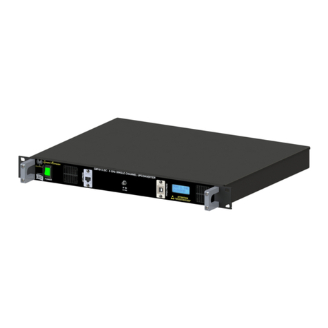
The QM1003-0.5-18-2 is a Dual Channel RF Downconverter housed in a 1U box. The QM1003-0.5-18-2
is controlled either through the onboard USB or TCP/IP connection. The QM1003-0.5-18-2 delivery kit
contains a user manual, power supply, and USB A-
µ
B cable. A model of the QM1003-0.5-18-2 is shown
below in Fig. 1.1.
Figure 1.1: QM1003-0.5-18-2 Dual Channel RF Downconverter system
The QM1003-0.5-18-2 Dual Channel RF Downconverter has been equipped with Option -100, which adds
Local Oscillator (LO) sources, making the QM1003-0.5-18-2 a self contained system, requiring only the
externally applied RF or IF signals for proper operation. Option -205 shifts the IF frequency range from
750-1250MHz to 2-3GHz. The Local Oscillators (LOs) in the QM1003-0.5-18-2 are locked to a common
internal reference. The user has the option of supplying their own reference through the BNC connector
located on the back panel of the QM1003-0.5-18-2.
Quonset Microwave Revision 1.0.0 4

QM1003-0.5-18-2 Dual Channel RF Downconverter User Manual
3. System Block Diagram
A system block diagram for the QM1003-0.5-18-2 Dual Channel RF Downconverter is shown in Fig-
ure 1.2. Internal attenuators in the downconverter are controlled digitally via a microcontroller, which
interfaces to a PC through USB or TCP/IP. The microcontroller outputs basic status messages on a 32-
character Liquid Crystal Display (LCD) mounted on the faceplate of the unit. An internal 10 MHz reference
is phase-locked to all of the internal LOs, with a BNC-F connector providing the option for LOs to lock to
a user-provided 10 MHz external reference. An additional BNC-F connector outputs a 10 MHz reference
for use by external test equipment. Switching between the internal and external LO reference is controlled
by the microcontroller.
Figure 1.2: QM1003–0.5–18–2 Downconverter Block Diagram
Quonset Microwave Revision 1.0.0 5

QM1003-0.5-18-2 Dual Channel RF Downconverter User Manual
2
Firmware Updates
In This Chapter
1. Introduction..............................................
7
2. Firmware Update Files . . . . . . . . . . . . . . . . . . . . . . . . . . . . . . . . . . . . . . . .
7
3. FPGA Firmware Updates . . . . . . . . . . . . . . . . . . . . . . . . . . . . . . . . . . . . . .
8
4. PIC Firmware Updates . . . . . . . . . . . . . . . . . . . . . . . . . . . . . . . . . . . . . . . .
15
Quonset Microwave Revision 1.0.0 6

QM1003-0.5-18-2 Dual Channel RF Downconverter User Manual
1. Introduction
The QM1003-0.5-18-2 Dual Channel RF Downconverter is continually being improved and may require
firmware updates to correct problems in previous firmware versions or to add new features that were not
yet implemented in previous firmware versions. Table 2.1 details Firmware Revisions that have been
released and which features they fixed or introduced.
Table 2.1: PIC Firmware Revision History
PIC Firmware Version Reason To Update
v1.0.0 N/A (Initial release)
FPGA Firmware Version Reason To Update
v1.0.0 N/A (Initial release)
2. Firmware Update Files
The required files to perform firmware updates are uploaded onto the Quonset Microwave FTP server
and need to be downloaded and extracted to a location on the computer performing the update prior to
continuing.
Firmware updates can be obtained by clicking the following link and navigating to the download link in the
Software tab:
http://www.quonsetmicrowave.com/QM1003-0.5-18-2-p/qm1003-0.5-18-2.htm
The zip files contain the necessary files required to perform the firmware updates. PIC Firmware Updates
require *.hex files and FPGA Firmware Updates require both *.bit files and *.mcs files. If the firmware up-
date zip file contains all three files, it is recommended to upgrade both PIC and FPGA firmware versions
to ensure proper performance as they likely work together and require each other for correct interaction.
Quonset Microwave Revision 1.0.0 7

QM1003-0.5-18-2 Dual Channel RF Downconverter User Manual
3. FPGA Firmware Updates
The QM1003-0.5-18-2 Control Board uses a Micron™ serial flash and a Xilinx® FPGA. Micron™ serial
flash are not currently fully supported by the Xilinx® iMPACT programming tool. The following sections
demonstrate the steps required to successfully configure the iMPACT software and load a Micron™ flash.
Xilinx® iMPACT
Xilinx® iMPACT Standalone Programmer is included in the Xilinx® ISE Lab Tools and is used in this
guide. ISE Lab Tools are available for free download using the following link:
https://www.xilinx.com/member/forms/download/xef.html?filename=Xilinx_LabTools_14.4_P.49d.3.0.tar
Note: All Xilinx® software downloads require Name and Address Verification in compliance with U.S.
Government Export Regulations prior to downloading.
System Environment Variable
A system environment variable must be set to allow the iMPACT software to skip its ID Check of the
Micron™ flash. In Microsoft Windows, this is done through System Properties. In Microsoft Windows 10,
click the Start Button and type "Edit the system environment variables" and click on the "Environment
Variables" button. The Environment Variables window is divided into two sections, User Variables and
System Variables. A new System Environment Variable must be created by clicking "New" in the System
Variables section. In the New System Variable window, enter the following:
Variable name: XIL_IMPACT_SKIPIDCODECHECK
Variable value: 1
USB Cable Connection
A standard USB 2.0 A-Male to B-Male Cable can be used to connect the computer to the QM1003-0.5-
18-2. The A-Male end of the cable connects to the computer and the B-Male end of the cable connects
to the QM1003-0.5-18-2 in the port on the back panel labeled FPGA PROG.
Quonset Microwave Revision 1.0.0 8

QM1003-0.5-18-2 Dual Channel RF Downconverter User Manual
Programming with iMPACT
Figure 2.1: iMPACT: Automatically create project
When iMPACT is started, it will first ask if you want it to create and save a project file for you. Choose ’No’,
as reusing projects sometimes results in outdated files being programmed, which were saved in previous
sessions.
Figure 2.2: iMPACT: Manually Create Project
Similarly, select ’Cancel’ when it asks you to load or create a new project next.
Quonset Microwave Revision 1.0.0 9
Table of contents
Other Quonset Microwave Media Converter manuals

Quonset Microwave
Quonset Microwave QM1013-101 User manual

Quonset Microwave
Quonset Microwave QM1004A-2-18 User manual

Quonset Microwave
Quonset Microwave QM1003-2-18 User manual

Quonset Microwave
Quonset Microwave QM1004-8-12-100 User manual

Quonset Microwave
Quonset Microwave QM1004-2-18 User manual

Quonset Microwave
Quonset Microwave QM1013-102 User manual