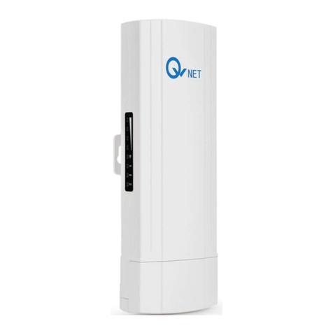
QWNET CPE5450FIT User manual

1
CPE5450FIT Quick Start Guide
Ver1.0
Aug,2019
Packing list
Product pictures

2
H CPE (Host CPE)C CPE (Client CPE)
1.Preparation for installation:
1-0 Shake the devices (CPE5450FIT) separately, to check if the device is damaged from
shipment, if you can hear some noise from inside of the device, and you suspect it maybe
PCBA board loosened, please contact us, we will help check if you need a replacement.

3
1-1 Move front cover
1-1-1 Push and then pull the front cover out
1-1-2
1-2Application case 1:
CPEs work with your router, to extend Wi-Fi signal, (e.g.from A building to B Building)

4
1-2-1 Ensure you know the CPE kit are ready for installation
This step is to verify wireless connection between both CPE5450FIT (both Host and Client), to make sure they
are pre-configured and can talk each other, It also helps you to be familiar with the product and prevent any
defectiveitem caused by delivery or by other reason etc.
1-2-1 Using both a router and a computer to verify if the devices are talking each other.
SketchDiagram
Test equipment list:
CPE5450FIT1 pair (2PCS, Host and Client)
Wi-Fi router /cabled router 1pcs
Computer (Laptop)1 set
Ethernet Cable 4pcs
POE Power Adapter 2pcs (Ethernet Cable Length:<60M, or 194ft)
1-2-1-1 Use Ethernet cable to connect POE port of power adapter to LAN port of CPE5450FITHost。

5
1-2-1-2 Use Ethernet cable to connect WAN port of CPE5450FITHost to LAN port of Wi-Fi Router
1-2-1-3 Use Ethernet cable to connect POE port of power adapter to WAN port of CPE5450FITClient
1-2-1-4 Use Ethernet cable to connect LAN port of CPE5450FITClient to computer

6
1-2-1-5 Set range between CPE5450FITHost and CPE5450FITClient : 3 meters(around 10 feet) is
recommended, without obstacle between 2 CPEs
1-2-1-6 Turn on all equipment, especially check as below to see if 2 CPE5450FIT are turning on, wait for 1
minute
Light is on Light is not on
1-2-1-7 Light information
Normal lights are as followings:

7
1-2-1-8 Ping IP address of the Wi-Fi router (some is:192.168.1.1 or 192.168.0.1) on the PC
You could find IP of router on label (normally located on bottom of the router), following example is for your
reference
Following is 192.168.1.1 , Win7 OS for example.
A. Click “Windows” icon
B. Input command “ping 192.168.1.1 –t”
C. Click “enter” to
Ping 192.168.1.1 –t
Following messages indicates the CPE5450FIT devices are working well.

8
1-2-2 The default password for the device is : 66666666
1-2-3 IP address for both Host(H) CPE and Client (C) CPE5450FITare: 192.168.188.253, you could log into
the device via page to change SSID and password of the device.
1-2-3 Changing SSID and password
1‐2‐3‐1ChangingHost(H)CPE’sSSIDandPassword
1-2-3-1-1 Set IPv4 IP address or IPv6 IP address of the PC to “192.168.188.22”(or 192.168.188.11 etc.),
1)Right Click Network Icon
2)Select Open Network and Sharing Center

9
3)Change adapter settings
4)Local Area Connection
5)Right Click and Select Properties

10
6)Select Internet Protocol Version 4 (TCP IPV4),try IPV6 if it doesn’t work.
7) Select Properties

11
8)Select Use the following IP address
9)Input IP address 192.168.188.xx (“xx” is between 0~251,e.g.22)

12
10) Left Click to automatically input Subnet mask:255.255.255.0
11) Subnet Mask 255.255.255.0

13
12) Click OK
13) Click Close
14) Login CPE5450FIT Host’s Webpage, use IE or Firefox browser is recommended. Input IP
address:192.168.188.253
15) Input Password: admin

14
16) Click Login and
1-2-3-1-2 ‐ClickWi‐FiSettings
1‐2‐3‐1‐3‐ChangeSSIDandpassword

15
1‐2‐3‐2ChangingClient(C)CPE’sSSIDandPassword
Step1‐PoweroffHost(H)CPE
Step2‐ClickWi‐FiSettings
Step3‐ChangeSSIDandpassword

16
1-3Application case 2 :
CPEs are used for wireless video transmission with camera(s) (e.g.from A building to B Building)
1‐3‐1Ensure you know the CPE kit are pre-configured and ready for installation, using both a router
and a computer to verify if the devices are talking each other is recommended. Please refer to
step 1-2-1 (from step 1-2-1-1 to 1-2-1-8)
1-3-2If you don’t have a router, please use a computer to check according to following procedure.
Sketch Diagram
Test Equipment List:
CPE5450FIT 2pcs
Computer (Laptop)1 set
POE Power Adapter 2pcs(Ethernet Cable Length:<60M, or 194ft)
Ethernet Cable 3pcs

17
1-3-2-1 Connect CPE5450FITClient (C) to computer and power adapter as following:
1-3-2-2 Connect CPE5450FITHost (H) to power adapter as following:
1-3-2-3 Set range between CPE5450FITHost and CPE5450FITClient: 3 meters(around 10 feet) is
recommended, without obstacle between 2 CPEs :
1-3-2-4 Turn on all equipment, especially check as below to see if 2 CPE5450FIT are turning on, wait for
1 minute
Light is on Light is not on

18
1-3-2-5 Light information
Normal lights are as followings:
1-3-2-6 Set IPv4 IP address or IPv6 IP address of the PC to “192.168.188.22”(or 192.168.188.11 etc.),
Please refer to above step 1-2-3-1 (from step 1 to 16) , and
Click Login
AP BSSID will be a MAC address, and there will be a green tick. “V”. It shows the CPE devices are working ok.
Otherwise it will be a red mark” ”.
(Don’t forget to change IPV4 setting back to “Automatically assign the IP address” on your computer after the
test.)
1-3-3 Remarks: Please be kindly noted that currently the devices don’t support cell phone (i.c. iPhone )
to access web page to configure directly.

19
1-4 Installation procedure
Block Diagram
Equipment:
CPE5450FIT1 pair (2PCS)
Camera 1pcs
DVR/NVR1pcs
Ethernet Cable 4pcs
1-4-1 Use Ethernet cable to connect WAN port of CPE5450FIT Clientto IP camera
1-4-2 Use Ethernet cable to connect LAN port of CPE5450FITClient to POE port of power adapter

20
1-4-3 Use Ethernet cable to connect LAN port of CPE5450FITHost to POE port of power adapter
1-4-4 Use Ethernet cable to connect WAN port of CPE5450FITHost to NVR/DVR
1-4-5 Turn on all equipment, especially check as below to see if 2 CPE5450FIT are turning on, wait for 1
minute, then you could see video of camera on monitor
Light is on Light is not on
Table of contents
Other QWNET Wireless Access Point manuals