R9 Technology SN400 User manual

User Guide
Copyright © 2021 R9 Technology Inc. All rights reserved. i
SN400 Sensor Node Hardware User Guide
January 2021
Release 1.7
R9 Technology
17217 Waterview Parkway Suite 1.202Y
Dallas, TX 75252
www.r9technology.com

User Guide
Copyright © 2021 R9 Technology Inc. All rights reserved. ii
Document Revisions
Date Version
Number Document Changes
09/28/2010 R1.4 Edit to pair button led flash info, other minor edits
01/11/2021 R1.5 Change DC adapter voltage to 3.0V, other minor edits.
01/21/2021 R1.6 Updated battery information
03/26/2021 R1.7 Updated battery information

User Guide
Copyright © 2021 R9 Technology Inc. All rights reserved. iii
Table of Contents
1 Introduction ................................................................................................................................................................ 4
2 SN400 Product Label ............................................................................................................................................... 5
3 Wireless Operating Band (Antenna) ................................................................................................................. 7
4 Power ............................................................................................................................................................................. 7
5 Indicators and Buttons ........................................................................................................................................... 9
6 Physical Dimensions ............................................................................................................................................. 11
7 Installation ................................................................................................................................................................ 11
8 Troubleshooting ..................................................................................................................................................... 13
9 Sales and Warranty Policy ................................................................................................................................. 13
6 Specifications ........................................................................................................................................................... 14
7 Certifications - United States FCC Statement ............................................................................................. 15

Copyright © 2021 R9 Technology Inc. All rights reserved. 4
1 Introduction
This User Guide covers specific hardware features of R9 Technologies model SN400 sensor
node. Several SN400 devices can accumulate electronic sensor data, and then wirelessly
transmit this sensor information to a single gateway device (wireless sensor network).
The gateway device will then use an LTE wireless data link to transfer this sensor data to
a database located on an internet-based server. The database can be used by customers
to view and analyze the gathered sensor information. Because the SN400 node has much
lower cost, complexity, and power requirement than the gateway device, the overall
system cost and flexibility is optimized.
The SN400 device’s position in the overall network can be seen in the diagram below.
The SN400 “Piconode” device is at the far-right end of the network diagram. It gathers
sensor information using wired sensors, which will, ultimately, be viewed and analyzed
on a user’s personal computer or smart device using a web-browser. Alerts which are
received via SMS text can also be implemented using the R9 web-based system.
The SN400 sensor node has four ports, each port can support one cabled sensor (for
example, temperature, humidity, door closure, tank liquid level, light level). It is also
possible to support multiple data types on one port, for example temperature and
humidity can be read from the same cabled sensor. Cabled sensors are plugged into the
SN400 using a three-pin connector. The connector is keyed, so the sensors cannot be
installed using the wrong orientation. Typically, each SN400 sensor port is provisioned
at the factory for a specific sensor type (analog, digital, specific communication format).
Therefore, specific sensors will need to be plugged into specific port numbers. The

Copyright © 2021 R9 Technology Inc. All rights reserved. 5
SN400 Installation Guide and R9 Online Portal User Guide contains information on
specific sensors and associated port numbers. Also, when onboarding your system on
the R9 web portal, you will be guided through the process of inserting wired sensors into
the SN400. The onboarding process is customized for specific sensing applications.
The sensor node device is typically mounted to equipment, and then cabled sensors are
applied to specific areas for sensing. For example, a node device is attached externally to
a refrigerator, and then a cabled temperature sensor is routed inside the refrigerator to
measure temperature.
For simple installations, the SN400 node can be installed inside a room, or
refrigerator/freezer, without cabling for the measurement of temperature. If installed
inside a refrigerator/freezer, wireless range may be diminished (typically by one third to
one half), but should be adequate for connection to a nearby gateway device.
The SN400 sensor node requires an external DC power source, or two AAA alkaline
batteries to operate. The sensor node does not have a power switch. When power is
applied by DC jack or insertion of batteries, the device will power on and automatically
begin to broadcast information to allow synchronization with, and connection to a nearby
gateway that is also powered on. Note that in order to pair with (connect to) a gateway
device, all sensor node devices should be setup first, using the online R9 portal. Refer to
the R9 Online Portal User Guide for information on how to onboard and configure the
gateway and sensor nodes in your monitoring system.
2 SN400 Product Label
The SN400 product label located on the side of the device will indicate several important
features of the device.

Copyright © 2021 R9 Technology Inc. All rights reserved. 6
1. The MAC ID, circled in red, in the picture below is unique to a specific SN400 device.
The last 5 digits of the MAC ID will be entered into the online portal system during
setup, and is used to identify the SN400 in the system. The last 5 digits of the serial
number is also entered.
2. The complete model number of the SN400 device indicates the specific
configuration of a particular device variant. For example, sensor port configuration,
wireless bands of operation, enclosure color, etc.
A typical model number is SN400-D1AAA. This part number indicates:
D1 – port configuration: Port 1 and 2 are set up for digital pulse counting, Port 3
is digital one wire, Port 4 is digital input.
A(1) - Antenna: Internal 915 MHz. ISM band antenna is provisioned and
selected.
A(2) - Power: Powered by internal AAA batteries.
A(3) - Enclosure: Indoor plastic case, color black.
In plain terms, the specific model/part number SN400-D1AAA has the following sensor
port configuration:
Port 1: temperature sensor (digital pulse count)
Port 2: temperature sensor (digital pulse count)
Port 3: dual sensor, humidity and temperature (bi-directional digital one wire)
Port 4: Door Ajar (digital input by switch open/close)
Consult the factory for more information on available SN400 model number variants.

Copyright © 2021 R9 Technology Inc. All rights reserved. 7
3 Wireless Operating Band (Antenna)
The SN400 will use only the 915 MHz. ISM band (United States) to wirelessly connect
to, and transmit/receive data from the gateway device. The frequency range of operation
is 902 MHz. to 928 MHz. The SN400 uses a frequency hopping algorithm to minimize
generated noise and improve immunity from external RF interference. An 868 MHz.
ISM band (European) version of the SN400 is also available (SN401).
The SN400 915 MHz. antenna is PCB mounted and located internally to the enclosure.
Note that it is possible to connect an external antenna to the SN400 device. This is
supported only as an option, and should not be necessary in a typical application.
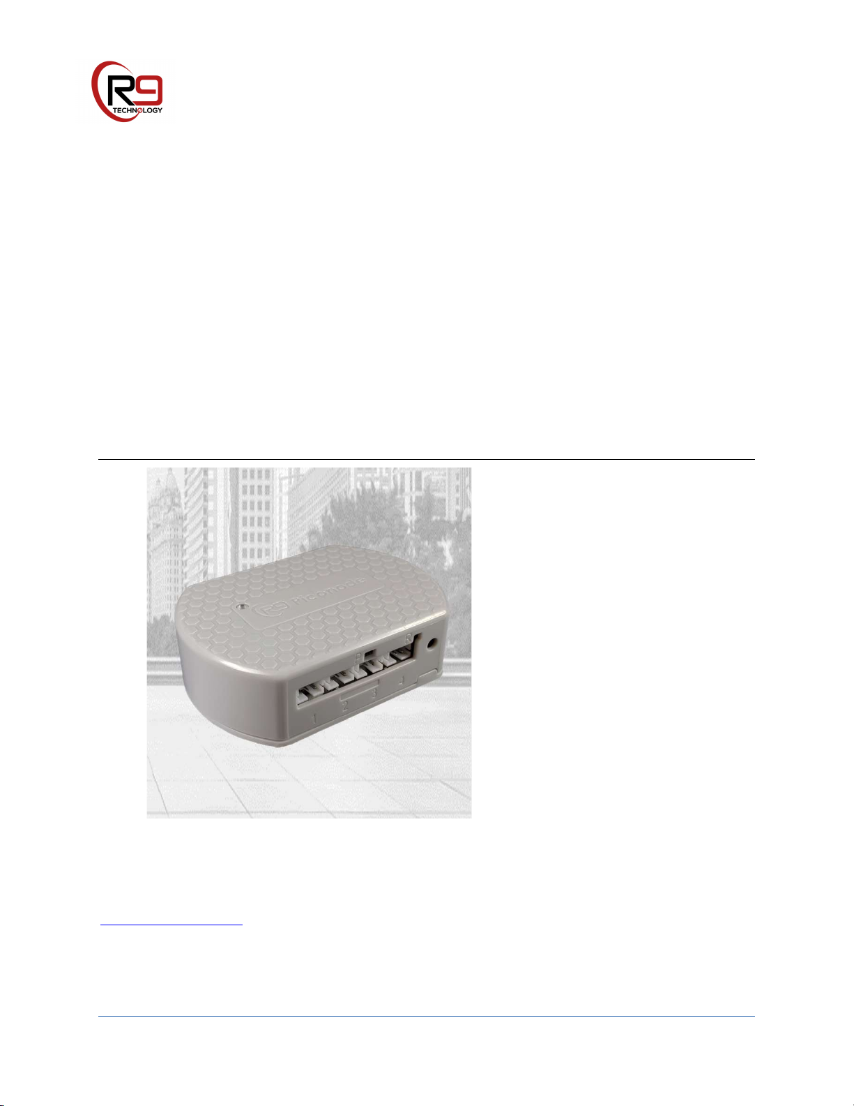
4 Power
The SN400 sensor node requires an external DC power source, or two AAA alkaline
batteries to operate. Typical installations will always use batteries for power. When
power is applied by DC jack or insertion of batteries, the device will power on and
automatically begin to broadcast information to allow synchronization with, and
connection to a nearby gateway that is also powered on. Note that in order to pair with
(connect to) a gateway device, a sensor node device must have been configured
previously in the online R9 portal. Refer to the R9 Online Portal User Guide for
information on how to onboard and configure the gateway and sensor nodes in your
monitoring system.
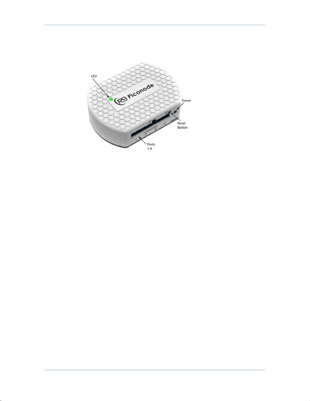
The sensor node does not have a power switch. Remove the battery compartment lid
located on the rear of the SN400 and install 2 AAA batteries in the correct orientation
(marked on battery holder) and replace lid. To open the battery lid, pull the small tab
toward the door, and lift at the same time (using your finger nail or small screw driver).
DC Power Supply: when using a DC power adapter, sensor values will not update if wall
power is interrupted. For this reason, it is not recommended to use a DC wall adapter,
unless absolutely necessary. Contact R9 Technology to purchase a DC wall adapter.
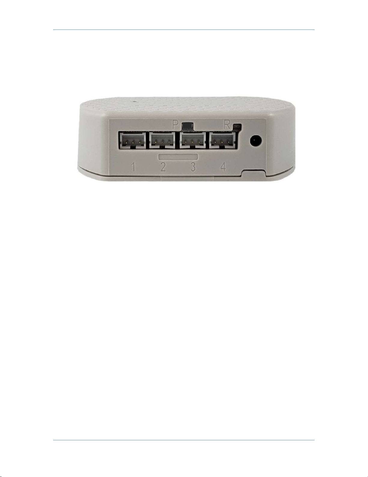
The power supply is +3.0V, center pin positive. The DC power supply can be
inserted into the sensor node without removing batteries.
The DC power supply must be plugged into a 120V 60Hz. AC wall outlet if
operating in the United States. The DC Jack output is then plugged into the
power input port on the SN400.

Copyright © 2021 R9 Technology Inc. All rights reserved. 8
An optional 220V AC, 50 Hz supply will be required in most parts of Europe
or Asia.
Batteries:
The sensor node can be powered from 2 AAA alkaline batteries. The
expected battery life will vary for each specific application. Average battery
life-span is approximately 2 years for the “Safezone” application (two
temperature probes and 15-minute reporting interval).
Batteries are not supplied with the sensor node, and should be inserted by
the customer at the time of SN400 installation. If the sensor node device is
not to be used for a long period of time, the batteries should be removed to
prevent their depletion.
o AAA alkaline batteries are recommended (can be purchased from
drug store, shopping center, etc.). AAA alkaline cells provide the
best value in terms of cost and battery longevity, at room
temperature conditions. Alkaline batteries are ok for use inside a
refrigerator (temperatures down to about 35F), although the
longevity will likely be reduced.
o Lithium AAA batteries: Lithium batteries should be used in
extreme cold environments (sensor node located inside a freezer
with temperature below 0F or -18C). Alkaline batteries do not
operate optimally at temperatures below 0F or -18C. Lithium
chemistry batteries operate at temperatures down to approximately
-40F = -40C. It is best to use Lithium batteries in freezer
environments (temperatures below 32F). Do not confuse Lithium
AAA cells with Lithium polymer rechargeable batteries.
o Rechargeable AAA batteries: recently, several types of AAA
equivalent rechargeable batteries have become commonly available.
NiMH (nickel metal hydride) AAA rechargeable cells have been
tested with the sensor node. NiMH cells have significant self-
discharge, and will lose 5%-20% of their charge per month.
Although rechargeable cells function, they are not recommended as
they require more frequent re-charging as compared to alkaline
cells.

Copyright © 2021 R9 Technology Inc. All rights reserved. 9
5 Indicators and Buttons
1. Reset Button (R) – Momentary “quick” press resets the SN400 to power-on
condition (initialize). The LED will quickly flicker red/green during power-on, or
when reset button is pressed.
2. Pair Button (P) – Momentary “quick” press will use the LED to indicate paired status
of the Node (to Gateway). See table on next page for pair button operation.
3. Power Input Port – Utilized for input of external DC power (3.3V) using DC jack.
External power supply sold separately.
4. Sensor Ports – Utilized to connect external, wired sensor probes.
5. Pair/Reset LED – Indicates SN400 network paired status, as well as reset or power-
up status. See table on next page.
The SN400 uses a red/green bi-color LED indicator to communicate the status of the sensor
node. To save battery power, the SN400 sensor node will briefly illuminate the LED. To
query the paired status of the SN400 without interrupting operation, a “quick” press of the
pairing button (P) will indicate the network pairing status (to gateway) using the LED
indicator. Long pressing the pairing button will cause the SN400 to clear its paired status to
a gateway, and it will start broadcasting to initiate a new connection to a nearby gateway.
Pushing reset does not clear the pairing memory or status. Pushing reset will cause the
SN400 to initialize to a power on state. The tables below cover detailed operation of the
pairing (P) and reset (R) buttons, as well as the LED indication.

Copyright © 2021 R9 Technology Inc. All rights reserved. 10
SN400 LED indication
-
power on
and
reset button
quick
press
Color
Blink
Count
Description
Red/Green
f
ast 6
The SN400 LED
will
illuminate
with a quick flicker
of both red and green colors on the LED. The
SN400 sensor node is initialized, but the gateway
pairing information is not erased. A small
screwdriver will aid in pushing the tiny button.
SN400 LED indication
-
pairing button
QUICK
press
Color
Blink
Count
Description
Red
quick 3
Indicates SN400 is on, and
IS NOT
paired
to a
gateway sensor network. The SN400 will
continuously broadcast to try and locate a
gateway to pair to. A gateway will not pair to a
node unless it is provisioned to do so in the
online portal.
Green
quick 3
Indicates SN400 is on, and
IS
paired
to a gateway
sensor network, as provisioned in the online
portal. Note that “paired” indicates the node
pairing memory is set with gateway information.
“paired” does not indicate the node is currently
communicating with a gateway (communication
happens infrequently based on sample interval,
typically 15 minutes).
SN
400 LED indication
-
pairing button LONG press
Color
Blink
Count
Description
Red
/Green
f
ast 6
Erase the gateway pairing memory. Depress the
pairing button for a count of five seconds and
then release. The LED will quickly flash
red/green six times to indicate that the gateway
pairing information has been erased. The SN400
will begin broadcasting to find a nearby gateway
to pair to. A small screwdriver will aid in pushing
the tiny button.

Copyright © 2021 R9 Technology Inc. All rights reserved. 11
6 Physical Dimensions
All dimensions are shown in millimeters.
7 Installation
To facilitate mounting, the SN400 is provided with two rear facing magnets for easy
attachment to a ferrous metal, steel surface. Alternatively, a fastener screw, or double-
sided adhesive foam tape can be used on the top flange for mounting to a wall or other
flat surface. The node will frequently be attached to large equipment, and should always
be located as high as possible on the equipment (for best wireless performance). Sensor
cables should always exit the bottom of the enclosure in a downward direction (for first
few inches) to prevent ingress of moisture or other contaminants. A separate document,
the SN400 Installation Guide is available that covers the installation of the SN400
product and cabled sensors, at a user site, for remote monitoring of sensor data.

Copyright © 2021 R9 Technology Inc. All rights reserved. 12
The image below shows the SN400 installed inside a refrigerator using integrated
magnets (attached to steel shelf frame). The external sensor ports are protected by the
refrigerator shelf from liquid spills. Ideally, the external ports should point downward to
prevent ingress of spills and liquids.
The image below shows the SN400 installed on the outside of a refrigerator using
integrated magnets. An external wired sensor is used to sense refrigerator temperature.

Copyright © 2021 R9 Technology Inc. All rights reserved. 13
8 Troubleshooting
The table below indicates common issues and resolutions for the SN400 sensor node.
Symptom
Issue
Resolution
Reset button works
properly, but pairing button
does not work. SN400 will
not connect to portal.
AAA batteries are low. When
batteries are low, there is
typically enough energy to
allow the SN400 to reset, but
not enough energy to run
other operations.
Replace AAA batteries.
9 Sales and Warranty Policy
Please download the sales and warranty policy document from our website at
www.r9technology.com. It is located online in the documentation section (under resources
tab).

Copyright © 2021 R9 Technology Inc. All rights reserved. 14
6 Specifications
Wireless 915 MHz ISM band connectivity for sensor data transfer (868 MHz. option)
Software-defined radio (SDR) chip-set
AES128 encryption providing secure sensor node communication
Provides local and remote digital temperature sensing
o Four channels: -30°C to 85°C ±0.6°C remote sensing temperature range (wired probe)
o Single channel: -20°C to 45°C local ambient temperature range (limited by batteries
on module)
Supports multiple digital probe types, including serial one wire, pulse counting, GPIO
(one bit)
Supports up to four channel analog input configuration (0V-10V)
External reset button
External network status button
Small (62.8 mm height x 72.9 mm width x 21.1 mm thickness) ABS plastic enclosure
o Integrated magnet system for attachment to metal surfaces, including refrigerator and
freezer.
o Mounting flange for use with screw-mount applications.
Bi-color LED indicator (red/green)
Built-in system sleep timer for lowest possible power consumption, and longest possible
battery life
Operated by Internal battery or external DC power supply
2x AAA alkaline battery power. (2+ years of battery life @ 15-minute reporting
intervals)
DC jack for external power input (0.65 mm, 3.0V)
-20°C to 45°C device temperature operating range (with batteries on module)
Optional external antenna can be configured
Optional external DC power supply

Copyright © 2021 R9 Technology Inc. All rights reserved. 15
7 Certifications - United States FCC Statement
Compliance Statement (Part 15.19)
This device complies with Part 15 of the FCC Rules. Operation is subject to the following two
conditions:
1. This device may not cause harmful interference, and
2. This device must accept any interference received, including interference that may cause
undesired operation.
Warning (Part 15.21)
Changes or modifications not expressly approved by the party responsible for compliance
could void the user’s authority to operate the equipment.
FCC Interference Statement (Part 15.105 (b))
NOTE:
This equipment has been tested and found to comply with the limits for a Class B digital
device, pursuant to part 15 of the FCC Rules. These limits are designed to provide
reasonable protection against harmful interference in a residential installation. This
equipment generates, uses and can radiate radio frequency energy and, if not installed and
used in accordance with the instructions, may cause harmful interference to radio
communications. However, there is no guarantee that interference will not occur in a
particular installation. If this equipment does cause harmful interference to radio or
television reception, which can be determined by turning the equipment off and on, the user
is encouraged to try to correct the interference by one or more of the following measures:
—Reorient or relocate the receiving antenna.
—Increase the separation between the equipment and receiver.
—Connect the equipment into an outlet on a circuit different
from that to which the receiver is connected.
—Consult the dealer or an experienced radio/TV technician for help.
FCC Radiation Exposure Statement:
This equipment complies with the FCC radiation exposure limits set forth for an
uncontrolled environment. This equipment should be installed and operated with a
minimum distance of 20cm between the radiator and all persons. This transmitter must not
be co-located or operating in conjunction with any other antenna or transmitter.
Table of contents