INSTRUCTIONS
X17™
PowerColor
TemperaturePhotocell
Factory Settings: 4000K and 60W
Selector Switch Caps
(Fig. 7).
Selector Switches(Fig. 8).
Power Color Temperature
Photocell
POWER (W) Selector Switch
Photocell Selector Switch
CCT Selector Switch
Fig. 9.
CAUTION: Be sure xture temperature is cool enough to touch.
Do not clean or maintain while xture is energized.
X17 XFU 80-60-40 IN-0921
Easy Answers
rablighting.com
Visit our website for product info
Tech Help Line
Call our experts: 888 722-1000
e-mail
Free Lighting Layouts
Answered online or by request
© 2021 RAB LIGHTING Inc.
Note: These instructions do not cover all details or variations in equipment nor do they provide for every possible situation during installation, operation or maintenance.
73710-RAB
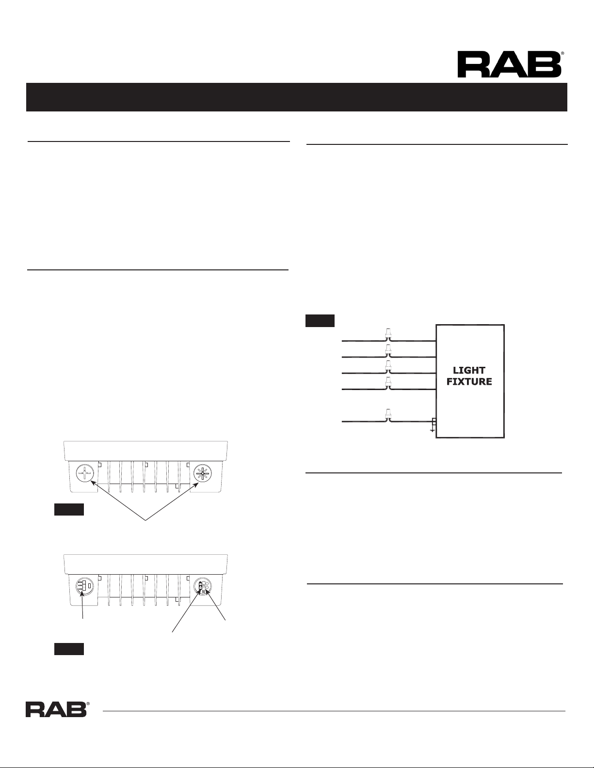
Selector Switch Caps
BROWN/BLACKLINE
WHITE/BLUECOMMON
PURPLE(+) DIM V+
GR AY
GREEN/YELLOW
(-) DIM V-
GROUND
To adjust the angle of the xture using the Trunnion (Fig. 6).
Pivot BoltsAngle Locking Screws
(not included)Fig 9.
Fixture(Fig. 6)
Pivot BoltsAngle Locking Screws