Table of Contents
1. Parts list
2. Tools required
3. Installation procedure
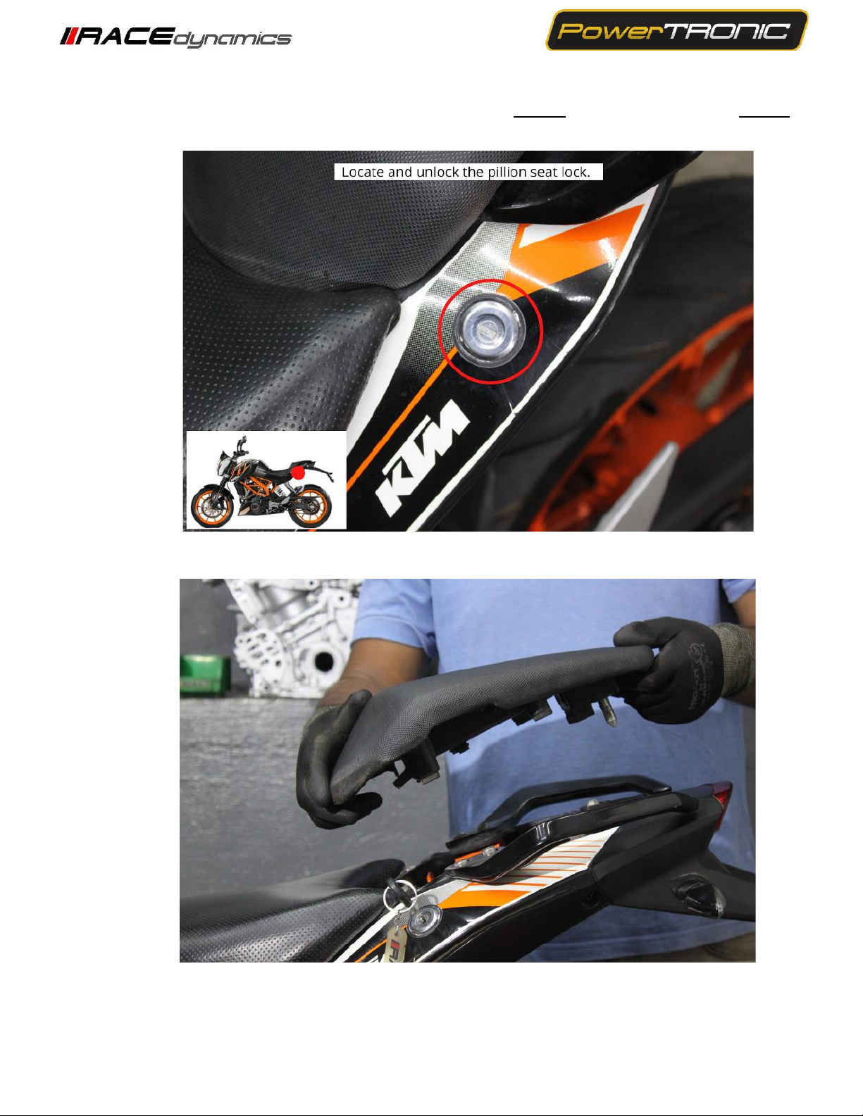
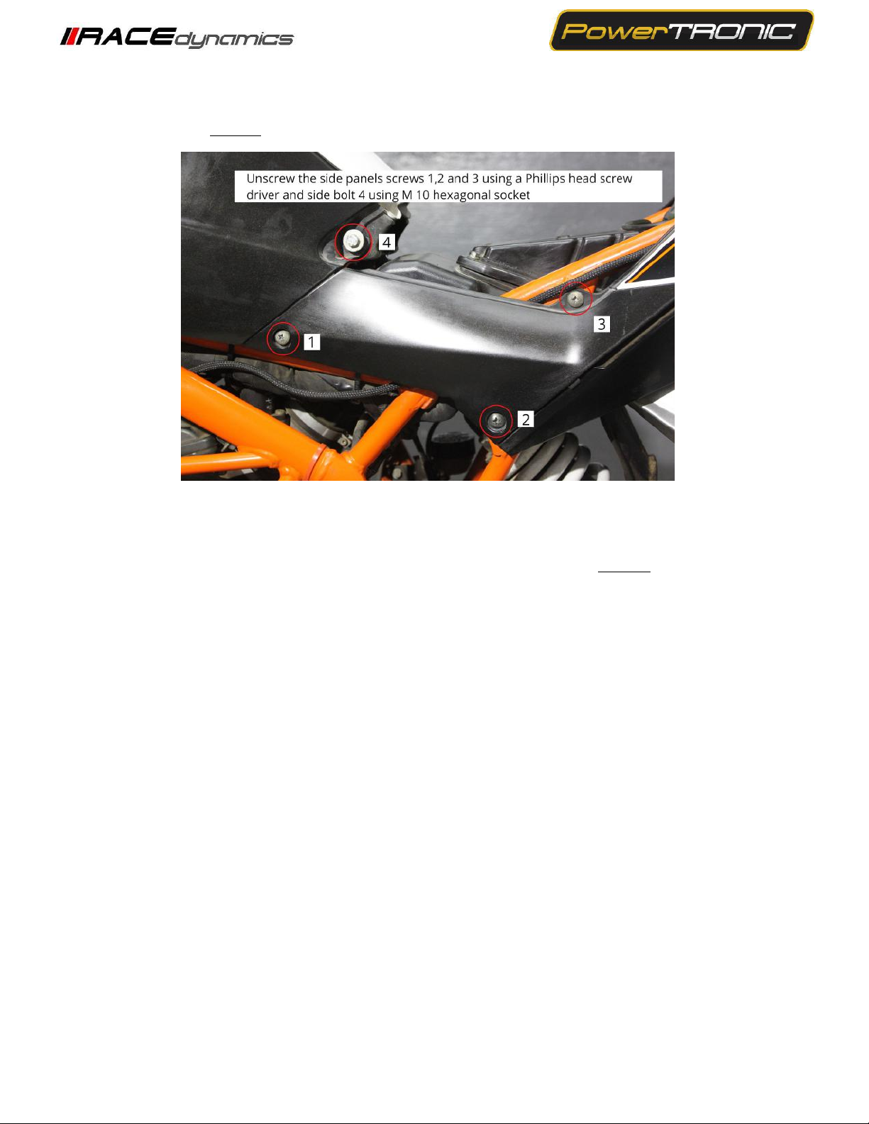
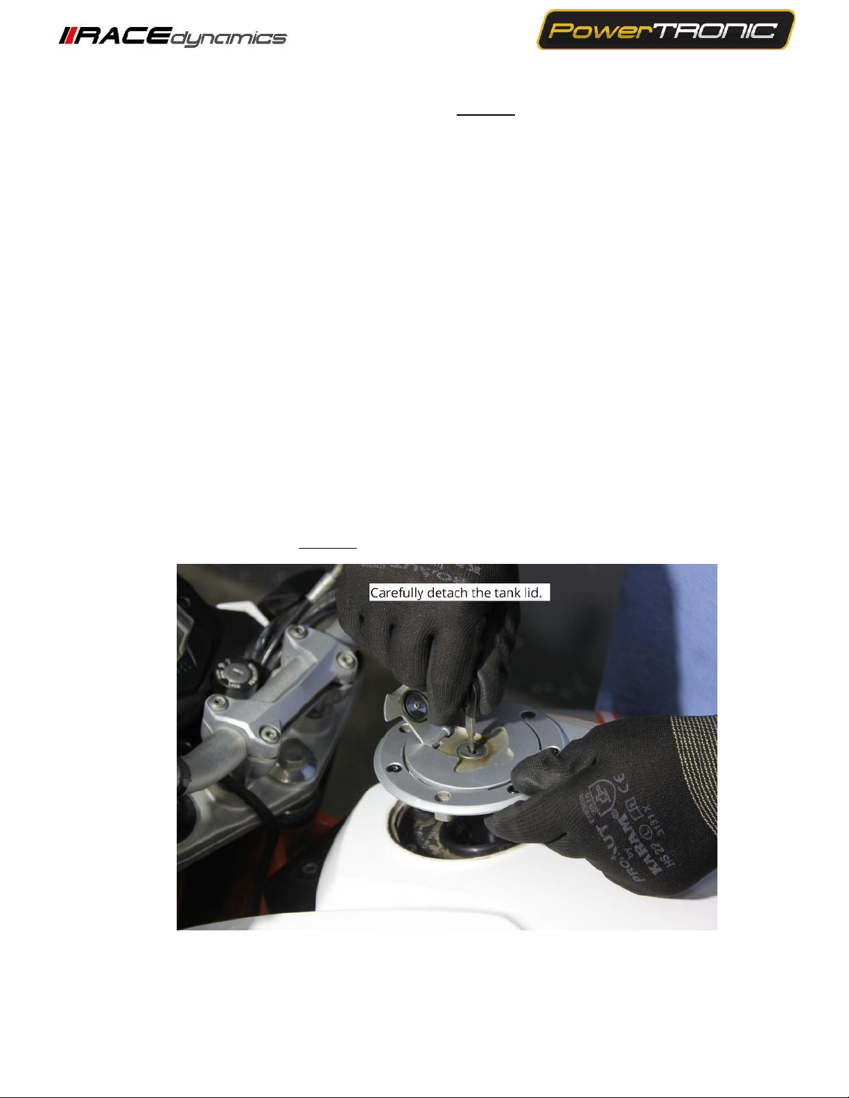
3.1 Removing panels, fairing etc
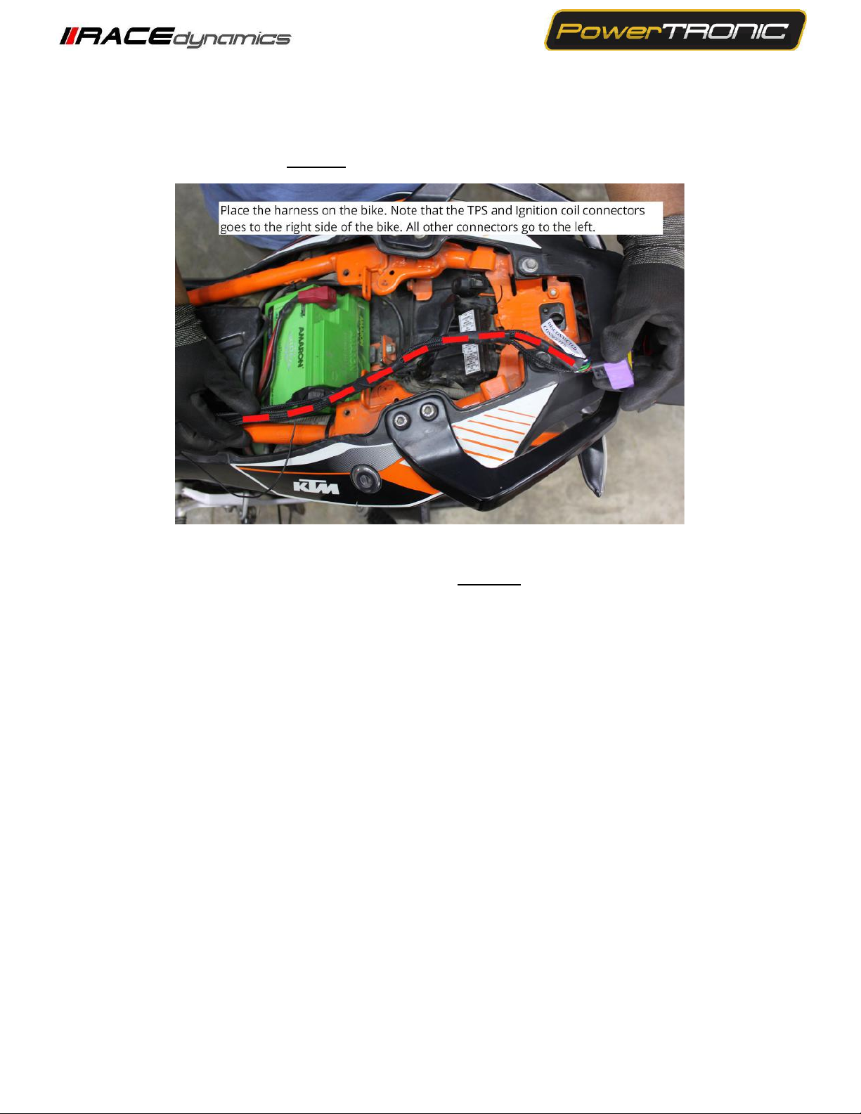
3.2 Routing the harness
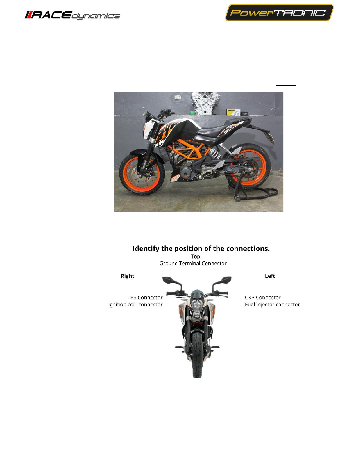
3.3 Fuel Injector Connector
3.4 Crankshaft position sensor
3.5 Ignition coil connector
3.6 Throttle Position Connector
3.7 Ground terminal
3.8 Securing the routed harness
3.9 Testing with Stock Coupler
3.10 Plugging in the PowerTRONIC
3.11 Attaching the panels, fairing etc
1. Parts list
Stand by unit
●Can be connected in place of the PowerTRONIC to run the bike in stock
mode if need be.
●Used for the verification of the connectors involved.
Bike specific harness contains the following connectors
●Fuel injector connector
●Spark/Ignition coil connector
●Throttle position sensor connector (TPS)
●Crankshaft position sensor connector(CKP)
●Map selection connector
●Quick shifter connector
●Ground terminal
Can be used to connect the PowerTRONIC to a laptop for throttle calibration or
changing maps
To secure wiring harness
User guide and Warranty card
M8, M10, M12, M17 Hexagonal socket
M10 T bar Hexagonal Socket wrench
Extension bar or Sliding T bar
Phillips head screwdriver