Racine Railroad Products 910215 User manual

1955 Norwood Court
Mount Pleasant, WI 53403
Phone: (262) 637-9681
Email: [email protected]
racinerailroad.com
Unit 3 Hartington Industrial Estate
Chesterfield Derbyshire, S43 3YF
Phone: 0330 164 1375
Email: [email protected]
racinerailroad.co.uk
Hydraulic Rail Profile Grinder
910215
Operating Manual

1955 Norwood Court
Mount Pleasant, WI 53403
Phone: (262) 637-9681
Email: [email protected]
racinerailroad.com
Unit 3 Hartington Industrial Estate
Chesterfield Derbyshire, S43 3YF
Phone: 0330 164 1375
Email: [email protected]
racinerailroad.co.uk
Hydraulic Rail Profile Grinder
910215
Record of Changes
Rev No.
Date
Description of Changes
Rev 1
4.2023
Initial release.
Rev 1.1
10.2023
Update Technical Support & Service information

910215 –Hydraulic Rail Profile Grinder
racinerailroad.com
racinerailroad.co.uk
4.2023 Rev 1
Original Instructions
Page 3of 30
Table of Contents
Section 1: Overview and Safety....................................................................................................................5
Hydraulic Rail Profile Grinder Overview........................................................................................................5
Environmental Protection..............................................................................................................................5
Safety Information.........................................................................................................................................6
Safety Terms .............................................................................................................................................6
Machine Use and Safety Precautions .......................................................................................................6
Section 2: Specifications and Installation......................................................................................................8
Specifications................................................................................................................................................8
Hydraulic fluid ........................................................................................................................................8
Hydraulic System Specification .............................................................................................................8
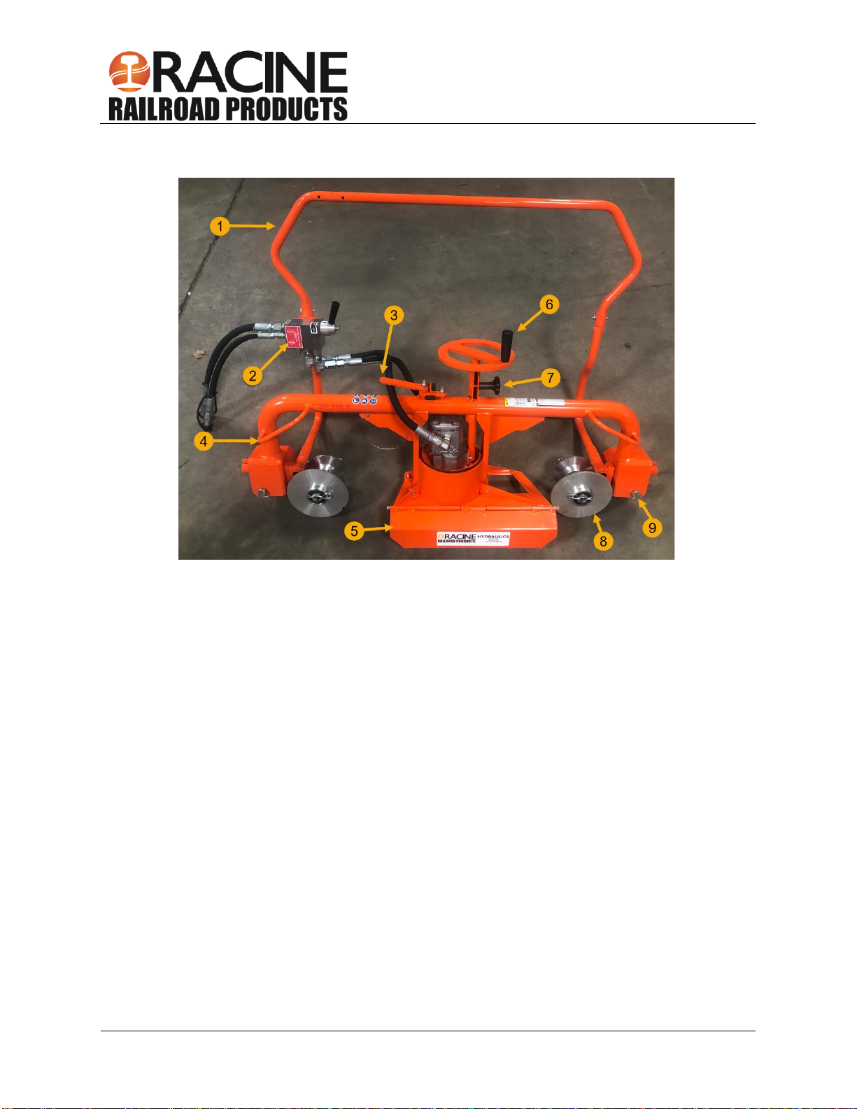
Components..................................................................................................................................................9
Installation...................................................................................................................................................10
Hose Requirements ....................................................................................................................................10
Hose Types .............................................................................................................................................11
Hydraulic Hose Recommendation...........................................................................................................12
Hydraulic Fluid Recommendation ...........................................................................................................12
Tool Connecting Procedures...................................................................................................................13
Disconnecting Hoses...............................................................................................................................13
Section 3: Tool Operation ...........................................................................................................................14
Personal Protective Equipment ...........................................................................................................14
Grindstone Installation.............................................................................................................................14
Grinder Functional Test...........................................................................................................................16
Stone Height Adjustment.....................................................................................................................17
Operation.................................................................................................................................................17
Frame Rotation ....................................................................................................................................18
Positioning on the Rail.........................................................................................................................18
Section 4: Maintenance...............................................................................................................................19
Troubleshooting ..........................................................................................................................................20
Maintenance Schedule ........................................................................................................................20
Troubleshooting ...................................................................................................................................21
Section 5: Parts and Service Support.........................................................................................................22
On-Off Rotary Valve Exploded View & Parts List................................................................................22
Motor Exploded View...........................................................................................................................24
Motor Exploded View Parts List...........................................................................................................25

910215 –Hydraulic Rail Profile Grinder
racinerailroad.com
racinerailroad.co.uk
4.2023 Rev 1
Original Instructions
Page 4of 30
Handle Exploded View & Parts List.....................................................................................................26
Frame Exploded View & Parts List .......................................................................................................27
Profile Grinder Exploded View.............................................................................................................28
Profile Grinder Exploded View Parts List.............................................................................................28
Section 6: Warranty Terms and Conditions ................................................................................................30

910215 –Hydraulic Rail Profile Grinder
racinerailroad.com
racinerailroad.co.uk
4.2023 Rev 1
Original Instructions
Page 5of 30
Section 1: Overview and Safety
Hydraulic Rail Profile Grinder Overview
Racine Railroad Products designs and manufactures equipment primarily for the repair and new
construction of rail and railroad tie track maintenance.
The Hydraulic Rail Profile Grinder uses a high-efficiency, pressure loaded hydraulic motor that provides
maximum power while reducing heat and minimizing energy waste.
The smooth-operating stone height adjustment is well within easy reach of the operator. Lifting handles
are balanced for ease in transport. Stone access panel and shaft lock make for easy stone removal. The
quick latch is easily adjustable for carriage positioning.
Use grinding discs with approximately 15.24 cm (6 inch) diameter and 7.62 cm thickness (3 inch). The
grinding discs must be suited for use at 3,300 rpm.
Over speed valves protect the motor and stone from excess RPM. Spark guard offer optimum protection.
Convenient handle with trigger guard automatically stops the tool operation when released.
Do not use this machine for other than its intended purpose.
Please read these instructions when using this tool, which can only be used for the specified purpose.
This instruction manual should be kept throughout the life of the tool.
The operator of this tool should:
•Have access to this operation instruction.
•Read and understand this operation instruction.
Note: Information in this document is subject to change without notice.
Environmental Protection
Comply with relevant national waste disposal laws and regulations. Waste electronic
devices cannot be treated as household waste.
Equipment, accessories, and packaging shall be recyclable.
Don't throw the discarded equipment in trash cans.

910215 –Hydraulic Rail Profile Grinder
racinerailroad.com
racinerailroad.co.uk
4.2023 Rev 1
Original Instructions
Page 6of 30
Safety Information
For safe installation and operation of this equipment, carefully read and understand the contents of this
manual. Improper operation, handling, or maintenance can result in equipment damage and personal
injury.
Only trained and authorized personnel should be allowed to operate this machine. In addition, all
personnel at the worksite should be aware of the safety concerns and their individual responsibilities prior
to working with this machine.
Please read and comply with all the safety precautions in this manual before operating this machine.
Your safety is at risk.
Safety Terms
DANGER indicates a hazardous operating procedure, practice, or
condition. If the hazardous situation is not avoided death or
serious injury will occur.
WARNING indicates a hazardous operating procedure, practice, or
condition. If the hazardous situation is not avoided death or
serious injury could occur.
CAUTION indicates a potentially hazardous operating procedure,
practice, or condition. If the hazardous situation is not moderate or
minor injury could occur.
Machine Use and Safety Precautions
Failure to follow safety precautions when operating this equipment can
result in serious injury or death to the operator or other persons in the
area.
Observe the following precautions whenever you are operating,
working on or near this equipment.
Do not use this machine for other than its intended purpose.
Do not make any modifications without authorization or written approval from Racine Railroad Products.
Replace all Racine Railroad Products and OEM parts with genuine Racine Railroad Products and OEM
parts. Using non-OEM parts may compromise the safety of the machine.
Do not wear loose clothing, jewelry, radio belts, etc., when operating, working on or near this equipment.
They can be caught in moving parts and may result in severe injury.
Always wear appropriate personal protective clothing when operating this equipment: e.g., orange safety
vest, hard hat, safety glasses with side shields, hearing protection, steel-toed safety boots, leather gloves,
dust respirator, etc.
Always lift heavy objects with the knees and legs, not the arms and back.
Always keep hands, arms, feet, head, clothing, etc., out of the operating area and away from all rotating
or moving components when operating, working on or near this machine.
Always make sure that all guards, covers, belts, hoses, and operating components are in good working
order and that all controls are in the appropriate position before starting the engine.

910215 –Hydraulic Rail Profile Grinder
racinerailroad.com
racinerailroad.co.uk
4.2023 Rev 1
Original Instructions
Page 7of 30
Always make sure that all safety equipment installed properly and are in good working order. Do not
operate the machine until unsafe conditions have been corrected.
Always operate in a well-ventilated area and make sure that the air filters, air filter covers, and muffler
are in good condition.
Always keep the machine clean and free of debris. Operate the machine in a safe and responsible
manner. Exercise caution when fueling, working on or near rotating or moving components, hot
components, and fuel systems. Be aware of potential fire hazards and prevent sparks, exhaust, etc., from
starting fires on the machine and/or work area.
Always comply with all instructions provided on any decals or placards installed on the machine and with
any relevant amplifying information provided in this manual or other general operating procedures.
Always disconnect the power source and make sure that all controls are in a safe position and install all
appropriate locking and safety devices before doing any of the following:
•Lubricating
•Adjusting
•Installing Tooling
•Making Repairs
•Performing Service

910215 –Hydraulic Rail Profile Grinder
racinerailroad.com
racinerailroad.co.uk
4.2023 Rev 1
Original Instructions
Page 8of 30
Section 2: Specifications and Installation
Specifications
Width ...................................................16 inch / 406 mm
Length .................................................45.5 inch / 1155 mm
Height .................................................35 inch / 889 mm
Weight .................................................95 lbs / 43.1 kg
Hydraulic pressure ..............................max. 2,150 psi / 150 bar
Hydraulic flow .....................................max. 10 gpm / 40 lpm
Idle speed ...........................................3,300 U/min / rpm
The machine is designed for outdoors use. It can be used at temperatures between -20 °C to 45 °C
(-4° F to 113° F).
The temperature of the hydraulic fluid should be at least 10 °C (50° F).
The statutory minimum distance must be observed around power lines.
Hydraulic fluid
The hydraulic fluid should meet the following requirements.
Viscosity (at 10 °C / 50 °F) .................95 cSt
Viscosity (at 38 °C / 100 °F) ...............27-42 cSt
Viscosity (at 60 °C / 140 °F) ...............16,5 cSt
Pour point ...........................................-10 °C / 14 °F
Viscosity index (ASTM-D2220) ...........min. 140
Flash point (ASTM-D92) .....................min. 171 °C / 340 °F
Pump wear test (ASTM-D2882) .........max. 60 mg
Demulsibility (ASTM-D1401) ..............max. 30 minutes
Hydraulic System Specification
The hydraulic unit should ensure a flow rate of at least 10 gpm / 40 lpm and pressure of
2,000 psi / 138 bar.
The pressure must be limited to 2,176 psi / 150 bar.
The measurement must be carried out at the minimum operating temperature of the hydraulic fluid by
10 °C (50 °F). Warm the hydraulic fluid if necessary.

910215 –Hydraulic Rail Profile Grinder
racinerailroad.com
racinerailroad.co.uk
4.2023 Rev 1
Original Instructions
Page 9of 30
Components
1 Handle
2 Connection Hydraulic Pump (Supply Flow and Return Flow)
3 Frame Rotation Locking Lever
4 Lifting Handle
5 Spark Guard
6 Stone Height Adjustment Hand Wheel
7 Hand Wheel Brake Knob
8 Guide Wheels
9 Roller
Excess weld from the ball of the rail can be removed with the Hydraulic Rail Profile Grinder. Use grinding
discs called cup stones with an approximately 6 inch / 15.24 cm diameter and 3 inch / 7.62 cm thickness.
The grinding discs must also be suited for use at 3,300 RPM.
The grinding disc is started as soon as the handle is pressed and stopped as soon as the handle is
released. There is an additional locking mechanism on the handle to prevent accidental activation of the
grinding disc.

910215 –Hydraulic Rail Profile Grinder
racinerailroad.com
racinerailroad.co.uk
4.2023 Rev 1
Original Instructions
Page 10 of 30
Installation
Unpacking Instructions
Upon receiving your Hydraulic Rail Profile Grinder promptly remove it from the shipping container.
Always keep the top side of container up. Inspect unit for damage which may have incurred during
shipping and report it to carrier for claim.
Tool Preparations
The Hydraulic Rail Profile Grinder requires some assembly before use. If the tool is used in cold
weather, preheat the hydraulic fluid by running the power source at low engine speed.
The fluid temperature should be at or above 50° F/10° C before use, when using recommended
fluids. Using too thick of fluid may result in tool damage.
Never stick foreign objects, fingers, or other extremities into the
moving mechanism. Failure to follow these instructions may lead
to severe personal injury or tool damage.
Hose Requirements
Check hydraulic hosed for cracks, leakage, and damage. If the hoses or couplers show any of these wear
characteristics, replace them before operating the tool. Never attempt to locate leaks with your hands,
personal injury may occur from pressure system.
It is not often necessary or advisable to use long hoses. All hoses must have an oil resistant inner surface
and an abrasion resistant outer surface. Each hose must have male pipe ends for most application.
Longer hoses can be used when necessary but can affect the operation of the tool due to resistance in
the hose.
If small diameter or long hoses are used, or if restrictive fittings are connected to the supply and return
ports, the pressure required to push the fluid through the system and back to the tank will be higher. This
will reduce tool power.
Important: Oil should always flow from the male coupler through the female coupler.
Note: The pressure increases in uncoupled hoses left in the sun. This may make them difficult for them
to connect. When possible after use, connect the free ends of the operating hoses together.

910215 –Hydraulic Rail Profile Grinder
racinerailroad.com
racinerailroad.co.uk
4.2023 Rev 1
Original Instructions
Page 11 of 30
The recommended minimum hose diameter for the pressure line hose
is 1/2” inside diameter. The pressure line hose must have a minimum
working pressure rating of 2500 psi [17.3 MPa].
It is recommended that the hose diameter for the return line hose is
5/8” diameter. If possible, should be greater than the pressure line
hose diameter.
These recommendations are intended to keep return line pressure
(back pressure) to a minimum acceptable level to ensure maximum
tool performance.
All hydraulic hose must meet or exceed specifications set forth by
SAE J517.
Hose Types
Hydraulic hose types authorized for use with the tool are:
1. Labeled and certified non-conductive.
•This is the only hose authorized for use near electrical conductors.
•Constructed of thermoplastic or synthetic rubber inner tube, synthetic fiber braid reinforcement,
and weather resistant thermoplastic or synthetic rubber cover.
2. Wire braided (conductive)
•This hose is conductive and must never be used near electrical conductors.
•Constructed of synthetic rubber inner tube, single or double wire braid reinforcement, and
weather resistant synthetic rubber cover

910215 –Hydraulic Rail Profile Grinder
racinerailroad.com
racinerailroad.co.uk
4.2023 Rev 1
Original Instructions
Page 12 of 30
3. Fiber braided (not certified or labeled non-conductive)
•This hose is conductive and must never be used near electrical conductors.
•Constructed of thermoplastic or synthetic rubber inner tube, synthetic fiber braid reinforcement,
and weather resistant thermoplastic or synthetic rubber cover.
The rated working pressure of the hydraulic hose must be at least 175 bar (2500 psi).
Hydraulic Hose Recommendation
Flow Per Circuit
Length Each Hose
Use
Inside Diameter
SAE Spec Hose
(Wire Braid)
SAE Spec Hose
(Fiber Braid)
GPM
LPM
Feet
Meter
Inch
MM
5 to 8
19 to 30
To 50
To 15
Both
1/2
13
SAE 100R1-8
100R7-8
5 to 8
19 to 30
51 to 100
15 to 30
Both
5/8
16
SAE 100R2-10
SAE 100R8-10
5 to 8
19 to 30
100 to 300
30 to 90
Pressure
Return
5/8
3/4
16
19
SAE 100R2-10
SAE 100R1-12
SAE 100R8-10
SAE 100R7-12
9 to 12
34 to 45
To 50
To 15
Both
5/8
16
SAE 100R2-10
SAE 100R8-10
9 v 12
34 to 45
51 to 100
15 to 30
Pressure
Return
5/8
3/4
16
19
SAE 100R2-10
SAE 100R3-12
SAE 100R8-10
SAE 100R7-12
9 to 12
24 to 45
100 to 200
30 to 60
Pressure
Return
3/4
1
19
25.4
SAE 100R2-12
SAE 100R1-16
SAE 100R8-12
SAE100R7-16
The rated working pressure of the hydraulic hose must be at least 2500 psi / 173 bar.
The temperature of the hydraulic fluid must be limited to 60° C (140° F).
Hydraulic Fluid Recommendation
Inspect hoses for cuts, crushing, leaks, or abrasion,
which may be a safety hazard or reduce fluid flows.
The following fluids work well over a wide temperature
range at startup, allow moisture to settle out, and resist
biological growth likely in cool operating hydraulic
circuits.
Others that meet or exceeds the specifications of these
fluids may also be used.
Type
Hydraulic fluid
Amsoil
AWH ISO 32
Chevron
Rando HD Premium Oil MV ISO VG 32
Rando HDZ ISO 32
Gulf
Harmony AW ISO Multi-Grade 32
Mobil
DTE Oil Excel 32
Schaeffer
Dilex Supreme Hydraulic Fluid w/
Dynavis ISO 46.
Shell
Shell Tellus S2 VX 32
Sunoco
Sunvis 1032 HVI Hydraulic Oil

910215 –Hydraulic Rail Profile Grinder
racinerailroad.com
racinerailroad.co.uk
4.2023 Rev 1
Original Instructions
Page 13 of 30
Tool Connecting Procedures
1. Stop the engine before connecting the tool and or hoses to the power unit, and when switching hoses
or tools.
2. Turn the hydraulic on/off valve to the off position before starting the engine.
Make sure all hoses are connected for correct flow direction to and from the tool being used.
When routing hose in the work area, position them where personnel will not be at risk of tripping over
them where vehicles can run over the hoses. Do not lay hose over sharp objects.
Pressurized fluid escaping from a damaged hose can penetrate the
skin and be injected in the body causing injury or death.
Do not pull on hoses to drag the power unit or tool.
Connecting Hoses
1. Wipe quick couplers with a clean lint free cloth before connecting them.
2. Depressurize the system.
3. Allow system and hydraulic fluid to cool if too hot to handle.
4. Securely connect the return (tank “R”) hose from the power source to the tool.
5. Securely connect the supply (pressure “P”) hose from the power source to the tool.
It is recommended that you connect the return hoses first and disconnect last to minimize or avoid
trapping pressure within the tool.
When connecting the quick couplers, the flow should run from male coupler to the female coupler.
The female coupler on the tool is the inlet. Quick couplers are marked with a flow direction arrow.
Pressurized fluid escaping from a damaged hose can penetrate the
skin and be injected in the body causing injury or death.
Do not pull on hoses to drag the power unit or tool.
Note: When possible, connect the free ends of uncoupled hoses to prevent build up in the hoses. The
sun can also increase pressure in the hoses and make connecting them difficult.
Disconnecting Hoses
1. Stop the hydraulic power source.
2. Depressurize the system.
3. Allow system and hydraulic fluid to cool.
4. Disconnect the supply (pressure) hose from the power source (pressure port) from the tool (IN port).
5. Disconnect the return (tank) hose to the hydraulic power source (return port) from the tool (OUT port).
6. To prevent contamination, always install dust caps over the hydraulic ports of the tool when
disconnected.

910215 –Hydraulic Rail Profile Grinder
racinerailroad.com
racinerailroad.co.uk
4.2023 Rev 1
Original Instructions
Page 14 of 30
Section 3: Tool Operation
Personal Protective Equipment
Before operating this machine, make sure that all general safety precautions are observed,
and that proper personal protective clothing is worn as described below.
At a minimum, operators should wear the following Personal Protective Equipment:
1. Safety Glasses
2. Hearing Protection
3. Hard Hat
4. High Visibility Safety Vest
5. Leather Work Gloves
6. Steel Toed Safety Shoes
Grindstone Installation
Grindstone with a diameter of 17.24 cm (6 inches) and a thickness of 7.62 cm (3 inch) must be used with
the Hydraulic Rail Profile Grinder. The grindstones must be suited for use at 3,300 RPM. Check the
grinding discs for damage before using. Damaged grinding discs may not be mounted.
1. Align the hole in the frame with the hole in
the motor spacer.

910215 –Hydraulic Rail Profile Grinder
racinerailroad.com
racinerailroad.co.uk
4.2023 Rev 1
Original Instructions
Page 15 of 30
2. Insert the stone locking pin through the holes
in the motor spacer. If the pin doesn’t slide
through the holes easily, adjust the stone
housing until it does.
3. Hold the stone locking pin in and turn the
stone by hand counter-clockwise (left) until
the pin locks the shaft.
4. Place the stone removal tool (option) around
the stone and loosen the stone.
5. Once the stone has been loosened, it can be turned by hand and removed.
6. Check that the blotter came off with the stone and didn’t stick to the inner surface of the backup
flange.
7. Check that the backup flange is pressed all the way on the spindle shaft. The square on the spindle
should slide into the square in the back of the backup.

910215 –Hydraulic Rail Profile Grinder
racinerailroad.com
racinerailroad.co.uk
4.2023 Rev 1
Original Instructions
Page 16 of 30
8. Use new blotters between the stone and
backup flange.
The blotters should be supplied with stones.
They are made of highly compressible
material and should not be more than 0.025”
thick.
9. Turn the spindle end until the backup flange
contacts the stone.
10. After the new stone has been installed, return
the stone locking pin to its storage location.
11. After mounting the new grinding disc let the
mounting disc run at full speed for a minute
before beginning grinding.
Grinder Functional Test
1. Make sure that the operating lever can be easily moved.
•If the operating lever is difficult to move, check for damage. If the Hydraulic Rail Profile Grinder is
damaged, stop the test and have the Hydraulic Rail Profile Grinder repaired.
2. Make sure that the grinding disc is securely mounted and that all safety devices are tightly fastened.
3. Connect the Hydraulic Rail Profile Grinder to the hydraulic unit.
4. Switch the hydraulic unit on.
5. Hold the Hydraulic Rail Profile Grinder tight with both hands.
6. Release the locking mechanism while pulling the operating lever.
7. The grinding disc must turn.
8. Let go of the operating lever.
•The grinding disc must stop.
•If the grinding disc does not turn or does not stop, op the test and have the Hydraulic Rail Profile
Grinder repaired.

910215 –Hydraulic Rail Profile Grinder
racinerailroad.com
racinerailroad.co.uk
4.2023 Rev 1
Original Instructions
Page 17 of 30
Stone Height Adjustment
The stone can be adjusted to a desired height by
turning the large hand wheel at the center of the
Hydraulic Rail Profile Grinder. The smaller knob
located under the hand wheel is used as a brake
to increase or decrease drag on the hand wheel.
Operation
A visual inspection is to be carried out before beginning work. In the event of damage, no work may be
carried out. Install hydraulic hoses away from walking and transport routes. Make sure that hydraulic
hoses are not installed over sharp edges. Make sure that the environment is well lit; set up additional
work lights if necessary.
1. Remove the dust covers from the quick couplings.
2. Clean the quick couplings.
3. Connect the Hydraulic Rail Profile Grinder with the return flow of the hydraulic unit.
4. Connect the Hydraulic Rail Profile Grinder with the supply flow of the hydraulic unit.
Ensure that the flow and return flow of the hydraulic unit are connected to the correct quick coupling.
When connecting the quick couplings, the flow should run from male coupler to the female coupler.
The female coupler on the tool is the inlet. Quick couplers are marked with a flow direction arrow.
The hydraulic unit must be switched off and without pressure for connection.

910215 –Hydraulic Rail Profile Grinder
racinerailroad.com
racinerailroad.co.uk
4.2023 Rev 1
Original Instructions
Page 18 of 30
5. Start the hydraulic unit.
6. Adjust the stone to the required height for
grinding the weld.
7. Hold the Hydraulic Rail Profile Grinder tight.
8. Turn the control valve to the “ON” position.
9. With the grinder at full speed, move it from
right to left into the weld.
10. Adjust the stone height and rotate the frame
as required for optimum results.
11. To stop the grinding disc, let go of the
operating lever and allow stone to stop before
removing from the rail.
12. Switch the hydraulic unit off after grinding.
13. Depressurize the system.
14. Allow the hydraulic fluid to cool.
15. Disconnect the supply flow from the Hydraulic Rail Profile Grinder.
16. Disconnect the return flow from the Hydraulic Rail Profile Grinder.
17. Protect the quick couplings with dust caps.
Frame Rotation
The Hydraulic Rail Profile Grinder’s frame can be set at any position within a 90° arc by loosening the
locking lever and pulling the frame toward the handle. Always turn the locking lever into a locked position
before grinding.
Positioning on the Rail
Place the Hydraulic Rail Profile Grinder on the rail with the two large diameter guide wheels on one side
of the rail and the other two smaller diameter wheels on the opposite side. The grinder should set on the
rail at each roller and roll back and forth freely.
When grinding with the Hydraulic Rail Profile Grinder, position the weld between the left set of wheels and
the stone housing (left and right are determined from the operator’s position at the handle).
Adjust the stone to the required height for grinding the weld.

910215 –Hydraulic Rail Profile Grinder
racinerailroad.com
racinerailroad.co.uk
4.2023 Rev 1
Original Instructions
Page 19 of 30
Section 4: Maintenance
It is highly recommended to practice regular check-ups and maintenance in accordance with the
usage
frequency to keep your tool in better condition and reduces total
run
ning
costs.
Do not perform maintenance on the machine while the hydraulic
power source motor is running or when hoses are connected.
All maintenance must be done with the tool disconnected from the
power source.
Cleaning and Maintenance Recommendations
•
Wipe
all external surfaces after each use with a clean, lint free cloth to remove surface
contaminants from the tool.
•
Store all
tools in an enclosed area to prevent the weather from contaminating their systems.
Safety Devices
When maintenance is complete, make sure the following:
•
The hydraulic
control valves are operable.
•
The hydraulic quick couplers and hoses are safe to use.
Storage Preparation
•Cover male and female hose whips.
•Store in the upright position. Secure tool to prevent it from being knocked over.
•Store the Web Grinder on a smooth level surface.
•The tool should be stored in a cool, dry environment which is not subjected to rapid temperature
changes.
Daily
Do not attempt to locate hydraulic leaks by feeling around hoses
and fitting with hand. Pin-Hole leaks can penetrate the skin.
•Wipe all tool surfaces, fittings, and couplings free of grease, dirt, and foreign materials.
•Inspect the tool, hydraulic system, hoses, and fittings for signs of leaks, cracks, wear, and/or damage.
Replace if necessary.
•To prevent contamination, always install dust caps over the hydraulic ports when disconnected.
•Inspect machine for damage and wear, replace as required.
Monthly
•Perform a detailed inspection of the systems hoses and fittings according to the hydraulic hose
operator’s manual and as stated in SAE standard j1273, May 1989 or latest revision.
Replace the hoses and/or fittings if necessary.

910215 –Hydraulic Rail Profile Grinder
racinerailroad.com
racinerailroad.co.uk
4.2023 Rev 1
Original Instructions
Page 20 of 30
Troubleshooting
Use the following chart as a guide to correct any problem you may experience with the too.
To determine the problem in operation of the grinder always check that the hydraulic power source is
supplying the correct hydraulic flow and pressure to the tool as listed in the table.
Be sure you are using an accurate flowmeter. Check the flow with the hydraulic fluid temperature at least
50° F / 10° C.
Maintenance Schedule
Components, for which wear and tear or even malfunction is determined during inspection, must be
repaired, or replaced as soon as possible.
Components
Inspection
Intervals
Entire device
Cleaning
The entire device must be cleaned with a lint-free cloth at
the end of the shift.
Visual inspection
The entire device must be checked for damage daily.
Damaged parts must be replaced.
Hydraulic system
Visual Inspection
The hydraulic system must be checked for leaks, cracks,
wear and/or damage daily. Damaged components must
be replaced.
Inspection
Check hoses and fittings for leaks monthly.
Hydraulic fittings
Visual inspection
To prevent contamination, always install dust caps over
the hydraulic fittings when disconnected.
Grinding stone
Visual inspection
Check the grinding stone for damage or wear before and
after each use. Damaged grinding discs may not be
used.
Grinding stone guard
and fasteners
Inspection
Check the grinding stone fasteners and guard. Keep
fasteners tight and guard in good condition.
Table of contents
Other Racine Railroad Products Grinder manuals