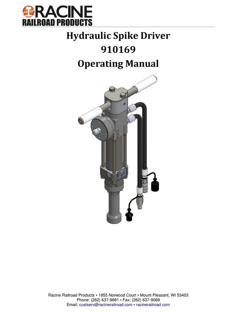
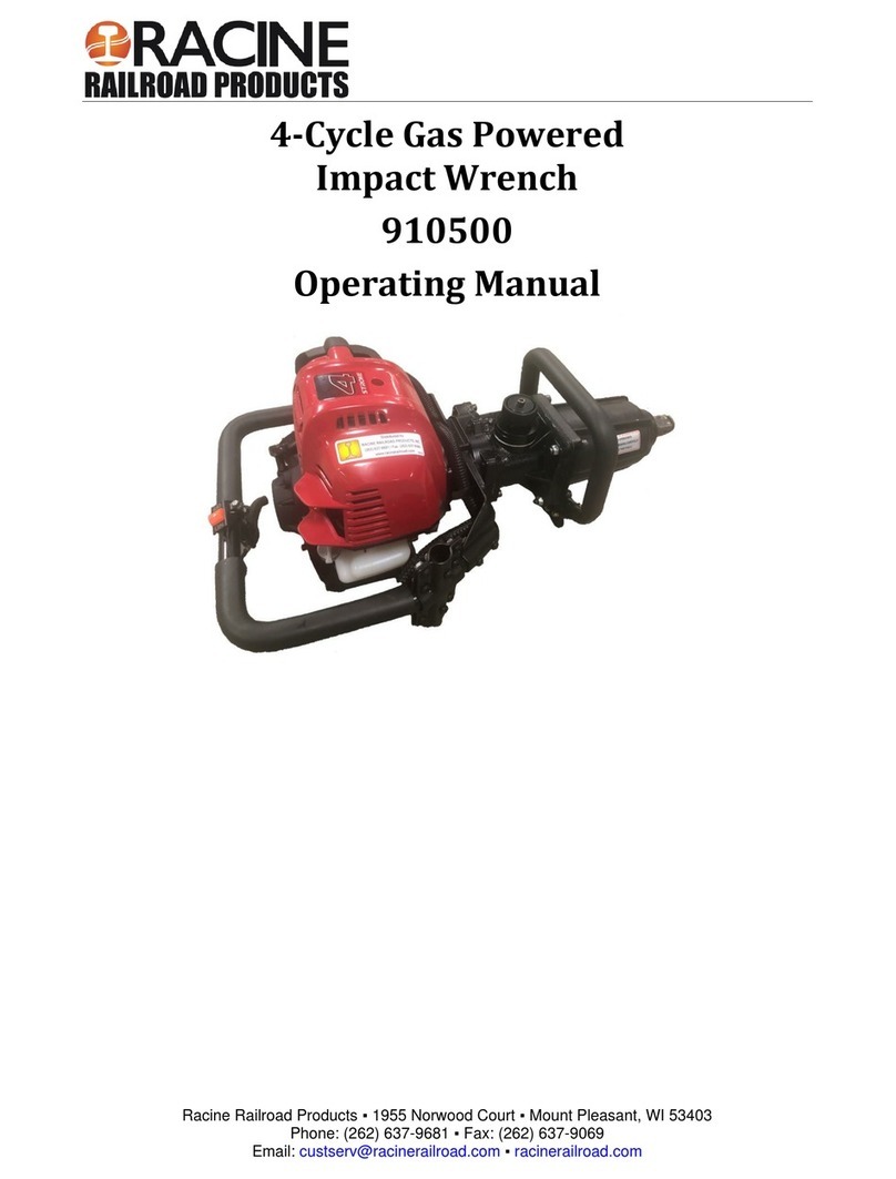
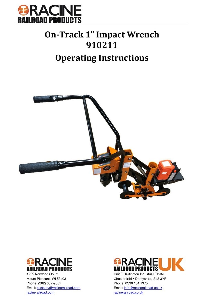
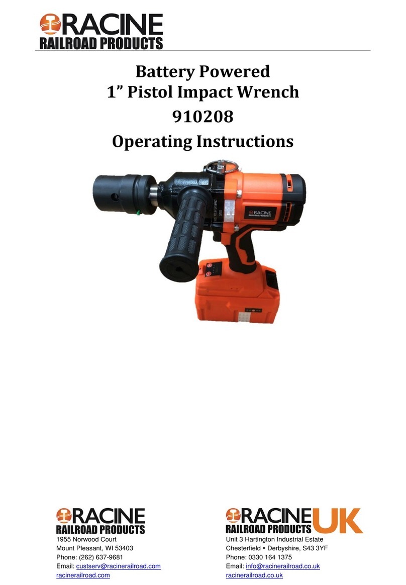
Racine Railroad Products 910193 User manual

910193 - Hydraulic Impact Wrench
Phone: (262) 637-9681
Email:
custserv@racinerailroad.com
www.racinerailroad.com
4.2021 Rev 2.1
Page ii
Hydraulic Impact Wrench [1” Drive]
910193
Record of Changes
Rev No.
Date
Description of Changes
Rev 1 Initial release.
Rev 2 10.2019 Update format, add parts list
Rev 2.1 4.2021 Update Service Parts List

910193 - Hydraulic Impact Wrench
Phone: (262) 637-9681
Email:
custserv@racinerailroad.com
www.racinerailroad.com
4.2021 Rev 2.1
Page iii
Table of Contents
Section 1: Overview and Safety .................................................................................................................... 5
Machine Name Overview .............................................................................................................................. 5
Warranty Terms and Conditions ................................................................................................................... 5
Safety Information ......................................................................................................................................... 6
Safety Terms ............................................................................................................................................. 6
Machine Use and Safety Precautions ....................................................................................................... 7
Section 2: Specifications and Installation...................................................................................................... 8
Specifications ................................................................................................................................................ 8
Components .............................................................................................................................................. 8
Torque Information ........................................................................................................................................ 9
Factors that Affect Torque ......................................................................................................................... 9
Installation ................................................................................................................................................... 10
Hose Requirements .................................................................................................................................... 11
Hose Types ............................................................................................................................................. 12
Hydraulic Hose Recommendation........................................................................................................... 12
Hydraulic Fluid Recommendation ........................................................................................................... 13
Tool Connecting Procedures................................................................................................................... 13
Disconnecting Hoses............................................................................................................................... 14
Section 3: Tool Operation ........................................................................................................................... 15
Cold Weather Operation.......................................................................................................................... 15
Section 4: Maintenance............................................................................................................................... 16
Impact Mechanism Removal, Cleaning and Installation ......................................................................... 17
Wrench Disassembly and Reassembly for Repair .................................................................................. 18
Motor Cleaning and Inspection................................................................................................................ 18
Motor Housing Disassembly.................................................................................................................... 19
Motor Housing Assembly......................................................................................................................... 20
Impact Intensity Adjustment .................................................................................................................... 21
Troubleshooting
......................................................................................................................................... 22
Section 5: Parts and Service Support ......................................................................................................... 24
Impact Wrench Assembly Service Parts ................................................................................................. 25
Impact Wrench Assembly........................................................................................................................ 26
Parts List .............................................................................................................................................. 28
Handle Assembly..................................................................................................................................... 29

910193 - Hydraulic Impact Wrench
Phone: (262) 637-9681
Email:
custserv@racinerailroad.com
www.racinerailroad.com
4.2021 Rev 2.1
Page 5of 30
Section 1: Overview and Safety
Machine Name Overview
Racine Railroad Products designs and manufactures equipment primarily for the repair and new
construction of rail and railroad tie track maintenance.
Our product line focuses on rail fastening application/removal/adjustment equipment, other tie material
(OTM) reclamation, wood and concrete railway tie repair, and tie plate handling/distribution.
The 1" Impact Wrench’s compact design allows the operator greater flexibility in tighter work areas.
Ergonomic handles give handhold positioning for either horizontal track bolts or working vertically for lag
screws. Optional auger adapter is available for tie drilling applications. Assist handle and whip hoses can
be orientated to operator preference.
The unit produces up to 2,500 ft-lbs of torque from the heavy-duty dual impact mechanism. Cast steel
motor body and trigger are durable with no formed metal fabricated parts.
Warranty Terms and Conditions
Warranty Period
Each new machine and new parts of our manufacture are warranted against defects in material and
workmanship for one year from the date of shipment from our factory.
When contacting customer service for factory parts, service or warranty support please provide the:
•Racine Railroad Products Model
•Serial Number
•Any locally assigned identification
Vendor Parts Warranty Period
Other equipment and parts used, but not manufactured by Racine Railroad Products, Inc., are covered
directly by the manufacturer's warranty for their products.
Warranty Parts and Service
We will repair or replace, without charge, F.O.B. factory, Racine, Wisconsin, USA, any part Racine
Railroad Products manufactures which is proven to be defective during the warranty period.
Material claimed defective must be returned, if requested, to the factory within 30 days from the date of
the claim for replacement. Ordinary wear and tear, abuse, misuse and neglect are not covered by this
warranty. Depending upon the circumstances, we may provide technical assistance and/or technical
service support, without charge, to assist in the correction of warranty related problems.

910193 - Hydraulic Impact Wrench
Phone: (262) 637-9681
Email:
custserv@racinerailroad.com
www.racinerailroad.com
4.2021 Rev 2.1
Page 6of 30
Non-Warranty Parts and Service
Material damaged through normal wear and tear, abuse, misuse and/or neglect are not covered by our
warranty and should be ordered directly from our Customer Service.
Note: Parts for models that are no longer in production may not be available.
Non-Warranty Parts Orders
When placing a parts order please provide the following information:
•Company Name and Billing Address
•Purchase Order Number and Issuing Authority
•Shipping Address
•Special Handling Instructions
•Contact Phone Number
•Machine Model and Serial Number
•Part Numbers and Quantities Being Ordered
Note: Please use Racine Railroad Products part numbers when ordering parts. Racine Railroad
Products part numbers are shown in the parts lists and drawings of this manual and have only
six (6) numbers.
Any part number with other than six numbers (e.g. contains alpha-numeric characters) is a Vendor Part
Number and not a Racine Railroad Products part number
Safety Information
For safe installation and operation of this equipment, carefully read and understand the contents of this
manual. Improper operation, handling, or maintenance can result in equipment damage and personal
injury.
Only trained and authorized personnel should be allowed to operate this machine. In addition, all
personnel at the worksite (gang) should be aware of the safety concerns and their individual
responsibilities prior to working this machine.
Please read and comply with all the safety precautions in this manual before operating this machine.
Your safety is at risk.
Safety Terms
DANGER indicates a hazardous operating procedure, practice, or
condition. If the hazardous situation is not avoided death or
serious injury will occur.
WARNING indicates a hazardous operating procedure, practice, or
condition. If the hazardous situation is not avoided death or
serious injury could occur.
CAUTION indicates a potentially hazardous operating procedure,
practice, or condition. If the hazardous situation is not moderate or
minor injury could occur.
Note: Indicates an essential operating procedure, practice, or
condition. No personal injury is possible.

910193 - Hydraulic Impact Wrench
Phone: (262) 637-9681
Email:
custserv@racinerailroad.com
www.racinerailroad.com
4.2021 Rev 2.1
Page 7of 30
Machine Use and Safety Precautions
Failure to follow safety precautions when operating this equipment can
result in serious injury or death to the operator or other persons in the
area.
Observe the following precautions whenever you are operating,
working on or near this equipment.
Do not use this machine for other than its intended purpose.
Do not make any modifications without authorization or written approval from Racine Railroad Products.
Replace all Racine Railroad Products and OEM parts with genuine Racine Railroad Products and OEM
parts. Using non-OEM parts may compromise the safety of the machine.
Do not wear loose clothing, jewelry, radio belts, etc., when operating, working on or near this equipment.
They can be caught in moving parts and may result in severe injury.
Always wear appropriate personal protective clothing when operating this equipment: e.g. Orange safety
vest, hard hat, safety glasses with side shields, hearing protection, steel-toed safety boots, leather gloves,
dust respirator, etc.
Always lift heavy objects with the knees and legs, not the arms and back.
Always keep hands, arms, feet, head, clothing, etc., out of the operating area and away from all rotating
or moving components when operating, working on or near this machine.
Always make sure that all guards, covers, belts, hoses and operating components are in good working
order and that all controls are in the appropriate position before starting the engine.
Always make sure that all safety equipment installed properly and are in good working order. Do not
operate the machine until unsafe conditions have been corrected.
Always operate in a well-ventilated area and make sure that the air filters, air filter covers, and muffler
are in good condition.
Always keep the machine clean and free of debris. Operate the machine in a safe and responsible
manner. Exercise caution when fueling, working on or near rotating or moving components, hot
components and fuel systems. Be aware of potential fire hazards and prevent sparks, exhaust, etc., from
starting fires on the machine and/or work area.
Always comply with all instructions provided on any decals or placards installed on the machine and with
any relevant amplifying information provided in this manual or other general operating procedures.
Always shut disconnect the power source and make sure that all controls are in a safe position and
install all appropriate locking and safety devices before doing any of the following:
•Lubricating
•Adjusting
•Installing Tooling
•Making Repairs
•Performing Service
Hydraulic fluid under pressure could cause skin injection injury. If
you are injured by hydraulic fluid, get medical attention
immediately.
Never use this tool when working around electrified rail unless it is
de-energized or you have been properly trained to work on
electrified rail. If you are not sure the rail is live or not, you must
treat it as being live and dangerous to life.
910193 - Hydraulic Impact Wrench
Phone: (262) 637-9681
Email:
custserv@racinerailroad.com
www.racinerailroad.com
4.2021 Rev 2.1
Page 8of 30
Section 2: Specifications and Installation
Specifications
Drive Size .....................................................................................................................1-inch Square
Drive Weight..................................................................................................................26 lbs / 12 kg
Overall Length ..................................................................................................... 14-1/2-inch / 37 cm
Width ............................................................................................................................4-inch / 11 cm
Pressure Range .................................................................................... 1500-2000 psi / 105-140 bar
Flow Range ..................................................................................................... 7-12 gpm / 20-45
lpm
Optimum Flow................................................................................................................ 8 gpm / 30 1pm
System Type ..................................................................................Open Center, HTMA Type II or Ill
Porting ..........................................................................................................................8 SAE O-Ring
Output Speed (free spin) ....................................................................... 2000 rpm at 5 gpm / 19 1pm
Input Speed .................................................................................................1200 Impacts per Minute
Connect Size and Type ...........................................................................3/8-inch Male Pipe Adapter
Torque ................................................................................................ 500-2500 lbf-ft / 680-3400 Nm
Sound Power Level ........................................................................................................... 113.2 dBA
Vibration Level.................................................................................................................... 49.7 m/s2
Vibration Level with Upright Extended Handle ................................................................... 18.1 m/s2
Sound Pressure Level @1m .................................................................................................100.2
dBA
Components
Adapter.......................................................................................................... 1-inch to 3/4-inch Drive
Extension........................................................................................................... 10 inch, 1-inch Drive
Socket Retainer Pin................................................................................ 1-inch Square Drive Socket
Socket Retainer Ring ............................................................................. 1-inch Square Drive Socket

910193 - Hydraulic Impact Wrench
Phone: (262) 637-9681
Email:
custserv@racinerailroad.com
www.racinerailroad.com
4.2021 Rev 2.1
Page 9of 30
Torque Information
Note: This impact wrench is not a torque wrench.
If the torque setting of a particular fastener type is critical, the wrench should be set as close to the desired
torque as possible and a calibrated torque wrench used to verify or check the fastener torque periodically.
Factors that Affect Torque
An impact wrench is a rotary hammer that impacts the head of a bolt or nut.
It does not apply a slow steady torque as a standard torque wrench. Therefore, several factors affect the
result of torque when using impact wrenches:
Long Bolts
Long bolts having high-friction threads with lubrication under the bolt head or associated nut can twist
when impacted, then untwist before the next impact.
This will especially happen if there is low friction between the bolt head or nut and the mating surface.
Heavy, Loose or Multiple Adapters
Heavy, loose, or multiple adapters between the wrench and socket can dissipate the intensity of the
impact to the bolt head or nut.
Amount of Impact
Maximum torque results can be obtained by allowing continuous impacting of the socket against the
bolt head or nut for at least 10 seconds.
Hydraulic Flow Rate
If the flow rate to the tool is too low, the hammer (or impact) speed is reduced.
If the flow is correct, a change in the relief pressure does not affect the impact force.
Poorly designed hydraulic circuits can result in lower flow rates and reduced impact speeds when
pressure is required during impacting.
Bolt Grade and Thread Recommendations
Allowable bolt torque is limited by both bolt thread diameter and grade of steel in the bolt. The
Hydraulic Impact Wrench is recommended for use on the following bolt grade and thread sizes:
SAE Grade 2 1-1/8 to 1-7/8 inch [28.5 - 47.6 mm]
SAE Grade 5 1 to 1-5/8 inch [25.4 - 41.2 mm]
SAE Grade 8 7/8 to 1-3/8 inch [22.2 – 35 mm]
Sockets not designed to be used with impact wrenches can break
apart causing injury to operator or bystanders.

910193 - Hydraulic Impact Wrench
Phone: (262) 637-9681
Email:
custserv@racinerailroad.com
www.racinerailroad.com
4.2021 Rev 2.1
Page 10 of 30
Installation
Unpacking Instructions
Upon receiving your Hydraulic Impact Wrench promptly remove it from the shipping container. Always
keep top side of container up. Inspect unit for damage which may have incurred during shipping and
report it to carrier for claim.
Tool Preparations
The Hydraulic Impact Wrench requires some assembly before use. If the tool is used in cold weather,
preheat the hydraulic fluid by running power source at low engine speed.
Fluid temperature should be at or above 50° F/10° C (400-ssu / 82 centistoke) before use, when
using recommended fluids. Using too thick of fluid may result in tool damage.
Never stick foreign objects, fingers, or other extremities into
moving mechanism. Failure to follow these instructions may lead
to severe personal injury or tool damage.
Check Power Source
1. Using a calibrated flow meter and pressure gauge, check that the hydraulic power source
develops a flow of 7-12 gpm [20-45 lpm] at 1000-2000 psi [70-140 bar].
2. Check that the hydraulic power source is equipped with a relief valve set to open at 2100 psi
[145 bar] minimum.
3. Check that the hydraulic circuit matches this impact wrench for open-center operation.
An Open Center Hydraulic Circuit is a hydraulic system in which the oil circulates at all times.
When the impact wrench is connected in the hydraulic circuit and not activated, the oil bypasses
the impact wrench’s motor returning to hydraulic reservoir.
Only when the trigger is activated, is the hydraulic oil is diverted by an activation spool into the
gerotor motor.
Do not use the Impact Wrench with closed center system or tool
damage may occur.

910193 - Hydraulic Impact Wrench
Phone: (262) 637-9681
Email:
custserv@racinerailroad.com
www.racinerailroad.com
4.2021 Rev 2.1
Page 11 of 30
Hose Requirements
Check hydraulic hosed for cracks, leakage and damage. If the hoses or couplers show any of these wear
characteristics, replace them before operating the tool. Never attempt to locate leaks with your hands,
personal injury may occur from pressure system.
It is not often necessary or advisable to use long hoses. All hoses must have an oil resistant inner surface
and an abrasion resistant outer surface. Each hose must have male pipe ends for most application.
Longer hoses can be used when necessary but can affect the operation of the tool due to resistance in
the hose.
If small diameter or long hoses are used, or if restrictive fittings are connected to the supply and return
ports, the pressure required to push the fluid through the system and back to the tank will be higher. This
will reduce tool power.
Important: Oil should always flow from the male coupler through the female coupler.
Note: The pressure increases in uncoupled hoses left in the sun. This may make them difficult to
connect. When possible after use, connect the free ends of the operating hoses together.
The recommended minimum hose diameter for the pressure line hose
is 1/2” inside diameter. The pressure line hose must have a minimum
working pressure rating of 2500 psi [17.3 MPa].
It is recommended that the hose diameter for the return line hose is
5/8” diameter. If possible should be greater than the pressure line
hose diameter.
These recommendations are intended to keep return line pressure
(back pressure) to a minimum acceptable level to ensure maximum
tool performance.
All hydraulic hose must meet or exceed specifications set forth by
SAE J517.

910193 - Hydraulic Impact Wrench
Phone: (262) 637-9681
Email:
custserv@racinerailroad.com
www.racinerailroad.com
4.2021 Rev 2.1
Page 12 of 30
Hose Types
Hydraulic hose types authorized for use with the Hydraulic Impact Wrench are:
1. Labeled and certified non-conductive.
•This is the only hose authorized for use near electrical conductors.
•Constructed of thermoplastic or synthetic rubber inner tube, synthetic fiber braid reinforcement,
and weather resistant thermoplastic or synthetic rubber cover.
2. Wire braided (conductive)
•This hose is conductive and must never be used near electrical conductors.
•Constructed of synthetic rubber inner tube, single or double wire braid reinforcement, and
weather resistant synthetic rubber cover
3. Fiber braided (not certified or labeled non-conductive)
•This hose is conductive and must never be used near electrical conductors.
•Constructed of thermoplastic or synthetic rubber inner tube, synthetic fiber braid reinforcement,
and weather resistant thermoplastic or synthetic rubber cover.
The rated working pressure of the hydraulic hose must be at least 175 bar (2500 psi).
Hydraulic Hose Recommendation
Flow Per Circuit Length Each Hose Use Inside Diameter SAE Spec Hose
(Wire Braid)
SAE Spec Hose
(Fiber Braid)
GPM LPM Feet Meter Inch MM
5 to 8 19 to 30 To 50 To 15 Both 1/2 13 SAE 100R1-8 100R7-8
5 to 8 19 to 30 51 to 100 15 to 30 Both 5/8 16 SAE 100R2-10 SAE 100R8-10
5 to 8 19 to 30 100 to 300 30 to 90 Pressure
Return
5/8
3/4
16
19
SAE 100R2-10
SAE 100R1-12
SAE 100R8-10
SAE 100R7-12
9 to 12 34 to 45 To 50 To 15 Both 5/8 16 SAE 100R2-10 SAE 100R8-10
9 v 12 34 to 45 51 to 100 15 to 30 Pressure
Return
5/8
3/4
16
19
SAE 100R2-10
SAE 100R3-12
SAE 100R8-10
SAE 100R7-12
9 to 12 24 to 45 100 to 200 30 to 60 Pressure
Return
3/4
1
19
25.4
SAE 100R2-12
SAE 100R1-16
SAE 100R8-12
SAE100R7-16
The rated working pressure of the hydraulic hose must be at least 2500 psi / 173 bar.

910193 - Hydraulic Impact Wrench
Phone: (262) 637-9681
Email:
custserv@racinerailroad.com
www.racinerailroad.com
4.2021 Rev 2.1
Page 13 of 30
Hydraulic Fluid Recommendation
Inspect hoses for cuts, crushing, leaks, or abrasion, which
may be a safety hazard or reduce fluid flows.
The following fluids work well over a wide temperature
range at startup, allow moisture to settle out, and resist
biological growth likely in cool operating hydraulic circuits.
Others that meet or exceeds the specifications of these
fluids may also be used.
Type Hydraulic fluid
Chevron Clarity AW 15032
Exxon Univis J 32
Mobil D.T.E. 13M
Gulf Harmony AW-HVI-150-32
Shell Tellus T 32
Texaco Rando HDZ 32
Union Unax AW-WR-32
Amsoil AWH 15032
Sunvis Low Pour H/032-product code 19300
Tool Connecting Procedures
1. Stop the engine before connecting the tool and or hoses to the OFF power unit, and when switching
hoses or tools.
2. Turn the hydraulic on/off valve to the off position before starting the engine.
Make sure all hoses are connected for correct flow direction to and from the tool being used.
When routing hose in the work area, position them where personnel will not be at risk of tripping over
them where vehicles can run over the hoses. Do not lay hose over sharp objects.
Pressurized fluid escaping from a damaged hose can penetrate the
skin and be injected in the body causing injury or death.
Do not pull on hoses to drag the power unit or tool.
Connecting Hoses
1. Wipe quick couplers with a clean lint free cloth before connecting them.
2. Depressurize the system.
3. Allow system and hydraulic fluid to cool if too hot to handle.
4. Connect the circuit pressure hose (with male quick disconnect) is connected to the IN port.
5. Connect the circuit return hose (with female quick disconnect) is connected to the opposite port.
Do not reverse circuit flow. This can cause damage to internal seals.
Observe the flow indicators stamped on the main body assembly and the hose couplers to ensure
that the flow is in the proper directions. The female couple on the tools IN” port is the inlet (pressure)
coupler.

910193 - Hydraulic Impact Wrench
Phone: (262) 637-9681
Email:
custserv@racinerailroad.com
www.racinerailroad.com
4.2021 Rev 2.1
Page 14 of 30
It is recommended that you connect the return hoses first and disconnect last to minimize or avoid
trapping pressure within the tool.
When connecting the quick couplers, the flow should run from male coupler to the female coupler. The
female coupler on the tool is the inlet. Quick couplers are marked with a flow direction arrow.
Pressurized fluid escaping from a damaged hose can penetrate the
skin and be injected in the body causing injury or death.
Do not pull on hoses to drag the power unit or tool.
Note: When possible, connect the free ends of uncoupled hoses to prevent build up in the hoses. The
sun can also increase pressure in the hoses and make connecting them difficult.
Disconnecting Hoses
1. Stop the hydraulic power source.
2. Rotate the hydraulic circuit control valve in the OFF position.
3. Depressurize the system.
4. Allow system and hydraulic fluid to cool.
5. Disconnect the supply (pressure) hose to the power source (pressure port) from the tool (IN port).
6. Disconnect the return (tank) hose to the hydraulic power source (return port) from the tool (OUT port).
7. To prevent contamination, always install dust caps over the hydraulic ports of the tool when
disconnected.

910193 - Hydraulic Impact Wrench
Phone: (262) 637-9681
Email:
custserv@racinerailroad.com
www.racinerailroad.com
4.2021 Rev 2.1
Page 15 of 30
Section 3: Tool Operation
Note: Do not reverse impact wrench rotation direction by changing fluid flow direction. Release the
trigger if the power supply has been interrupted.
When working near electrical conductors, always assume that all conductors are energized and
that insulation, clothing and hoses can conduct electricity. Use hose labeled and certified as non-
conductive.
This Racine Railroad Product impact wrench is designed for 1-inch square drive.
The 1-inch drive configuration is used with drive sockets for high impact installation and removal of
fasteners. (500-2500 lbf-ft / 680-3400 Nm)
During normal operation it is common to see some grease leakage from around the anvil during hard use.
Use at the low end of the 500-2500 lbf-ft [680-3400 Nm] torque range during continuous use over long
periods of time (impact times exceeding 10 seconds). The high temperature generated in the impact
mechanism can reduce steel part and lubricant durability within the wrench.
1. Before operating the Hydraulic Impact Wrench, perform a daily inspection of the power tool.
2. This impact wrench may be operated from either side of the rail. Remove ballast that may hinder the
proper placing of the Hydraulic Impact Wrench verses the rail work area.
3. Move the hydraulic circuit control valve to the ON position to operate the wrench.
Always use sockets and accessories designed for impact type
applications.
Do not use standard sockets or accessories. These can crack or
fracture during operation.
4. Select the direction of impact desired using the reversing valve located on the side of the wrench.
a. For clockwise direction, place the valve in the up position.
b. For counterclockwise direction, place the valve in the down position.
5. Squeeze the trigger to activate the wrench.
6. Release the trigger to stop the wrench.
Allow a 10 second interval between impact wrench applications.
When you leave this tool, even for a short time, shut off the
hydraulic circuit control valve and disengage the hydraulic supply
hoses.
Cold Weather Operation
If the hydraulic impact wrench is used during cold weather, preheat the hydraulic fluid at low engine
speed.
When using the normally recommended hydraulic oil, fluid temperature should be at or above 50º F/10º C
(400 ssu / 82 centistokes) before use.
Damage to the hydraulic system or wrench can result from use with fluid that is too viscous or too thick.

910193 - Hydraulic Impact Wrench
Phone: (262) 637-9681
Email:
custserv@racinerailroad.com
www.racinerailroad.com
4.2021 Rev 2.1
Page 16 of 30
Section 4: Maintenance
It is highly recommended to practice regular check-ups and maintenance in accordance with the
usage
frequency to keep your tool in better condition and reduces total
run
ning
costs.
Do not perform maintenance on the Hydraulic Impact Wrench
while the hydraulic power unit is running with the hoses
connected.
Note: To more accurately tighten bolts, lubricate threads, check with a torque wrench and duplicate
time of impacting for other bolts of the same length and thread size.
Shut off the power source engine, ensure that all controls are in a safe position and install all appropriate
locking and safety devices before doing any of the following:
•Lubricating
•Adjusting
•Making Repairs
•Performing Service
Comply with all Lock Out / Tag Out Procedures and other safety procedures established for your work
environment
The most important maintenance practice is to keep the hydraulic fluid clean at all times. Contaminated
hydraulic fluid causes rapid wear and/or failure of internal parts.
Never disassemble the main housing unless proper troubleshooting procedures have isolated the
problem to an internal part. Then, disassemble the tool only to the extent necessary to replace the
defective part.
Keep contaminants such as dirt and grit away from internal parts
at all times
The impact mechanism is subject to grease squeeze out. Impact,
heat accumulation and centrifugal force will contribute to throwing
the grease away from moving parts and an expansion pressure
pushing lubricant out the anvil bushing.
Maintenance intervals vary with daily cycles, impact energy
intensity and lubricant quality.
It is very important that an inspection schedule be established to
ensure that parts inside the mechanism are well lubricated.
Remove any grease that appears to be burned. Make sure grease
is packed around all parts.
Always determine and correct the cause of the problem prior to reassembly. Further wear and tool failure
can result if the original cause is not corrected

910193 - Hydraulic Impact Wrench
Phone: (262) 637-9681
Email:
custserv@racinerailroad.com
www.racinerailroad.com
4.2021 Rev 2.1
Page 17 of 30
Before Disassembling
1. Clean the exterior of the tool.
2. Obtain impact grease.
3. Obtain a seal kit for this impact wrench so all seals exposed during disassembly can be replaced
during re-assembly.
Impact Mechanism Removal, Cleaning and Installation
See Impact Mechanism Assembly Drawing on page 24.
Removal
1. Remove the four 5/16 – 18 X 1 1/2” socket head caps crews (57) and lock washers (56) securing the
hammer case assembly (48) to the main body assembly.
2. Hold the wrench with the impact mechanism pointing down.
3. Press the trigger while pulling the hammer case, gasket and impact mechanism away from the
housing assembly.
4. Remove the thrust bearing (40) and two thrust races (39), if they were not removed with the impact
mechanism.
5. Turn the hammer case anvil up. The impact mechanism components will drop into your hand.
6. Remove the two hammer pins (51) from the hammer frame (52).
7. The hammer (53) and anvil (50) can be removed at this time.
Installation
See Impact Mechanism Assembly Drawing on page 24.
1. Thoroughly clean all parts of the mechanism.
2. Using the correct impact grease lubricate the inside of the hammer frame and install the hammer,
anvil and two hammer pins.
The inside of the hammer case should be free of grease to avoid over-lubrication.
3. Lubricate the hammer case bushing and slide onto the anvil.
4. Grease the thrust bearing and thrust races.
5. Install the thrust race, thrust bearing and remaining thrust race on the main shaft in this order.
6. Install a new hammer case O-ring (12).
7. Slide the hammer case assembly (48) onto the anvil (50) and secure with 4 5/16 – 18 X 1 1/2” socket
head cap screws (57) and lock washers (56).
Tighten to a torque of 13-15 lbf-ft [17.6-20.3 Nm].

910193 - Hydraulic Impact Wrench
Phone: (262) 637-9681
Email:
custserv@racinerailroad.com
www.racinerailroad.com
4.2021 Rev 2.1
Page 18 of 30
Wrench Disassembly and Reassembly for Repair
Motor Disassembly
See Motor Housing & Valve Handle Assembly Drawing on page 28.
1. Remove the impact mechanism as described in the Impact Mechanism Removal and Installation
section (Refer to Page # 13).
2. Remove the eight 1/2 - 13 socket head cap screws (24) and lock washers (23) securing the motor
housing assembly (13) to the valve handle assembly (19).
3. With the motor housing assembly (13) in a vise, press on the splined end of the main shaft (17) with
one hand and support the valve handle assembly (19) with the other.
Press the valve handle assembly, gears and O-ring out of the motor housing assembly
Do not pry or in any way excessively force the valve handle assembly off of the motor housing
assembly.
4. Remove the large O-ring (16) from the motor housing assembly.
5. Remove the idler gear (18), idler shaft (15) and main shaft (17).
6. If the relief adjustment screw (42), O-ring (41) requires replacement, loosen the jam nut (43) and
remove the relief adjustment screw. Be sure to count the number of turns required to remove it so it
can be replaced in the same position.
Motor Cleaning and Inspection
Cleaning
Clean all parts with a degreasing solvent. Blow dry with compressed air and wipe clean. Use only lint-
free cloths.
Bushing (Motor Housing and Valve Handle)
The inside of the bushings (14) should be gray in color. If a significant amount of yellow-bronze
shows, bushing replacement is required. Inspect shafts for corresponding wear and replace as
required.
Gear Chamber (Motor Housing)
The gear chamber bores and end faces around the bores should be polished, not rough or grooved.
The flat surfaces around the chamber and bolt holes should be fl at and free of nicks and burrs that
could cause misalignment or leaks.
Gears
Both gears should have flat, straight tips without nicks. They should have a smooth even polish on
the teeth and end faces. Discard the gear if cracks are present.
Motor Housing Assembly
The gear running surfaces should show two inter-connecting polished circles without a step or
roughness.
Note: If abnormal wear occurs in excess of normal polishing, both shafts and associated bushings
must be replaced. The hydraulic system should be thoroughly flushed and the filter replaced
before further operation of the wrench.

910193 - Hydraulic Impact Wrench
Phone: (262) 637-9681
Email:
custserv@racinerailroad.com
www.racinerailroad.com
4.2021 Rev 2.1
Page 19 of 30
Shafts
The main diameter at the bushing locations must be smooth. Grooves, roughness or a reduced
diameter indicates fluid contamination and damaged bushings
Motor Housing Disassembly
See Motor Housing & Valve Handle Assembly Drawing on page 28.
1. Remove the internal hex set screw (30) securing the reversing spool lever (31) and remove the lever
from the reversing spool (29).
2. Remove the retaining ring (22) at the opposite end of the reversing spool (29).
3. Pressing on the retaining ring end of the reversing spool, carefully slide the reversing spool in just far
enough to gain access to the back-up ring (21) and O-ring (20) on the lever side.
•Remove the back-up ring with the appropriate O-ring tool.
4. Pressing on the lever end of the reversing spool, carefully slide the reversing spool out of the main
housing.
•Remove the back-up ring (21) and O-ring (20) with the appropriate O-ring tool.
5. Remove roll pin (27) securing the trigger to the valve handle assembly.
6. Remove the trigger (28).
7. Unscrew the spool cap (3) and remove the headed push pin (5).
8. Remove the O-rings (2) and wiper (1).
9. Slide the valve spool (6), relief seat (7), relief poppet (8), sprint rest (11) and two springs (9) & (10)
out of the valve handle assembly.
Note: If the valve sleeve requires replacement, the valve handle assembly should be returned to
Racine Railroad Products for repair.
The valve sleeve will remain in the main housing and is not removable.
There is only a small visual difference between the valve spool (6) used the open- center or
closed-center wrenches. Do not confuse them when reassembling the impact wrench.
An open-center spool has outer ring widths of less than 0.3 inches [7 mm] while the closed-
center spool has outer ring widths of over 0.4-inches [10 mm].
The Racine Railroad Impact Wrench is open-centered.
10. Remove the retaining ring (35) at the impact mechanism end of the motor housing.
11. Remove the back-up ring (33) and O-ring (32).
The O - ring is subject to severe wear and should be replaced whenever the main shaft is serviced.
Before Reassembling
Clean all parts with a degreasing solvent. Ensure that all seals exposed during disassembly are replaced
with new parts.
Apply clean grease or O-ring lubricant to all parts during assembly

910193 - Hydraulic Impact Wrench
Phone: (262) 637-9681
Email:
custserv@racinerailroad.com
www.racinerailroad.com
4.2021 Rev 2.1
Page 20 of 30
Motor Housing Assembly
See Motor Housing & Valve Handle Assembly Drawing on page 28.
1. Lubricate and install the relief seat (7) in the valve spool (6) (notched end aligned with strut), followed
by the relief poppet (8), small spring (10) and spring seat (11).
See assembly drawings for correct orientation of the spring seat.
2. Set the large spring (9) on the open end of the reversing spool (29).
3. Slide the components assembled above into the valve handle assembly.
4. Lubricate and install the two O-rings (2 & 4) and rod wiper (1) on the spool cap (3).
5. Insert the headed push pin (5) into the spool cap.
6. Screw the spool cap (3) into the main housing. Tighten securely.
7. Install the trigger using the roll pin.
8. Lubricate and install the O-ring (41) in the relief adjustment screw bore in the motor housing.
9. Install the relief adjustment screw (42) with the jam nut (43) positioned near the screw head.
Install with the same number of turns counted when disassembled to maintain the correct impact
force. Tighten the jam nut (see Impact Intensity Adjustment).
10. Install the main shaft (17), idler gear (18) and idler shaft (15) in the motor housing.
11. Lubricate and install the large O-ring (16) in the groove of the motor housing.
12. Carefully slide the valve housing over the main shaft until it seats securely against the motor housing.
13. Lube with Loctite 242 and install the (8) socket head cap screws (24) and washers (23).
Tighten to a torque of 5 lbf-ft.
14. Lubricate and install the O-ring (32) on the main shaft (28). Install the back-up ring (33), back-up
washer (34) and retaining ring (35).
15. Grease the thrust bearing (40) and thrust washers (39) and install on the main shaft (28).
Install the hammer case O – ring (12) and replace the mechanism. See parts illustration for thrust
bearing part sequence.
16. Install the four socket head cap screws (57) and lock washers (56).
Tighten to a torque of 13-15 lbf-ft. [17.6-20.3 Nm].
17. Lubricate and install the O-ring (20) and back-up ring (21).
O-ring toward the center, then the back-up ring toward end, on the retaining ring end of the reversing
spool (29).
18. Slide the reversing spool (29) into the valve handle housing.
Install only far enough to install the O-ring (20) and back-up ring (21) on the lever side of the
reversing spool with the back-up ring toward the end.
19. Center the reversing spool and install the retaining ring (22).
20. Turn the reversing spool so the hole will be pointing up. Align the hole in the lever with the hole in the
reversing spool and install the lever (31).
Secure with the internal hex set screw (30). Tighten the set screw securely.
Table of contents
Other Racine Railroad Products Impact Driver manuals

Racine Railroad Products
Racine Railroad Products 910211 User manual

Racine Railroad Products
Racine Railroad Products 910500 User manual

Racine Railroad Products
Racine Railroad Products 910169 User manual

Racine Railroad Products
Racine Railroad Products 910088 Operating instructions

Racine Railroad Products
Racine Railroad Products 910210 User manual

Racine Railroad Products
Racine Railroad Products 910209 User manual

Racine Railroad Products
Racine Railroad Products 910208 User manual