8Installation
Using an Adapter Harness
If you are replacing an existing stereo,
or if your vehicle has been factory-wired
for auto sound components, you might
be able to use an adapter harness to
connect the power and speakers. Ra-
dioShack stores sell adapter harnesses
for most vehicles.
Follow the directions that come with the
adapter harness to temporarily connect
the ground, power, optional compo-
nents, and speakers. Then go to “Con-
necting the Antenna” on Page 10.
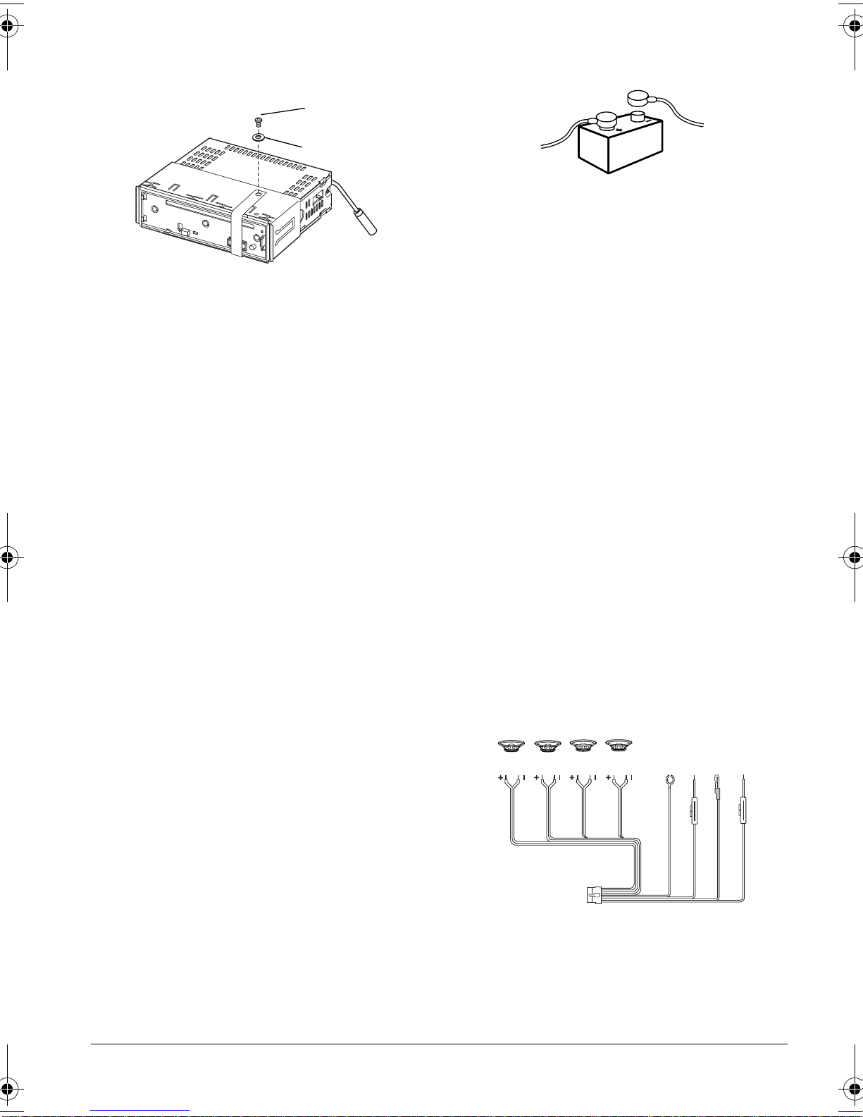
Connecting Ground, Power,
and Optional Components
Follow these steps to connect the har-
ness with the 14-pin connector to
ground, primary and memory backup
power, and optional components.
1. Disconnect the cable from your
vehicle’s negative (–) battery termi-
nal.
2. Connect the black GROUND (–) wire
to a chassis ground, such as a metal
screw attached to a metal part of the
vehicle’s frame. Be sure that the
screw is not insulated from the
chassis by a plastic part.
3. Connect the red +12V TO IGNITION
power wire (with in-line fuse holder)
to a point in your vehicle’s fuse
block that has power only when you
turn the vehicle’s key to either the
accessory (ACC) or START posi-
tion. This connection turns on the
stereo when you turn on the ignition
or turn the key to ACC, and turns off
the stereo when you turn off the igni-
tion. This prevents your vehicle’s
battery from being drained if you
leave the stereo on when you turn
off the ignition.
4. Connect the yellow +12V TO BAT-
TERY wire (with in-line fuse holder)
to your vehicle battery’s positive (+)
terminal or to a point in your vehi-
cle’s fuse block that provides a con-
tinuous source of 12 volts. This
connection provides power for the
stereo’s components (such as the
stereo), and continuous power for
the stereo’s memory when the igni-
tion is turned off.
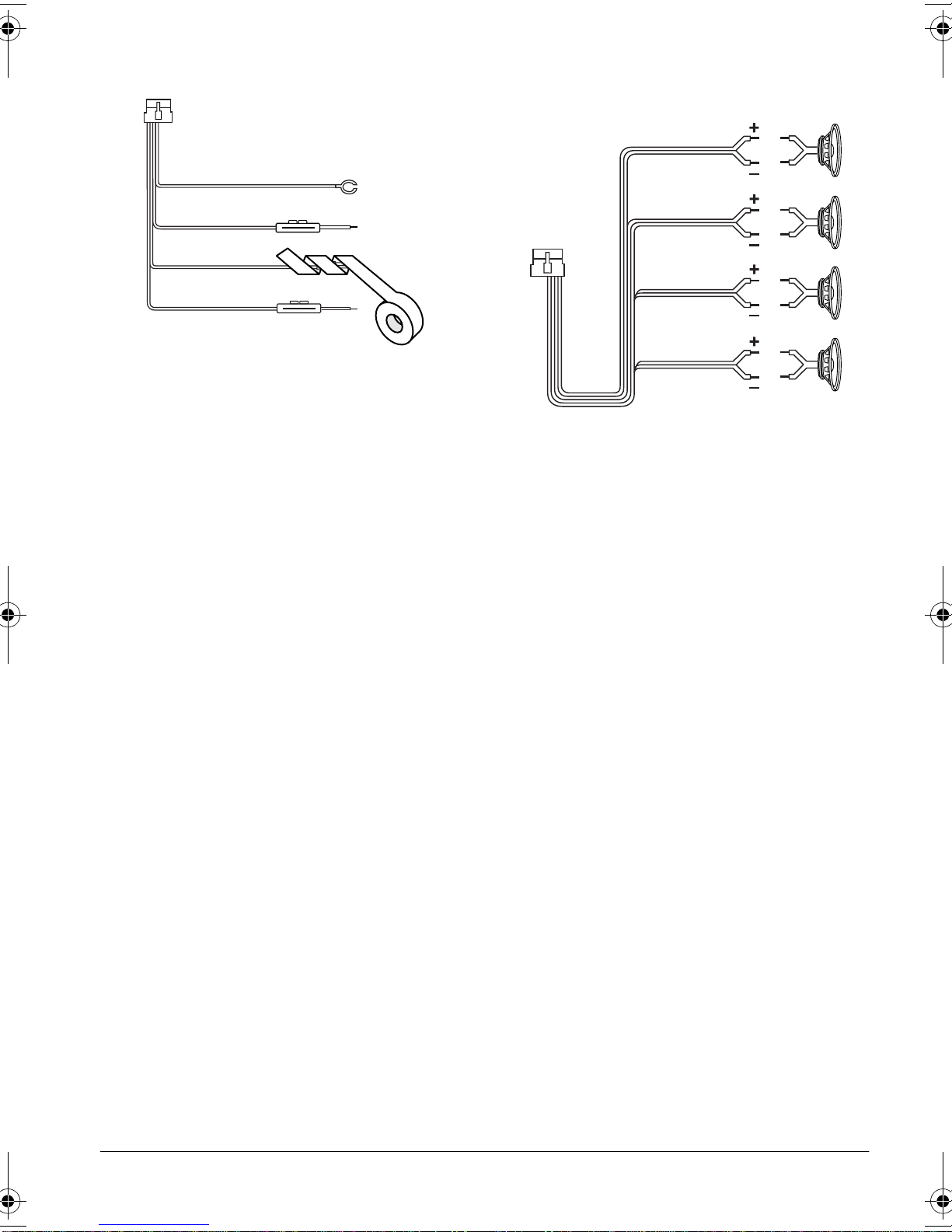
5. Connect the blue/white AMP
REMOTE TURN ON 500mA MAX wire
to any optional equipment, designed
to run from a switched source, that
you want the stereo to turn on and
off (such as a booster or a power
antenna). Cut the loop at the end
and strip about 1/2inch of insulation
for connection.
Note: This wire does not provide
power to the components. It simply
turns them on or off. If you do not
Black GROUND (–)
Red +12V TO IGNITION
Blue/White AMP
REMOTE TURN ON 500mA MAX
Yellow +12V TO BATTERY
12-2157.fm Page 8 Wednesday, March 1, 2000 7:42 AM