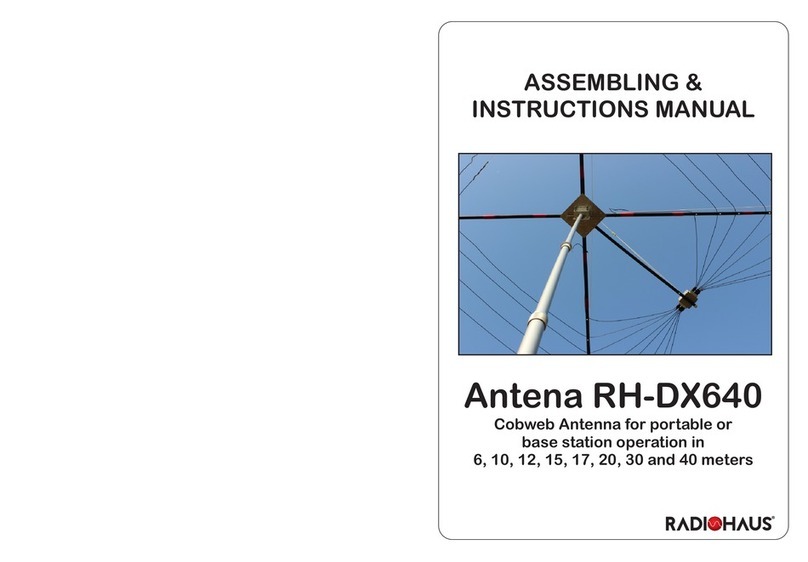
RADIOHAUS SPIDERDXMAN RH-DX1020 User manual

RH-DX1020
Portable Antenna 10, 12 15, 17, 20m
ASSEMBLY INSTRUCTIONS

Thank you for choosing the SPIDERDXMAN RH-DX1020
Antenna, a Cobweb antenna for portable use in the 10, 12, 15, 17 and 20
meter bands. This antenna was developed considering its eciency and
durability of the materials. It is ideal for hamradio operators that have
problems with space and it’s great for using in portable operations.
ATTENTION
• Do not handle or install your RH-DX1020 antenna
near electrical areas
• Always use protective equipment for installation in
height
• Do not touch the antenna when the radio is
transmitting
• Wear gloves to handle ber tubes, since small
particles can cause skin irritation
TOOLS / ACCESSORIES REQUIRED
(not supplied)
• Small pliers
• Wrench
• Silicone rubber
• 50 Ohms Coaxial Cable
• Mast, tripod, mounting hardware
03

1) IDENTIFICATION OF THE PARTS OF YOUR ANTENNA
A B C D
E
F
G
H
A) Mast / Distribution Box Part
B) 4 Pieces Fiberglass tubes with a
nylon cable clamp
C) 4 Pieces Fiberglass tubes with
three nylon cable clamps
D) 2 Pieces Small Fiberglass Tubes
E) 1 Aluminum plate with central axis
clamps
F) 1 Aluminum plate with clamps for
xing the mast
G) 16 bolts / 32 washers / 16 buttery
nuts
H) 10 Nylon cable glands
I) Rope for mooring
04

A
C
B
D
F
B
D
E
C
05

2) ASSEMBLY
2.1) Take the aluminum plate Eand the two tubes D. (Photo 01)
2.2) Position each of the tubes Don one side of the plate E, so that the red marks
match the clamps. Note that the tubes should form a cross and two clamps will
be free for later use. Using a suitable wrench, secure the tubes until rm. (Photo
02) Do not overtighten!
2.3) Insert the tube Bat each end of the four tubes D. Make sure that the drilling
matches. (Photo 03)
2.4) Take 8 screws and t a washer into each of them. Thread the bolts through
the 8 xing holes (two holes in each tube) and insert another washer on the other
side. Secure each screw with a wing nut. (Photo 04)
01 02
03 04
06

Note that the nylon tab should be positioned toward the outside of the assembly.
2.5) In the same way as with tubes B, mount a tube Con each end so that the
plastic cap is positioned on the outside. That way you will have an X-shaped set
that will be the structure of your antenna.
2.6) Take tube A and loosen the elastics that are holding the elements (wires) of
the antenna. Pick up the aluminum foil F. Note that it has 4 clamps, two small
and two larger ones. Insert the tip of tube Ainto the smaller clamps and tighten
slightly. Let it pass a little way until there are a few inches of tube on the end.
2.7) Position tube Aso that the label faces the top of the antenna when the
assembly is complete. Insert the end of tube Ainto the tabs of plate E (the one
you mounted tube X) so that one plate is perpendicular to another. (Photo 05)
The larger clamps will be used to attach the entire assembly to the antenna mast.
05
06
07

2.9) At each end of each wire, insert one of the 10 nylon cable glands. (Photos
07, 08 and 09) Twist the cable press to give pressure and prevent the cable from
escaping. Note that the tips of each antenna element are folded and glued with
electrical tape. Do not remove the insulation tape unless you want to make some
adjustments to your antenna as explained below. Keep the insulation tape and
secure the cable gland over the top.
2.10) Using the nylon rope, tie the ends of each element of the antenna. (Photo
10) If you prefer, you can use nylon cable ties instead of the nylon rope.
2.11) Connect an RG-58 or RG-213 (not supplied) coaxial cable to the antenna
terminal in the footage required to reach your radio. (Photo 11)
2.12) Apply silicone rubber (not supplied) to the screws and onto the coaxial
connector to protect from moisture and water.
2.13) Attach the antenna in a tube or mast and climb to a minimum height of 3
meters (10 ft) from the ground or roof.
07 08
09 10
08

3) ADJUSTMENT
Your RH-DX1020 antenna is already set and centered for the lowest SWR at the
following approximate frequencies:
20m - 14,150kHz
17m - 18,100kHz
15m - 21,200kHz
12m - 24,950kHz
10m - 28,400kHz
In all bands, at the center frequency a very low SWR is obtained, with an increase
of SWR for the ends of each band. Modernt radios with automatic antenna
couplers will easily compensate for this higher SWR.
But if you want to make your antenna more optimized for a specic segment
(for the CW sub-band, for example), you can ne-tune your antenna. Note that
this adjustment is critical and should be done with great patience. In the
case of 17-meter and 12-meter bands whose operating range is only 100kHz, no
adjustment is required since minimum SWR is obtained over the entire range.
In the case of the 20, 15 and 10 meter bands, you can ne-tune as described
below:
• SWR adjustment is achieved at the end of each element. Notice that the tips
are bent and that is where you get the variation of the resonant frequency and the
SWR adjustment;
• First mount your antenna as you received it without removing the red tape from
the tips. After mounting, check SWR on all bands using an antenna analyzer or
your own radio;
• If you nd it necessary to ne-tune the antenna to pick up a certain sub-band,
remove the red tape from the two ends of the track you want to adjust. See
picture 12 for each element;
• Example: If you have measured SWR of 1:1 at 21,200kHz and want SWR at
09

21,050kHz (CW subband), remove the tape and INCREASE the length of the
antenna. This adjustment is critical, so you will have to increase only about 5mm
(1/4”) on each side, reassemble the antenna and give the SWR. If you want the
SWR to be lower at a higher frequency, SHORTEN the antenna’s length. Note
that this operation requires a lot of patience until you get the desired result.
• Having obtained the ideal resonant frequency, fasten the tip of each element
using the cable gland.
5) SPECIFICATIONS
• Cobweb antenna
• Omni-directional (receives and transmits to all sides, no rotor required)
• Impedance: 50 Ohms
• Maximum power: 300 Watts
• Operates on 20, 17, 15, 12 and 10 meters
• Fiberglass elements
• Horizontal polarization
• Water-proof distribution box
• It occupies an area of only 260 x 260cm (approx. 100”)
• Light and compact
• Weight: 7 kg (15.4 lb)
• Fixing in measuring tube or mast 1 ¼ to 2 ¼ “
• Usable even when mounted only 3 meters (10 ft) from the ground
• Can be mounted on a tripod and mast for greater portability
11 12
10

WARRANTY TERM
This product is guaranteed by RADIOHAUS COMÉRCIO E
TECNOLOGIA DE PRODUTOS ELETRÔNICOS LTDA. for
the period of 01 (one) year from the date of acquisition. This warranty
covers defects and materials used in manufacturing.
The warranty does not cover defects caused by misuse or misuse of
the product.
SERIAL NUMBER: _____________
UNIT’S TEST RESULTS:
20m OK
17m OK
15m OK
12m OK
10m OK
Watch the assembly instructions video on our Youtube channel:
Radiohaus Radiocomunicação
11

Rua Candelária, 672 | Centro
Indaiatuba, SP | 13.330-180 | Brazil
www.radiohaus.com.br
Table of contents
Other RADIOHAUS Antenna manuals
Popular Antenna manuals by other brands

ZeroFive Antennas
ZeroFive Antennas 43 FOOT 10 THROUGH 160 METERMULTIBAND... Installation notes

Phonocar
Phonocar SPORT LIFE VM830 instruction manual

Alpha Antenna
Alpha Antenna Alpha Loop operating manual

Fiamm
Fiamm SM21 Installation and user guide

iNetVu
iNetVu 1500 installation manual

A.H. Systems
A.H. Systems AK-40G Operation manual