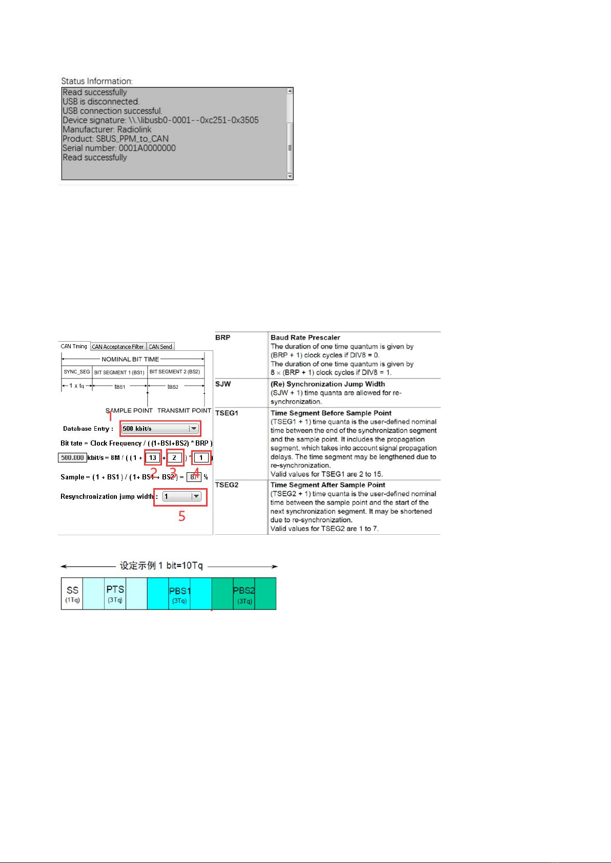
RadioLink RTC8 User manual

RTC8
SBUS/PPM to CAN Protocol Encoder

1
Contents
Chapter 1. Overview ...................................................................................2
Chapter 2. Specifications ........................................................................... 3
Chapter 3. Main Functions ......................................................................... 3
Chapter 4. Driver installation ......................................................................4
Chapter 5. Firmware update ...................................................................... 5
Chapter 6. SBUS/PPM to CAN Explorer ................................................... 6

2
Chapter 1. Overview
1. CAN receive/send interface:
1Used to send and receive CAN data.
2Working baud rate range is 5Kbit/s ~1Mbit/s.
2. Termination resistor 120Ω
The short-circuit jumper cap can absorb signal reflection and echo.
3. Firmware update button
Press and hold the button, then connect the encoder to the computer via USB to enter the
firmware update mode.
4. Power Indicator
Lights up in green after the encoder is powered on.
5. USB connector
1Connect with computer for parameter adjustment and data observation.
2Update the firmware after connecting with the computer.
6. SBUS/PPM input
1SBUS signal input
2PPM signal input
7. Communication status indicator
1When the SBUS signal is input, the blue light flashes 2 times and goes out.
2When the PPM signal is input, the blue light flashes 3 times and goes out.
3When receiving valid CAN data (unshielded ID data) the red light flashes 2 times and
goes out.

3
Chapter 2. Specifications
1. The PC interface conforms to the specification of USB2.0 full-speed interface and is compatible
with USB1.1 and USB3.0.
2. Integrate 1 CAN-BUS interface, and use plug-in terminal wiring method
3. Conform to IOS/DIS 11898 specification
4. CAN-BUS communication baud rate can be freely programmed between 5Kbps~1Mbps
5. Powered by USB/5-15V
6. The received data flow rate is up to 100fps
7. Support Windows 7, 8, 9, 10 and other Windows systems
8. Support SBUS_PPM_TO_CAN test software
9. Support SBUS and PPM signal analysis
Chapter 3. Main Functions
1. Data receiving function
2. Received data display function
3. Data clearing function
4. Filter function
5. Advanced shielding function
6. Data sending function
7. SBUS/PPM signal to CAN signal

4
Chapter 4. Driver installation
1. Use a USB cable to connect the SBUS/PPM to CAN Protocol encoder to the computer.
2. After the successful connection, there will be a new COM port in computer device manager.

5
Chapter 5. Firmware update
1. Press and hold the firmware update button(do not supply power to the encoder). Then connect
the encoder to the computer via USB, the blue light will start to flash. Release the firmware update
button.
2. The computer pops up a window asking whether the U disk needs to be formatted, and you can
directly close the window.
3. Open the firmware upgrade software.
(1) Select the disk that just popped up.
(2) Select the firmware to be updated.
(3) Write the program, and it will pop up “Write Successful”.
(4) Unplug and re-insert the USB to confirm whether the upgrade is successful.
Note: If the blue light is on and the red light flashes quickly after power-on again, the firmware is
abnormal. Please confirm that the firmware is correct, and then repeat the above update
operation.

6
Chapter 6. SBUS/PPM to CAN Explorer
1. Status information display
(1) CAN:
Display currently received CAN data (after filtering ID).
(2) SBUS:
If there is an SBUS signal input, the SBUS channel data will be displayed.
(3) PPM:
If there is a PPM signal input, the PPM channel data will be displayed.

7
2. Debug/Status information
3. Parameter configuration
Notice!
①Each time the device is connected, the parameters will be automatically obtained once and sent
to the computer.
②All parameters must be written after modification. Click "Optimset" in the lower right corner,
otherwise the parameters will not be set successfully.
(1) CAN Timing
①Preset baud rate selection: After selection, BS1, BS2, BRP, and SJW parameters will be
automatically set. When the preset value does not meet the requirements, parameters of BS1,
BS2, BRP, and SJW can be manually adjusted according to the actual situation.
②BS1(TSEG1): Bit segment 1
③BS2(TSEG1): Bit segment 2
④BRP: The duration of one time quantum
⑤SJW: (Re)synchronization jump width (The larger the value is set, the larger the baud rate error
is allowed.)

8
Note:
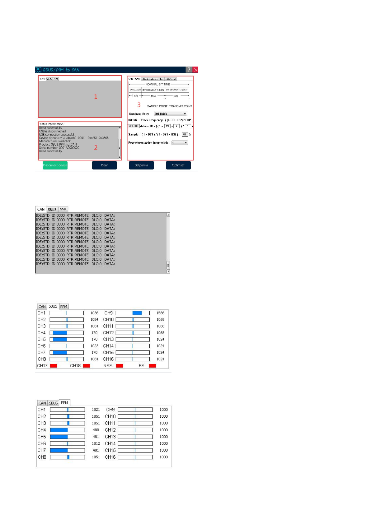
①The synchronization segment is always 1.
②PTS and BS1 have been merged, so the width of BS1 is equal to the width of PTS+BS1.
③Sample: Automatically calculate sampling points according to BS1 and BS2.
Configuration references:
https://blog.csdn.net/piaolingyekong/article/details/124276670
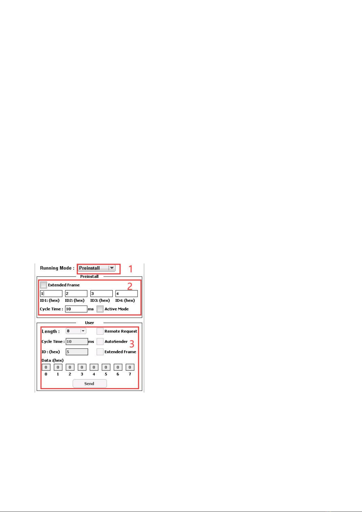
(2) CAN Acceptance Filter
①Running Mode
1. Preinstall: Only receive data matching the 5 IDs of the preset configuration.
(1) Respond after receiving Get 32byte ID, and then send 32 data continuously.
(16 channels, 2 bytes per channel)
(2) Respond after receiving Get 8byte_1 ID, and send 8 data.
(1-4 channels, 2 bytes per channel)
(3) Respond after receiving Get 8byte_2 ID, and send 8 data.
(5-8 channels, 2 bytes per channel)
(4) Respond after receiving the Get 8byte_3 ID, and send 8 data.
(9-12 channels, 2 bytes per channel)
(5) Respond after receiving Get 8byte_4 ID, and send 8 data.
(13-16 channels, 2 bytes per channel)
2. User: Receive data according to the configuration of (match ID) and (mask ID). Only reply.
No additional data is sent.
3. Silent: The working mode ID data before selecting the Silent mode can be received, but it
will not send a response signal.
Note: Only remote frame data is received in this mode.
②ID Mode:
(1) Standard(Standard ID) , with ID range of 0-7FF
(2) Extended(Extended ID), with ID range of 0-1FFFFFFF

9
Note: It is prohibited that all 7 bits are recessive. (Prohibited setting: ID=1111111XXXX)
③Default Values
(1) Click and all parameters on this page will be restored.
④Preset ID
(1) The ID that receives the channel data (Refer to Preinstall).
⑤User Filter ID setting
If you only want to receive the standard frame whose CAN ID is 0x317, the setting method is
as follows:
Filter ID: Set to the binary bit 011 0001 0111, corresponding to 317.
Filter Mask ID: Set to the binary bit 111 1111 1111, corresponding to 1FFFFFFF
If you want to receive standard frames whose CAN ID is 0x310 to 0x317, the setting method
is as follows:
The meaning of each bit in Filter Mask ID:
(1) Bit x is set to 1, and the bit x of the received ID must be consistent with the bit x of the Filter
ID, otherwise it will be ignored.
(2) Bit x is set to 0, regardless of whether the bit x of the received ID matches or not, as long
as all the bits of 1 match, the data will be received and responded. Assuming that the Filter Mask
ID is set to 0, all messages will be received and responded.
(3) CAN Send
①Running Mode: (Consistent with CAN Acceptance Filter)
②Preset mode parameters:
(1) With Extended Frame not ticked, the ID range can be set from 0 to 7FF
(2) With Extended Frame ticked, the ID range can be set from 0 to 1FFFFFFF
Note: It is prohibited that all 7 bits are recessive. (Prohibited setting: ID=1111111XXXX)
(3) ID1: ID that sending data of channel 1-4

10
(4) ID2: ID that sending data of channel 5-8
(5) ID3: ID that sending data of channel 9-12
(6) ID4: ID that sending data of channel 13-16
(7) Cycle Time: The cycle of actively sending channel data
(8) Active Mode: Active sending mode. When Active Mode is ticked, there is no need to send
the command to obtain data to the SBUS/PPM to CAN Protocol encoder, and the device will
periodically send channel data to the CAN bus at the time set by Cycle Time.
③User Mode Parameters
(1) Length: User-defined data sending length
(2) Remote Request
(3) Cycle Time: The cycle of automatically sending channel data
(4) AutoSender: Automatic sending mode. When AutoSender is ticked, the device will
periodically send the set user data to the CAN bus at the time set by Cycle Time.
(5) ID: ID of sent data
(6) With Extended Frame not ticked, the ID range can be set from 0 to 7FF
(7) With Extended Frame ticked, the ID range can be set from 0 to 1FFFFFFF
Note: It is prohibited that all 7 bits are recessive. (Prohibited setting: ID=1111111XXXX)
(8) Data: The data to be sent
(9) Send: Send data key. Data is sent every time it is clicked.
Table of contents