Radwin Transportation FiberinMotion Quick reference guide

DEPLOYMENTGUIDE
TRANSPORTATIONFIBERINMOTION
BROADBANDTRAINTOGROUNDCOMMUNICATION
Release4.5.10

FinMDeploymentGuide Release4.5.10 i
TableofContents
Chapter1:Introduction
1.1ScopeofthisDocument ...................................................................................................... 1‐1
1.2TransportationFiberinMotionOverview ............................................................................ 1‐1
1.2.1MajorComponents...................................................................................................... 1‐2
TBS (Transportation Base Station) units...............................................................1‐3
TBS antennas.....................................................................................................1‐3
PoEs..................................................................................................................1‐3
TMUs (Transportation Mobile Units).....................................................................1‐4
TMU antennas....................................................................................................1‐4
ISUs..................................................................................................................1‐4
OSUs.................................................................................................................1‐5
1.2.2Accessories .................................................................................................................. 1‐5
1.2.3ManagementandConfigurationTools ....................................................................... 1‐5
RADWIN Configurator tool ..................................................................................1‐5
RADWIN Air Link Performance Monitoring tool......................................................1‐5
1.3Applications......................................................................................................................... 1‐6
1.3.1Operational ................................................................................................................. 1‐6
1.3.2PassengerServices ...................................................................................................... 1‐6
1.4Features............................................................................................................................... 1‐6
1.4.1General........................................................................................................................ 1‐6
1.4.2MobilityCapabilities.................................................................................................... 1‐6
1.4.3OnboardMobileUnits ................................................................................................. 1‐6
1.5DocumentNotifications ...................................................................................................... 1‐7
Chapter2:SiteInstallation
2.1ScopeofThisChapter.......................................................................................................... 2‐1
2.2Wayside............................................................................................................................... 2‐1
2.2.1Overview ..................................................................................................................... 2‐1
General Guidelines .............................................................................................2‐1
Power................................................................................................................2‐1
Minimum Recommended Distances......................................................................2‐1
General Mounting Arrangement...........................................................................2‐2
2.2.2TBSMounting.............................................................................................................. 2‐4
TBS Mounting on a vertical pole ..........................................................................2‐6
TBS mounting on a horizontal pole......................................................................2‐9
TBS mounting on a wall....................................................................................2‐13
2.2.3PoEDevicesfortheTBS ............................................................................................. 2‐16
2.2.4TBSAntennas ............................................................................................................ 2‐17
TBS Antenna Mounting on a Vertical Pole...........................................................2‐18
TBS Antenna Mounting on a Horizontal Pole.......................................................2‐21
TBS Antenna Mounting on a Wall ......................................................................2‐22
TBS Antenna Mounting Kit Adaptor....................................................................2‐22
2.2.5TBSExternalConnections .......................................................................................... 2‐25
2.2.6SynchronizationUnits................................................................................................ 2‐25
Indoor Synchronization Unit (ISU) .....................................................................2‐25
Outdoor Synchronization Unit (OSU)..................................................................2‐26
2.2.7ExternalGPSAntenna ............................................................................................... 2‐27
2.2.8LightningProtectionUnit(LPU)................................................................................. 2‐28
2.2.9Waterproofing........................................................................................................... 2‐31
2.3On‐board ...........................................................................................................................2‐33
2.3.1Overview ................................................................................................................... 2‐33
General Guidelines ...........................................................................................2‐33

FinMDeploymentGuide Release4.5.10 ii
Power..............................................................................................................2‐33
General Mounting Arrangement.........................................................................2‐33
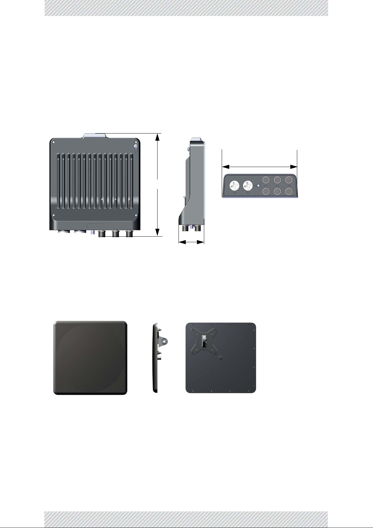
2.3.2TMUMounting.......................................................................................................... 2‐33
Mounting on a wall...........................................................................................2‐43
TMU - External Connections..............................................................................2‐43
2.3.3PoEDevicesfortheTMU ........................................................................................... 2‐43
2.3.4TMUAntennas .......................................................................................................... 2‐44
2.3.5TMUExternalConnections ........................................................................................ 2‐47
2.4Grounding.......................................................................................................................... 2‐47
TBS and OSU...................................................................................................2‐47
TMU................................................................................................................2‐48
FinM PoE .........................................................................................................2‐48
External PoE ....................................................................................................2‐49
ISU .................................................................................................................2‐50
Antennas.........................................................................................................2‐50
Chapter3:NetworkGuidelines
3.1ScopeofThisChapter.......................................................................................................... 3‐1
3.2Overview ............................................................................................................................. 3‐1
3.3WaysideNetwork................................................................................................................ 3‐1
3.4On‐boardNetwork .............................................................................................................. 3‐3
3.5On‐boardPhysicalConnectivity .......................................................................................... 3‐4
3.6WaysideCoreRouter .......................................................................................................... 3‐5
3.7BasicIPSchemeandDataFlowPath................................................................................... 3‐5
3.8RecommendedVLANAssignment....................................................................................... 3‐7
3.9InterBaseHandover(IBHO)UpdateMessage .................................................................... 3‐9
3.10IntraTrainHandover(ITHO)UpdateMessage................................................................ 3‐12
Chapter4:ConfiguringtheRadioNetwork
4.1ScopeofThisChapter.......................................................................................................... 4‐1
4.2ConnectingtotheUnits ...................................................................................................... 4‐1
4.3AbouttheConfiguratorTool ............................................................................................... 4‐1
4.3.1MethodofOperation .................................................................................................. 4‐2
4.4UsingtheConfiguratorTool ................................................................................................ 4‐2
4.4.1MainTab ..................................................................................................................... 4‐2
4.4.2ProjectTab .................................................................................................................. 4‐5
Upper Table.......................................................................................................4‐5
Lower Table: Quality of Service (QoS) Options .....................................................4‐9
4.4.3LineTab ..................................................................................................................... 4‐12
4.4.4TowersTab ................................................................................................................ 4‐15
4.4.5TrainTab ................................................................................................................... 4‐17
4.5InterferenceMitigationforCo‐channelNeighbors........................................................... 4‐17
4.5.1BasicSituation........................................................................................................... 4‐18
4.5.2NecessaryPre‐Conditions.......................................................................................... 4‐18
Activation Conditions........................................................................................4‐19
De-Activation Conditions...................................................................................4‐19
4.5.3MethodofOperation ................................................................................................ 4‐20
4.5.4ConfiguringtheCo‐ChannelNeighborInterferenceMitigationOption .................... 4‐21
4.6ConfiguringNetworkUnits................................................................................................ 4‐25
Configuring an Individual Unit:..........................................................................4‐25
Configuring Many Units at Once:.......................................................................4‐25
4.6.1ConfiguringTransportationBaseStations(TBSs)...................................................... 4‐25
To re-configure a unit that is already installed:...................................................4‐26
4.6.2ConfiguringTransportationMobileUnits(TMUs)..................................................... 4‐27
To re-configure a unit that is already installed in the field: ..................................4‐28
4.6.3ConfiguringIndoorSynchronizationUnits(ISUs) ...................................................... 4‐29
To re-configure a unit that is already installed in the field: ..................................4‐30

FinMDeploymentGuide Release4.5.10 iii
4.7ConfiguratorMessages ..................................................................................................... 4‐31
AppendixA:AntennaGuidelines
A.1ForDeploymentinUS/Canada............................................................................................ A‐1
AppendixC:RevisionHistory

FinMDeploymentGuide Release4.5.10 iv

FinMDeploymentGuide Release4.5.10 1‐1
Chapter1:Introduction
1.1ScopeofthisDocument
ThispublicationshowshowtoinstallandoperateRADWIN’sTransportationFiberinMotion
(FiberinMotionorFinM)solution.
Thispublicationisaddressedprimarilytosystemintegratorsaswellasinstallingtechnicians.
1.2TransportationFiberinMotionOverview
TransportationFiberinMotionisatrain‐to‐waysidecommunicationssolutionthatensures
continuoushigh‐speedwirelessconnectivitybetweentherollingstock,thetracksandcontrol
center.
TheTransportationFiberinMotionsystemconsistsofpowerfulbasestationsdeployedalong
thetracksthatconnecttomobileunitsinstalledonboardtherollingstock.Thesolution
operatesinchallengingoutdoorconditionsandundergroundtunnels.

FinMDeploymentGuide Release4.5.10 1‐2
TransportationFiberinMotionOverview Introduction
Figure1‐1:FiberinMotionOverview
AFiberinMotionsolutionworksasfollows:
•TBS(TransportationBaseStation)unitsareinstalledonpolesorwallseitheroutdoorsor
inatunnel,andareequippedwithantennas(usually4),
•TheTBSunitscommunicatewiththebackhaulnetworkviaaPoEdeviceorfiber,
•TheTBSunitstransmitto/receivefromTMUs(TransportationMobileUnits)installedon
boardrollingstock(alsoequippedwithantennasfortheTMUs),andlocatedwithinthe
beamoftheTBSantennas,
•TheTMUradios,alsopoweredbyPoEdevices,providecommunicationconnectionsfor
on‐boardequipmentsuchasroutersandWiFidevices.
•IndoorSynchronizationUnit/OutdoorSynchronizationUnits(ISU/OSU)synchronizethe
transmissionofbelowgroundTBSunits.
TBS
Antennas
Pole/Wall
TMUs
Rollingstock
PoE
ISU/OSU
StationSwitch Coreswitch Network
&Backhaul

FinMDeploymentGuide Release4.5.10 1‐3
MajorComponents Introduction
1.2.1MajorComponents
ThemajorcomponentsoftheTransportationFiberinMotionsolutionareshownbelow:
TBS(TransportationBaseStation)units
TBSunitscommunicatewiththebackhaulnetworkviaaPoEdeviceorfiber,andtransmitto/
receivefromTMUs(TransportationMobileUnits)installedonboardrollingstock.
TBSantennas
Althoughtherearemanydifferenttypesofantennas(seeAppendixA,AntennaGuidelinesfor
alistofpermittedantennas),werecommendusingflatantennasliketheoneshownhere,
availablefromRADWIN:
Figure1‐2:TBSunit
Figure1‐3:TBSantenna
280mm
75mm
250mm

FinMDeploymentGuide Release4.5.10 1‐4
MajorComponents Introduction
PoEs
Power‐over‐ethernetdevicesareusedtosupplybothpowerandnetworkcommunicationsto
theTBS,TMU,andOSUs.UseonlyPoEsrecommendedbyRADWIN.Inaddition,theTMUcan
besuppliedfromanalternativePoE,asshown.
WhenworkingwiththeTMU,notethataspecialPoE‐TMUcablemustbeused.
TMUs(TransportationMobileUnits)
TMUradios,alsopoweredbyPoEdevices,transmitto/receivefromTBSsinstalledonwayside
polesorwalls,andprovidecommunicationconnectionsforon‐boardequipmentsuchas
routersandWiFidevices.
OutdoorPoE IndoorPoE PoEfortheTMU
Figure1‐4:PoEUnits
Figure1‐5:TMUradio
275mm
40mm
230mm

FinMDeploymentGuide Release4.5.10 1‐5
MajorComponents Introduction
TMUantennas
Useshark‐finantennas,installedontheroofoftherollingstock(seeAppendixA,Antenna
Guidelinesforalistofpermittedantennas):
Figure1‐6:Shark‐finantennaforTMU
ISUs
IndoorSynchronizationUnitsareusedtosynchronizeTBStransmissions.TheISUsare
installedintunnels.
Figure1‐7:IndoorSynchronizationUnit

FinMDeploymentGuide Release4.5.10 1‐6
Accessories Introduction
OSUs
OutdoorSynchronizationUnitsareusedtosynchronizeTBStransmissions.TheOSUsare
basedonthesamehardwarecasingastheTBS,andareinstalledinoutdoorlocations.
Figure1‐8:OutdoorSynchronizationUnit
1.2.2Accessories
Youwillalsoneedsomeofthefollowingaccessories:
•Lightningprotectorunit‐forusewithoutdoorproducts
•CAT6cables‐variouslengthsforusewithradiosandPoEdevices
•Groundingcables
•AdditionalmountingkitsfortheantennasandPoEs‐eachantennaandeachexternal
PoEinstalledonapoleneedsamountingkit.
1.2.3ManagementandConfigurationTools
RADWINConfiguratortool
Thistoolallowsyoutocarryoutbulkcommissioningofgroupsofradios,usuallyonatrackby
trackbasis.ItsuseiscoveredinRadioNetworkConfiguration.
RADWINAirLinkPerformanceMonitoringtool
TheAirLinkPerformanceMonitoring(ALPM)toolisanadvancedanalysistoolforRADWIN’s
FiberinMotionproductline.
TheALPMtoolaccumulatesallimportanteventsandinformationrelatedtoeachunitinthe
systemandtothetargettowhichithasalink.

FinMDeploymentGuide Release4.5.10 1‐7
Applications Introduction
1.3Applications
1.3.1Operational
•Real‐timeCCTVtransmission
•Levelcrossingdetection
•Onboardticketing
•Communications‐basedtraincontrol(CBTC)
1.3.2PassengerServices
•High‐speedinternetaccess
•PassengerInformationSystems
•Multimediaentertainment
1.4Features
1.4.1General
»Ethernetconnectivitybetweenbasestationandsubscriberunits
»AdvancedOFDM&MIMO2x2and3x3fornLOSandNLOSperformance
»Enhancedinterferencemitigationcapability
»Inter&intrasitesynctoreduceselfinterference
»Longrangebetweenbasestations
»Frequencybands‐4.9‐5.9GHz
»DedicatedBandwidthensuringSLA&latency
»Lowandconstantlatency–min<3ms,typical4to20ms
»Channelbandwidth–20/40/80MHz
»Regulationssupported‐FCC/IC/WPC/MII/Universal/JapaneseRegulations
1.4.2MobilityCapabilities
»Upto750MbpsperTBS
»Highspeed‐upto300Kmperhour/186milesperhour
»Upto16TMUsperTBS
»RADWINNetworkManagementSystemsupport
»SmartBandwidthManagement(SBM)usingdynamicbandwidthallocationtomaxi‐
mizeserviceproviderthroughputandadheretocustomerSLAs
1.4.3OnboardMobileUnits
»200MbpsaggregatethroughputperTMU

FinMDeploymentGuide Release4.5.10 1‐8
DocumentNotifications Introduction
»SupportscustomerSLAsbyassignmentofdedicatedbandwidthforuplinkanddown‐
linkperTMU,attheTBS
»SeparateuplinkanddownlinkconfigurableMaximumInformationRate(MIR)per
TMU
1.5DocumentNotifications
NotificationsconsistofWarnings,CautionsandNotes.
Warning:riskofdangertopersons.
Caution:riskofdamagetoequipmentorofservicedegradation
•Provideadditionalbackground
•Offerarecommendation
•Remindyouofsomethingthatshouldbekeptinmind

FinMDeploymentGuide Release4.5.10 2‐1
Chapter2:SiteInstallation
2.1ScopeofThisChapter
ThischapterdescribeshowtoinstalltheequipmentfortheTransportationFiberinMotion
solution.
2.2Wayside
TheFiberinMotionsolutionusesmultipleantennastoenableMIMOandDiversitymodes.
Thesolutionreliesonantennaspacing,aswellasdualpolarization/dualslantedantennasto
differentiatetheradiostreams.
2.2.1Overview
GeneralMountingArrangement
TheTBScanbemountedonapoleorawall,togetherwithitsantennas,LPUsandPoEdevice.
ToenablebetterMIMOconditions,theantennasshouldbedividedbetweenverticaland
horizontalpolarizations.Figure 2‐1showsaschematicviewwiththesepolarizations.
•Placethetower/TBSatthelocationdeterminedbythesitesurvey.
•Makesurethereissufficientline‐of‐sighttowardsthetracksegmenttheantennas
willcover
•Makesurethattherearenoobstaclesdirectlyinfrontoftheantennas
•Thelowestantennamustbehigherthanthehighestrailcarontheline

FinMDeploymentGuide Release4.5.10 2‐2
Overview SiteInstallation
Figure2‐1:TBS‐BaseStationmountingwithantennas(outside)

FinMDeploymentGuide Release4.5.10 2‐3
Overview SiteInstallation
Table2‐1:TBS‐BaseStationmountingwithantennas(tunnel)
Power
•UsethePoEtosupplypowertotheTBS
•UsethePoEortheSFPfiberconnectiontoprovideaserviceconnectiontothe
TBS.
•InstalltwoLightningProtectionUnits(LPU):OneclosetotheTBS,andtheother
closetothePoE.
MinimumRecommendedDistances
Therearetwoantennasforeachdirection:Aisforapproachingtrains,andBisfor
recedingtrains(seeFigure 2‐1).Separatetheantennasasmuchaspossible,and
maintainthefollowingminimaldistances:
•Recommendedverticalseparationbetweeneachantennais1.0m.

FinMDeploymentGuide Release4.5.10 2‐4
TBSMounting SiteInstallation
2.2.2TBSMounting
TheTBScanbemountedonaverticalorhorizontalpole,oronawall.
•Verticalpole:seepage 2‐6fordirectionsrelevanttoallsizes.
•Thinpole:seepage 2‐6.
•Mediumpole:seepage 2‐8
•Thickpole:seepage 2‐8
• Horizontalpole:seepage 2‐9fordirectionsrelevanttoallsizes.
•Thinpole:seepage 2‐11.
•Mediumpole:seepage 2‐12
•Thickpole:seepage 2‐13
• Wall:TheTBScanbemountedonawall,seepage 2‐13.
Checkthepackagecontents:
Figure2‐2:TBSmountingkitpackagecontents
Table2‐2:TBSmountingkitpackagecontents
Item
No. Description Quantity
1Baseplate 1
2Poleclamp 1
3HexscrewwithflangeM8x90 2

FinMDeploymentGuide Release4.5.10 2‐5
TBSMounting SiteInstallation
4StandoffsM4x16 4
5AllenscrewsM4x30 4
6Washersforallenscrews 4
Table2‐2:TBSmountingkitpackagecontents(Continued)
Item
No. Description Quantity

FinMDeploymentGuide Release4.5.10 2‐6
TBSMounting SiteInstallation
TBSMountingonaverticalpole
Allsizes
1. Fastenthestandoffstothebaseplateintheholeslabeled“V”asshown:
Figure2‐3:Fastenstandoffstobaseplate(forverticalpole)
2. PlacetheTBSasshownoverthestandoffs,andusingtheAllenscrewsandwashers,fasten
theTBStothebaseplate.
Figure2‐4:FastenTBStobaseplate(forverticalpole)
VerticalPole‐thin
1. Diameter3/4to11/2:BeforeraisingtheTBSonthepole,positionthepoleclampasshown
inthefollowingtwofigures.Donotcompletelytightenthebolts:

FinMDeploymentGuide Release4.5.10 2‐7
TBSMounting SiteInstallation
Thinpole(diameter3/4to11/2):Positionthepoleclampasshowninthefoll owing twofigures,donotcompletelytightenthebolts:
2. PlacethisassemblyonthepolewhereyouwanttomounttheTBS.Onceitisinplace,
rotatethepoleclampasshown,thentightenbothbolts.
Figure2‐5:Thinpole:Fastenclamptobase
plate
Figure2‐6:Thinpole:Donotcompletely
tightenbolts
Figure2‐7:Thinpole:Rotateclamp Figure2‐8:Thinpole:tightenbolts
Other manuals for Transportation FiberinMotion
1
Table of contents
Other Radwin Network Hardware manuals