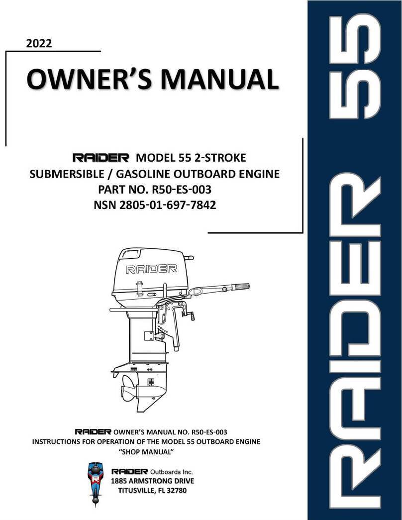
Raider Outboards Raider 40 HP User manual

i

ii
This page intentionally left blank

iii
RAIDEROutboards
MULTI-FUEL SUBMERSIBLE ELECTRIC START OUTBOARD ENGINES
The Raider series of outboard motors are dedicated to the Marine Raiders established by the United
States Marine Corps during WWII and are said by many to be the first United States special operations
force. Handpicked from the elite, these men were given specialized training and the best equipment.
They distinguished themselves during the conduct of clandestine amphibious landings, utilizing small
inflatable boats, operating behind enemy lines in direct support of combat operations in the Central
Pacific and Solomon Islands. Even though the Raiders were disbanded at the close of WWII the need for
specially trained warfighters and the requirements for specialized equipment did not. Today’s Special
Operations Forces (SOF) under the United States Special Operation Command (USSOCOM) are expected
to conduct similar and far more demanding missions, to that end and with those warfighters in mind the
Raider (OBM) is specifically developed for SOF that routinely operate within the often unforgiving, highly
demanding, dynamic maritime environment.
WHO WE ARE
•Raider Outboards, Inc. is a-US owned and operated company based in Central Florida near
Kennedy Space Center, located in the Space Port Commerce Park. We design and produce multi-
fuel, submersible, lightweight outboard motors and associated parts that include a Safety Jet;
transom plates; carts and transportation cages. Our markets include Department of Defense
(DOD), Other Government Agencies (OGA), National and Local Law Enforcements and First
Responder Services, Search & Rescue and commercial/retail.
•The Raider patented Safety Jet can be purchased in a kit which retrofits a propeller drive to a jet
pump system. The Safety Jet was designed to improve safety for swimmers and divers in both
real-world and training situations. The Safety Jet is excellent for “brown water” operations where
search and rescue operations routinely happen in which higher probabilities of striking
submerged objects exist. For coastal or beaching operations in unfamiliar waters it provides
additional protection from rocks or coral easily absorbing hits that could ruin propellers when
moving to and from a beach landing site.
•Raider also provides a series of transom plates that are attached to the transom of the Combat
Rubber Raiding Craft (CRRC). The transom plates have single and dual motor configurations. The
transom plates provide centerline alignment and safety if the motor clamps loosen under
vibration. Specialty items like extended handles, extended fuel hose connections, outboard
motor carts and transportation cages are also available.

iv
WHAT WE ARE ABOUT
Raider Outboards develops, manufactures, and provides technical support services for highly reliable
outboard motors for today’s warfighter. Our designs are field proven, and add capacity and capability to
perform the most difficult and demanding maritime missions. Features include;
•Simple and Robust.
•System Redundancy.
•Minimized Electronics.
•Air droppable.
•Bagless submersion.
•Superior dewatering.
•Leader in horsepower to weight ratio.
•25% better fuel efficiency than any other motor in its class.
•Easy to maintain and troubleshoot.
OUR MISSION
Raider Outboards will provide and deliver the most reliable premium products, hands on training, and
highest quality to the customer and serve as the premier outboard motor company to the U.S. Military;
while honoring those who protect, defend, and support our communities and our country.
Chris Woodruff
Director of Engineering
Raider Outboards Inc.
321-567-2309

v
YOUR RAIDER OUTBOARD MOTOR
a. The Raider R40ES-002 NSN 3H 2805-01-652-3067 outboard motor is designed specifically for and
specially manufactured for the Department of Defense for use as the main propulsion system on
Combat Rubber Raiding Craft (CRRC). The Raider brings additional capability far superior to any
other motor in its class. This motor can be submerged, without bagging, for extended periods
and quickly restarted; operates on multiple fuels; equipped with an electric start feature utilizing
an engine start battery located under the cowling.
b. We would like to emphasize that optimum motor operational performance can only be assured
on the condition that this manual is read through in its entirety and the maintenance routines
described later are followed carefully. Should difficulty arise with the motor, please follow the
troubleshooting procedures listed throughout the specified sections within this manual. For any
other issues, questions, or concerns please call 321-567-2306 or contact
provide you with any assistance required.
OWNER REGISTRATION AND IDENTIFICATION
a. This Raider outboard has been purchased by the Department of Defense. Every motor has been
delivered under Form DD-240 which contains individual Serial Numbers and Raider Outboards
has a record of every motor delivered.
b. Serial Number: In the space provided below, please record the outboard motor's serial number
which is indicated on the starboard side of the cylinder block. The serial number will be needed
in ordering spare parts.
c. Serial Number: _______________________________________________________

vi
LIMITED WARRANTY
a. Raider Outboards Motors are fully guaranteed against defective materials and workmanship for
the period from the date of the Form DD-240 for one year. The limited warranty will not apply to
the normal wear and tear of parts, adjustments, tune-ups, or to any damage caused by:
1.
Use or operation NOT conforming to the instructions described in this owner's manual.
2.
Damaged caused as a result of parachute failure or improper parachute rigging.
3.
Damage, Deterioration, or Corrosion resulting in motor failure due to improper conduct of
Pre and Post Operations Checks. The Raider 40 HP Outboard must be flushed with fresh water
and washed down after use.
4.
Improper dewatering. Damage caused by failure to adhere to the dewatering procedures.
5.
Damage from accidents, collisions, contact with foreign materials, or submersion without
cleaning.
6.
Growth of marine organisms on motor surfaces that exceeds recommended submergibility
times or left in the water between operational periods.
7.
Any other careless use or operation issues. (Battery unplugged when not in use)
8.
Normal deterioration.
b. The limited warranty does not cover maintenance items. The following items are some examples
not covered by the limited warranty.
c. Spark plugs, anodes, trim-tab, propeller, fuel filter, Starter rope, split-pin, bolt/nut washer, wire
cable. Rubber goods: pump impeller. Oil seal, "O"-ring, fuel line, primer bulb, etc., vinyl tube.
d. The limited warranty will cover only your Raider Outboards 40HP and will not cover the craft the
motor is mounted on, the trailer, equipment, or accessories associated with the product.

vii
THIS MANUAL
a. This owner’s manual provides information that is needed for inspection, procedures to prepare
the motor for an operational cycle, preventative maintenance and troubleshooting of the Raider
Outboards 40HP. Additional information about specific systems and parts are described within
the service and parts manuals. These manuals including this one may be found on the Raider
Outboards web site raideroutboards.com and may be downloaded for convenience. Should
additional information be required please call or email customer service department at 321-567-
2306 or TechSupport@raideroutboards.com.
b. For our users we have built the best outboard motor for long term, it is essential for the
maintainer to prepare the outboard prior to the operational period. To ensure this, the
maintenance and service have to be done properly by a service technician with fundamental
knowledge and skills. This manual is utilized so that our operators can always use their outboard
motor with full satisfaction.

viii
CONTENTS
GENERAL INFORMATION..................................................................................................................................................1
Safety Information..................................................................................................................................................1
Notice: Danger/Warning/Caution/Note.................................................................................................................1
Emergency Stop Switch ..........................................................................................................................................2
Raider Maintenance Tool Kit ..................................................................................................................................2
Raider Emergency Tool Kit .....................................................................................................................................3
Capabilities/Features..............................................................................................................................................4
Specifications..........................................................................................................................................................6
Components and Controls......................................................................................................................................8
Fuel Requirements .............................................................................................................................................. 18
Hazardous Material Requirements...................................................................................................................... 20
Break-In ............................................................................................................................................................... 21
STANDARD OPERATING PROCEDURES............................................................................................................................. 22
Pre and Post Operations Checks ......................................................................................................................... 22
Pre-Operations Checks ........................................................................................................................................ 23
Operational Checks.............................................................................................................................................. 26
Post Operations Checks....................................................................................................................................... 28
Motor Mounting.................................................................................................................................................. 29
Propeller Selection .............................................................................................................................................. 30
Starting the Raider 40 HP .................................................................................................................................... 31
Maneuvering ....................................................................................................................................................... 34
Trim Adjustments ................................................................................................................................................ 35
Shallow Water Running/Beaching....................................................................................................................... 37
Dewatering .......................................................................................................................................................... 38
Emergency (Tertiary) Starting ............................................................................................................................. 41
MAINTENANCE REQUIREMENTS..................................................................................................................................... 42
Tach/Hour Meter................................................................................................................................................. 43
Spark Plugs........................................................................................................................................................... 44
Carburetor Tuning ............................................................................................................................................... 46
Timing .................................................................................................................................................................. 48
Cylinder Compression Test.................................................................................................................................. 49

ix
Gear Oil Change................................................................................................................................................... 51
Gearcase Pressure and Vacuum Tests................................................................................................................. 53
TROUBLESHOOTING ..................................................................................................................................................... 54
APPENDICES................................................................................................................................................................ 56
Pre Operations Checklist ..................................................................................................................................... 57
Post Operations Checklist.................................................................................................................................... 61

Raider 40 HP
SECTION 1
Owner’s Manual
General Information
1
GENERAL INFORMATION
SAFETY INFORMATION
As the operator or coxswain of your craft, first and foremost, you are personally responsible for the
safety of the crew, embarked personnel, and any person in the water or in the vicinity of the craft. Safety
is paramount in all operations. Therefore, you should possess thorough knowledge of correct operation
of your craft, its accessories, and the Raider Outboard Motor. This manual details the proper procedures,
correct operation and maintenance of the motor. Additional hands on training courses for both the
operators and technicians are available through Raider.
NOTICE:DANGER/WARNING/CAUTION/NOTE
Before installing, operating or otherwise handling your Raider Outboard Motor, be sure to thoroughly
read and understand this operations section of this manual and carefully follow all of the instructions.
Of particular importance is information preceded by the words "DANGER," "WARNING," "CAUTION," and
"Note." Always pay special attention to such information to ensure safe operation of the outboard motor
at all times.
The following safety statements are found throughout this manual and indicate information which, if
ignored, could result in fatal safety hazards or property damage.
Failure to observe will result in severe personal injury or death, and possibly property damage.
Failure to observe could result in severe personal injury or death, or property damage.
Failure observe could result in personal injury or property damage
This instruction provides special information to facilitate the use or maintenance of the outboard
motor or to clarify important points.

Raider 40 HP
SECTION 1
Owner’s Manual
General Information
2
EMERGENCY STOP SWITCH
The Emergency Stop Switch will stall the outboard motor when the stop switch tether is pulled off. This
stop switch tether can be attached to the operator of the outboard motor to minimize or prevent
injuries from the propeller in case the operator falls overboard. We highly recommend use of the
Emergency Stop Switch tether.
RAIDER MAINTENANCE TOOL KIT
The Raider Maintenance Kit (RMK) is a complete tool
set that is specifically designed and provides
Operators and Field Service Technicians with the
necessary tools to perform routine maintenance
actions or intermediate level motor troubleshooting
and repair to the component level. The tools are
stowed and secured in a waterproof case for ease of
transport and protection from harsh environmental
conditions. For inquiries into purchase of the RMK
please contact Raider at sales@raideroutboards.com
or 321-567-2307 by phone for information.
Accidental activation of the Emergency Stop Switch (such as the tether being pulled out in heavy
seas) could cause passengers to lose their balance and even fall overboard, or it could result in loss
of power in heavy seas, strong currents, or high winds. Loss of control while mooring is another
potential hazard.

Raider 40 HP
SECTION 1
Owner’s Manual
General Information
3
RAIDER EMERGENCY TOOL KIT
Included with each Raider Outboard Motor is a
Raider Emergency Field Kit (EFK). This includes tools
for underway troubleshooting and emergency
repairs and spare parts. The tools and parts provided
are contained inside a small waterproof case
designed for easy stowage and is intended to be
carried onboard the craft as part of the operational
load out. This kit is not inclusive and additional items
may be required based on organizational Standard
Operating Procedures (SOP). The EFK includes the
following items:
Part Number
Qty
Description
SBE110
2
Spark Plug
841140
1
M10 Deep Socket 3/8 Dr
841156
1
M16 Deep Socket 3/8 Dr
841153
1
M13 Deep Socket 3/8 Dr
2292340
1
Stanley 6 way screwdriver
67149
1
Crescent Wrench
375532
1
Pliers
68513
1
3/8 Hex drill socket
63518
1
1800 Weatherproof Pelican Case
400B
7 FT
#5.5 Starter Cord
24002
1
2 oz. tube Corrosion Block Grease

Raider 40 HP
SECTION 1
Owner’s Manual
General Information
4
CAPABILITIES/FEATURES
Multi-fuel
Dependent upon fuel available. The Raider 40 HP is capable of using multiple fuel sources for operation.
Gasoline, is the recommended fuel but should the mission or situation dictate various types of Heavy
Fuel combined with the Raider Additive may be used. Regardless of fuel type utilized for operations there
still exists the requirement for mixing with 2 cycle oil at the ratio of 50:1.
Submersible
Allows for full submersion, in salt water, without bagging to a depth greater than 65ft for periods
exceeding 24 hours.
Dewatering
Upon recovery to the surface fully operational within 10 minutes. Easy instructions for dewatering are
provided affixed to each engine cowling of every outboard motor. Most operators, with practice and
adherence to the provided instructions, restore the motor to operations within two minutes of surfacing.
Skilled operators are able to achieve lite off in as few as 30 seconds.
Air Deployable
When required is capable of being dropped from both fixed wing and rotary aircraft. Battery cutoffs are
available to preserve start battery life in drop packages for over 180 days. Prior to drop, the operator
enables the start battery should expeditious start be required on the drop zone.
Lightweight
Maneuverable through the hatch of a Submarine or mounting when underway. The motor is easily
maneuvered by two personnel through the hatches of ships or submarines by using the installed
reinforced no slip grab handles and rails. The special rail design allows the motor to be stowed in an
upright position of the deck or pallet instead of laying on its side.
Electric Start
Provides fast starting in duress situations and aids in dewatering. The installed Acid Glass Matt Battery
adds the ability to start the motor without the use of the recoil starter. This capability may prove to be
invaluable where starting the motor is not practical via the primary method due to motor damage,
operator injury, or prevailing environmental conditions will not afford such. When used with dewatering
it rapidly expels any water through the decompression valves.

Raider 40 HP
SECTION 1
Owner’s Manual
General Information
5
Tactical Communications Power Interface
Power and charge tactical communications systems. Various types of connectors may be installed per
the requirement of the operator. Power tactical radio systems through battery eliminators, charge cell
phones or even power a spot light.
Bolt on Safety Jet
Prevents injury to personnel from inadvertent contact with the propeller. Moreover, provides increased
reliability during beaching or Search and Rescue applications supporting hurricane relief and emergency
response. Protects crafts propulsion systems when transiting through shallow and flooded areas from
unseen obstructions that when struck would normally render a craft dead in the water.
Transportation Cage and Cart.
Allows for safe secure storage of motor when not in use or being transported over the road or by air.
Raider provides two-part system, consisting of a cart and cage. The cart provides a mobile mount for the
performance of maintenance actions and repairs. For safe secure storage the cart maybe locked into
place inside the Transportation Cage. This provides extra protection when conducting movement via
land or by Military Air ensuring your motor arrives in theater ready for immediate operations.
Engine Cover
Protects motor from prevailing environmental conditions should the need require stowage in less than
ideal conditions or outside. A specially designed breathable material allows moisture to evaporate.
Transom Plates
Provides a means for repetitive, expeditious, safe, and secure mounting of the motor on any marine craft
transom. These plates provide a guide for the stern bracket of the motor that will automatically center
the Raider 40 to the keel (center line) of the craft. Then simply tighten the stern bracket screws.
Twin Motor Mount System
A dual control mounting system that supports two Raider Outboards on the same transom. In
conjunction with the Raider Transom Plate the dual control system can be attached quickly allowing
operation of both steering and throttle control using a single tiller arm. The tiller arm may be extended
for easier movement by adding the tiller extension.

Raider 40 HP
SECTION 1
Owner’s Manual
General Information
6
SPECIFICATIONS
ITEM
RAIDER 40 HP
NSN 3H 2805-01-652-3067
Overall length
38.18 inches (919 mm)
Overall width
13 inches (330.2 mm)
Overall height
49 inches (1245 mm) (Long Shaft)
Weight
148 lbs. (67kg)
Transom length
20.9 in. (530 mm) (Long Shaft)
Engine type
2-Stroke Throttle Body
Piston Displacement
493 cc
Bore and Stroke
2.76 x 2.52 (70 mm x 64 mm)
Number of cylinders
2
W.O.T.
5200 – 5800 rpm
Exhaust System
Through Hub
Cooling System
Water cooling (Rotary rubber impeller)
Ignition System
C.D. ignition
Starting System
Pull Start; Battery; emergency rope start
Intake System
Reed Valve
Lubrication system
Fuels pre-mixed with additives
Cooling system
Forced Water-cooling
Water temperature control
Thermostat (with pressure relief valve)
Ignition System
Flywheel Magneto C.D. Ignition
Gear Reduction Gear Ratio
13:25 1.85
Spark Plug
NBE1H/10 (stainless steel) GAP “.035”
Alternator
12V 280W (Maximum) (13.6 volts regulated)
Battery
Acid Glass Mat (AGM), 12VDC @ 10Ah with 175CCA
Trim Angle
4-24 degrees
Trim Angle settings
6 degrees
Maximum tilt-up angle
75 degrees
Transom board thickness
31-70 mm (1.22 – 2.76 in.)
Maximum steering angle
80 degrees
Gear shift
Dog clutch (F-N-R) – front location
Electric Start
Push button
Throttle Control
Tiller Handle
Fuel Bladder/Tank
Organizational Dependent
Heavy Fuels
50:1 mix, Raider Elixir Additive
Gasoline
50:1 mix
Engine Oil
TC-W3 Synthetic Marine Oil
Gear Oil
Synthetic API GL5, SAE#80 to #90 500 ml (16.89 fl. Oz.)

Raider 40 HP
SECTION 1
Owner’s Manual
General Information
7
1. Tilt Handle
11. Trim Tab/Anode
21. Oil Plug (Upper)
2. Top Cowl
12. Propeller
22. Water Inlet
3. Hook Lever
13. Starter Handle
23. Oil Plug (Lower)
4. Water Check Port
14. Dewatering Lever
24. Emergency Stop Switch
5. Rear Carry Grab Rail
15. Throttle Grip
25. Front Grab Handle
6. Fuel Overboard Tube
16. Throttle Tension Adjust
26. Stern Bracket Anode
7. Water Plug
17. Shift Lever
27. Primer
8. Reverse Lock Lever
18. Stern Bracket Clamp
28. Electric Start
9. Drive Shaft Housing
19. Stern Bracket
29. Fuel Connect
10. Anti Ventilation Plate
20. Thrust Rod

Raider 40 HP
SECTION 1
Owner’s Manual
General Information
8
COMPONENTS AND CONTROLS
Cowling
A removable cover of the outboard motor that provides
protection for the powerhead and components during
operation and storage.
Cowling Latch
A mechanism located on the rear portion of the lower
engine cover that provides a means to secure the
cowling in place.
Cowling Retention Strap
Velcro Straps fixed to the cowling and lower engine
cover that prevent the cowling from dislodging during
air drop, motor submersion, or craft capsize.

Raider 40 HP
SECTION 1
Owner’s Manual
General Information
9
Pull Handle and Cord
T-Handle grip fixed to the leading end of the pull cord of
the recoil starter. Routed through the starter cord
opening of the cowling for operator access. This is the
primary method used to start the motor.
Tiller Arm
Mechanical lever the attaches to the swivel bracket that
allow the operator to steer the craft to port or
starboard. Also provided the mounting structure for the
Throttle Control and Throttle Tension Adjustment.
Throttle Control
Affixed to the end of the Till Arm. Allow the operator to
control the acceleration and deceleration of the motor.
It provides a raised indicator that aligned for ideal
throttle position during motor start.

Raider 40 HP
SECTION 1
Owner’s Manual
General Information
10
Throttle Tension Adjustment
A control located on the inboard side of the Tiller Arm.
Provides adjustable resistance to movement of the
throttle grip and can be set to operator preference.
Forward Carry/Grab Handle
Located on the forward part of the motor. Provides the
operator with a secure means to lift the motor for
movement or mounting.
Carry/Grab Rail
Located around the left, right, and rear of the motor.
Provides a means for the operator to lift the motor for
movement or mounting. Also provides a means for the
motor to me laid down in the upright position. Coated
with a non-slip surface.

Raider 40 HP
SECTION 1
Owner’s Manual
General Information
11
Dewatering Lever
Mechanical lever located on the right side of the motor.
When actuated it opens the Dewatering Valve to expel
bad fuel overboard and by means of a rod and fingers it
opens Decompression Valves on the cylinder head, so
that water may be expelled from the cylinders. Features
a detent position, to allow for hands free operation
while dewatering.
Gear Shifter
Located on the forward section of the lower engine
cover. Three position lever that allows for selection of
forward, neutral, and reverse. Ensure that the throttle is
at idle before placing the motor into gear.
Tachometer/Hour Meter
Displays the total number hours the Raider Outboard
Motor has been operational. A tachometer mode can be
selected by the operator for the purpose monitoring
motor RPM.
This manual suits for next models
1
Table of contents
Other Raider Outboards Outboard Motor manuals