P/N R9340-0104 8 © 2010 RAILWAY EQUIPMENT CO.
REV B
5/11
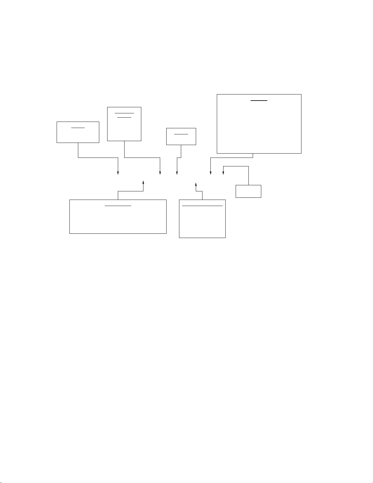
B. STANDARD DUCTWORK
1. HEAT DUCT: The first section of ductwork attached to the main HAB unit.
This duct contains the heaters, fuses, air flow switch and overtemp.
2. FLEX DUCT: Connects the heat duct to the offset duct. It is a section of
flexible duct, enclosed in an insulated sheet metal wrapper.
3. HEAVY DUTY OFFSET DUCT: Connects the flex duct to the tie outlet duct.
This duct provides an 8” offset.
4. TIE OUTLET DUCT: The outlet duct extends under the rails in place of a tie
and directs the airflow to the point nozzles and track ducts. The rail attaches to
the duct using tie plates and E clips. The tie plates are electrically insulated from
the rail using an insulating kit. There are six openings in the top for point nozzles
and track duct nozzles. Refer to the drawing page for the duct layout.
5. TRACK DUCTS: These ducts rest on brackets on the ties and the outlet duct.
They are installed over the track duct nozzles. The track ducts consist of a 5’
point, a 5’ mid, and 10’ sections to complete the desired length.
6. TRACK DUCT NOZZLE: Attaches to the inner two rectangular openings on
the top of the outlet duct. Directs airflow down the length of the switch through
the track ducts.
7. TRACK DUCT NOZZLE ISOLATING KIT: This is an electrically insulating
gasket with insulating washers and hardware to provide isolation between the
nozzles and the outlet duct. Refer to drawing 9278-0027 for proper installation.
8. QUICK CHANGE NOZZLE PLATE: This plate allows for quick removal or
installation of nozzles to the tie duct, by simply loosening of four bolts the nozzle
assembly can be removed or installed.
9. TRACK DUCT SUPPORT BRACKET: These brackets are used to secure the
track duct in position. Refer to drawing 92774.
10. SWITCH POINT NOZZLE: These nozzles direct heated air down the switch
point. They are mounted on the outlet duct. They can be adjusted for proper
airflow direction. Nozzles may be shortened by up to 10” for proper fit.
11. POINT NOZZLE ISOLATING KIT: This is an electrically insulating gasket
with insulating washers and hardware to provide isolation between the nozzles
and the outlet duct. Refer to drawing 9278-0021 for proper installation.