RAKINDA LV3296 Quick setup guide

Integration Guide
LV3296
OEM Scan Engine

Revision History
Version Description Date
V1.0.0 Initial release. October 23, 2015

Table of Contents
Chapter 1 Introduction.......................................................................................................................................1
Overview ..........................................................................................................................................................1
Illumination.......................................................................................................................................................1
Aimer................................................................................................................................................................1
Chapter 2 Installation.........................................................................................................................................2
General Requirements.....................................................................................................................................2
ESD..............................................................................................................................................................2
Dust and Dirt................................................................................................................................................2
Ambient Environment...................................................................................................................................2
Thermal Considerations...............................................................................................................................2
Installation Orientation.................................................................................................................................2
Optics ...............................................................................................................................................................4
Window Placement......................................................................................................................................4
Window Material and Color..........................................................................................................................4
Scratch Resistance and Coating .................................................................................................................4
Window Size ................................................................................................................................................4
Ambient Light...............................................................................................................................................6
Eye Safety....................................................................................................................................................6
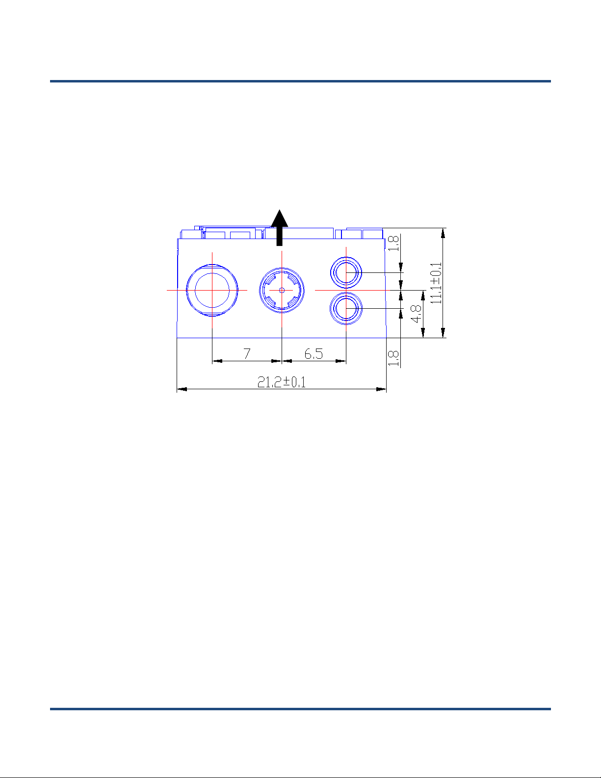
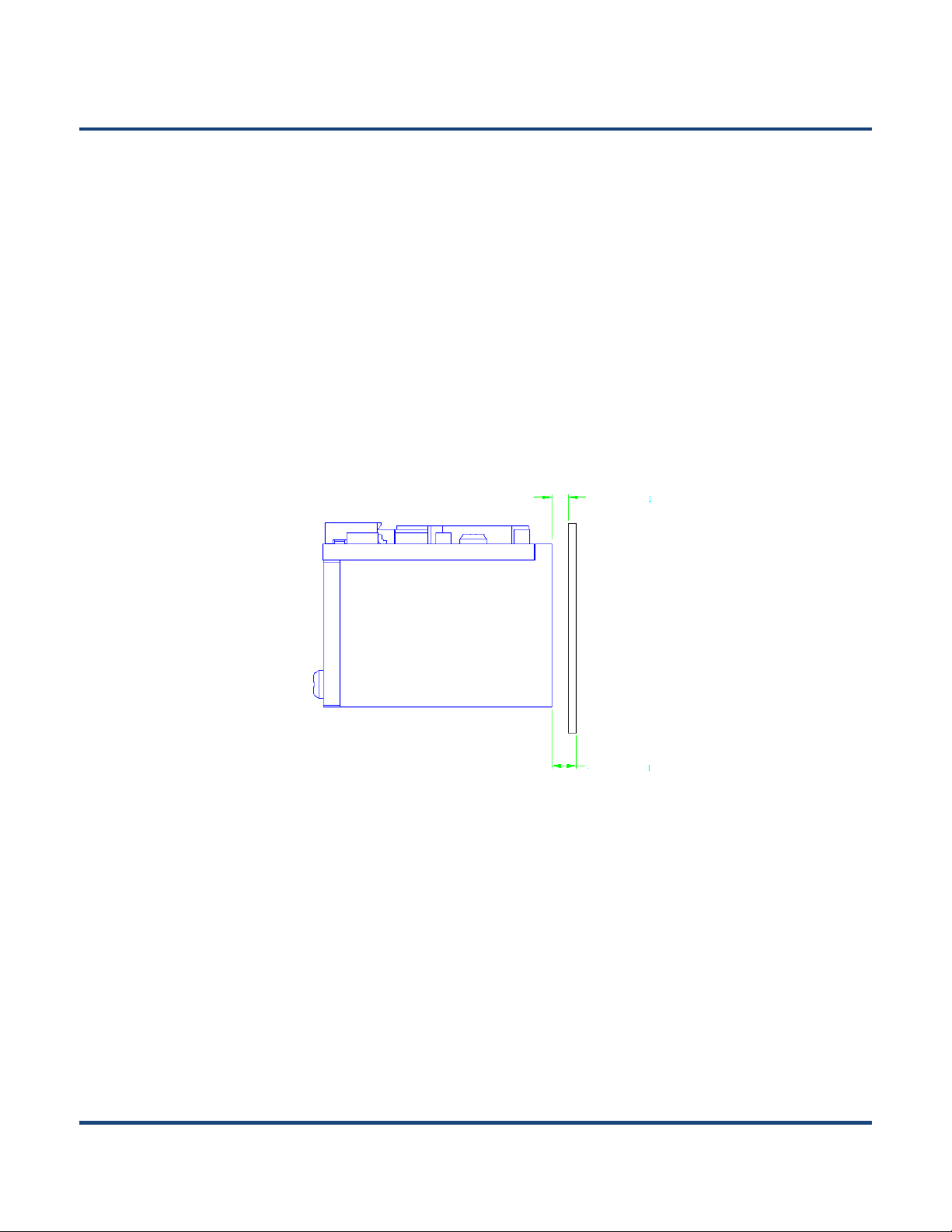
Mounting...........................................................................................................................................................7
Front View (unit: mm)...................................................................................................................................7
Side View (unit: mm)....................................................................................................................................7
Top View (unit: mm).....................................................................................................................................8
Chapter 3 Electrical Specifications..................................................................................................................9
Power Supply...................................................................................................................................................9
Ripple Noise.....................................................................................................................................................9
DC Characteristics.........................................................................................................................................10
Operating Voltage......................................................................................................................................10

Operating Current......................................................................................................................................10
Chapter 4 Interfaces.........................................................................................................................................11
Host Interface Connector...............................................................................................................................11
Dimensions of the Host Interface Connector (unit: mm)...........................................................................12
FFC Cable (unit: mm) ................................................................................................................................13
Communication Interfaces .............................................................................................................................14
Control Interfaces...........................................................................................................................................15
Reset..........................................................................................................................................................15
Trigger........................................................................................................................................................15
Beeper........................................................................................................................................................16
Good Read LED.........................................................................................................................................17
Chapter 5 Development Tools ........................................................................................................................18
EVK ................................................................................................................................................................18

1
Chapter 1 Introduction
Overview
TM
Illumination
Aimer
The LV3296 OEM scan engines, armed with the Rakinda patented , a computerized image
recognition system, bring about a new era of 2D barcode scan engines.
The LV3296’s 2D barcode decoder chip ingeniously blends technology and advanced chip design
& manufacturing, which significantly simplifies application design and delivers superior performance and
solid reliability with low power consumption.
The LV3296 supports all mainstream 1D as well as PDF417, QR Code (QR1, QR2, Micro QR), Data
Matrix and GS1-DataBarTM(RSS) (Limited/ Stacked/ Expanded versions).
The LV3296 has two red LEDs for supplementary lighting, making it possible to scan barcodes even in
complete darkness. The illumination can be programmed On or Off.
The LV3296 uses red LEDs for illumination, so the engine shows better reading performance on
barcodes printed in non-red colors. For applications involving red barcodes, it is advised to turn off the
engine’s illumination and use non-red supplementary lighting (such as green) instead. The user can
conduct some tests to determine the proper wavelengths to be used.
The LV3296 has a view finder that produces a solid circle-shaped aiming pattern to help the user to
easily position the target barcode within the engine’s field of view to increase scan efficiency. The aiming
pattern can be turned On or Off. It is advisable to turn it on when scanning barcodes.

2
Chapter 2 Installation
General Requirements
ESD
Dust and Dirt
Ambient Environment
Operating Temperature -20℃~ 50℃
Storage Temperature -40℃~ 80℃
Humidity 5% ~ 95% (non-condensing)
Thermal Considerations
ESD protection has been taken into account when designing the LV3296 and the engine is shipped in
ESD safe packaging. Always exercise care when handling the engine outside its package. Be sure
grounding wrist straps and properly grounded work areas are used.
The LV3296 must be sufficiently enclosed to prevent dust particles from gathering on the imager, lens
and circuit board. Dust and other external contaminants will eventually degrade the engine’s
performance.
The following environmental requirements should be met to ensure good performance of the LV3296:
Electronic components in the LV3296 will generate heat during the course of their operation. Operating
the LV3296 in continuous mode for an extended period may cause temperatures to rise on CIS and
decoder chip. Overheating can degrade image quality and affect scanning performance. Given that, the
following precautions should be taken into consideration when integrating the LV3296.
Reserve sufficient space for good air circulation in the design.
Avoid wrapping the LV3296 with thermal insulation materials such as rubber.

3
Installation Orientation
The LV3296 has two threaded mounting holes for machine screws on its bottom. The following figure
illustrates a front view of the LV3296 after correct installation.

4
Optics
Window Placement
The window should be positioned properly to let the illumination and aiming beams pass through as much
as possible and no reflections back into the engine (reflections can degrade the reading performance).
The window should be mounted close to the front of the engine (parallel). The maximum distance is
measured from the front of the engine housing to the farthest surface of the window. In order to reach
better reading performance, the distance from the front of the engine housing to the furthest surface of the
window should not exceed 3mm and the distance from the front of the engine housing to the nearest
surface of the window should not exceed 2mm.
If the window is required to be in a tilted position, the distance requirements above should be met and tilt
angle should ensure no reflections back into the lens.
Window Material and Color
CIS’s responsiveness (mainly to wavelengths of red light)should be taken into consideration when
choosing window material and color, in order to achieve the possible highest spectral transmission, lowest
haze level and homogeneous refractive index. It is suggested to use PMMA or optical glass with spectral
transmittance over 90% and haze less than 1%. Whether to use an anti-reflection coating or not depends
on the material and application needs.
≤2mm
≤3mm

5
Scratch Resistance and Coating
Scratch on the window can greatly reduce engine performance. It is suggested to use abrasion resistant
window material or coating.
Window Size
The window must not block the field of view and should be sized to accommodate the illumination
envelope shown below.
Horizontal:

6
Vertical:
Ambient Light
Eye Safety
The LV3296 shows better performance with ambient light and it is well able to handle the flicker in
fluorescent lights using 50-60Hz AC power. However, high-frequency pulsed light can result in
performance degradation.
The LV3296 has no lasers. It uses LEDs to produce illumination and aiming beams. The LEDs are bright,
but testing has been done to demonstrate that the engine is safe for its intended application under
normal usage conditions. However, the user should avoid looking into the beam.

7
Mounting
Front View (unit: mm)
Side View (unit: mm)
The illustrations below show the mechanical mounting dimensions for the LV3296. The structural design
should leave some space between components.

8
Top View (unit: mm)
Mounting Hole
M1.6

9
Chapter 3 Electrical Specifications
Power Supply
Unstable power supply or sharp voltage drops or unreasonably short interval between power-ons may
lead to unstable performance of the engine. Do not resupply the power immediately after cutting it off. The
minimum interval must exceed 2 seconds.
Ripple Noise
Acceptable ripple range (peak-to-peak) : ≤50mV (≤30mV recommended).
Do not power up the LV3296 until it is properly connected. Be sure the power is cut off before connecting
a cable to or disconnecting a cable from the host interface connector. Hot-plugging could damage the
engine.
Image sensor and decoder chip are directly fed by the input power of LV3296. To ensure the image
quality, a power supply with low ripple noise is needed.

10
DC Characteristics
Operating Voltage
Ta=25℃
Parameter
Description
Minimum
Typical
Maximum
Unit
VDD
Voltage Drain Drain
3.0
3.3
3.6
V
VIH
High Level Input Voltage
VCC-0.5
-
-
V
VIL
Low Level Input Voltage
-
-
0.5
V
VOH
High Level Output Voltage
VCC-0.3
-
-
V
VOL
Low Level Output Voltage
-
-
0.3
V
Operating Current
Ta=25℃,VDD=3.3V
Operating Current
Standby Current
Sleep Current
210mA
7mA
<5uA

11
Chapter 4 Interfaces
Host Interface Connector
PIN#
Signal
I/O
Function
1
NC
-
Not connected.
2
VDD
-
3.3V power supply.
3
GND
-
Power-supply ground.
4
RX
I
TTL level 232 receive data.
5
TX
O
TTL level 232 transmit data.
6
USB_D-
I/O
USB_D- differential data signal.
7
USB_D+
I/O
USB_D+ differential data signal.
8
NC
-
Not connected.
9
Buzz
O
Beeper output. For the information of beeper driver circuit, see the
Beeper section in this chapter.
10
LED
O
Good Read LED output. For the information of LED driver circuit,
see the Good Read LED section.
11
Reset
I
Reset signal input: Driving this pin low for 100us-500us resets the
engine.
12
nTrig
I
Trigger signal input: Driving this pin low for at least 10ms causes
the EM3296 to start a scan and decode session.
PIN1
The following table lists the pin functions of the 12-pin host interface connector on the LV3296.

12
Dimensions of the Host Interface Connector (unit: mm)
The LV3296 uses a 12-pin FPC ZIF socket (bottom contact, model: 10051922-1210EHLF) manufactured
by FCI. The socket can be connected to a host device with a FFC cable.

13
FFC Cable (unit: mm)
A 12-pin FFC cable can be used to connect the LV3296 to a host device. The cable design must be
consistent with the specifications shown below. Use reinforcement material for the connectors on the
cable and reduce cable impedance for reliable connection and stable performance.

14
Communication Interfaces
1. USB HID-KBW: Based on USB connection, the engine’s transmission is simulated as USB keyboard
input. It works on a Plug and Play basis and no driver is required.
2. USB COM Port Emulation: The USB interface on the host device is emulated as a serial port with the
same data transmission and configuration as a real serial port.A driver is required.
3. USB HID-POS: It is based on HID with no need for custom driver and is way more efficient in
communication than keyboard emulation and traditional RS-232 interface.
The LV3296 can communicate with the host device via its TTL-232 interface. This interface is applicable
to most system architectures. For those requiring RS-232, a TTL-232 to RS-232 conversion circuit
is needed.
The LV3296’s TTL-232 interface supports baud rates from 1200bps to 115200bps; it does not support
hardware flow control. Its default settings are 9600bps, 8 data bits, no parity check and 1 stop bit.
Besides, the LV3296 can also communicate with the host device via its USB interface.

15
Control Interfaces
Reset
Trigger
As a decode session involves image capture, barcode decoding and other steps, it is suggested that the
minimum interval between triggers should exceed 50ms.
The following trigger circuit is provided for reference.
B3F-4000S1
2 3
1 4
5
6
C3
100pF
CBW1608/60R
L1
C4
100pF
nTrig
R15
10K
VDD
Driving the Reset pin (PIN 11) on the host interface connector low for 100us-500us can reset the
LV3296. However, do not reset the engine at unreasonably short intervals. The minimum interval
between resets must exceed 2 seconds.
Driving the nTrig pin (PIN 12) on the host interface connector low for over 10ms causes the LV3296 to
start a scan and decode session. If barcode is decoded, the LV3296 waits for the voltage at the nTrig pin
to turn high (or the trigger to be released) after sending the data to the Host. If the trigger is
released during a scan attempt, the LV3296 immediately stops decoding.
Next decode session does not happen until the LV3296 receives active trigger signal (driving the nTrig
pin low) again.

16
Beeper
The following beeper driver circuit is provided for reference.
2N3904
Q8 AS903Q
LS1
1
2
R5
10R
R6 1K
R7
10K
VDD
BUZZ
BAT760
D2
The LV3296 provides a pin (Buzz, PIN 9) on the host interface connector that provides a PWM output to
an external driver circuit for generating audible feedback to the user to indicate statuses like power up or
good read. The PWM output is not strong enough to drive a beeper, thus a beeper driver circuit is
needed.
Table of contents