rako WA-NEX User manual

WA-NEX Instruction Manual
What is the WA-NEX?
The WA-NEX is generally used to partition a wired system that has
exceeded the maximum cable distance of the data run. Once
partitioned by a WA-NEX the two partitioned halves will behave
exactly as if it were a single wired network.
The RAKO wired system has a maximum data network length of
approximately 3000m. When using a RAK-STAR the cable length
is effectively doubled as the data travels out and returns on the
same cable. This means the maximum is reached with 1500m of
cable.
Symptoms of excessive cable length:
The symptom of this maximum data length being exceeded is that newly
added CAN devices will cause other network devices to disappear from
the system. If keypads or other devices that were previously appearing as
online start going offline as new ones are added and the system is large
then it is very likely that the total data length has been exceeded.
Example WA-NEX configuration
WA-NEX Manual Version 1.1.1

A system with approximately two fully populated RAK-Stars will be approaching the 3000m
limit in a typical installation. Obviously this can vary dramatically depending on the nature of
the installation and resulting routes taken by the cables.
Installing the WA-NEX
Connections
The WA-NEX has both punch-down and RJ11 ports that can be used to connect it to each
half of the newly partitioned system. As indicated on the board the wired network with the
Bridge should be connected to the “Master” side and the other to the “Remote” side.
Spurs
If possible it is good practice to only have a single cable coming from each of the Master and
Remote sides of the WA-NEX and to avoid using spurs While a network with multiple spurs
from the WA-NEX will operate correctly it should only be used when inadequate cabling is
present for daisy chain or star wiring.
WA-NEX Manual Version 1.1.1

NB
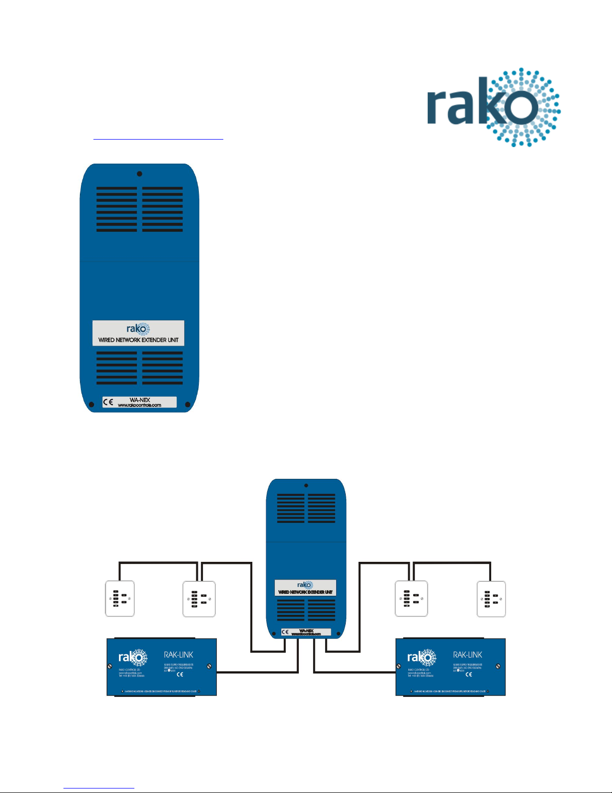
See WA-NEX Application data sheet for more information on using this product to form multiple spurs.
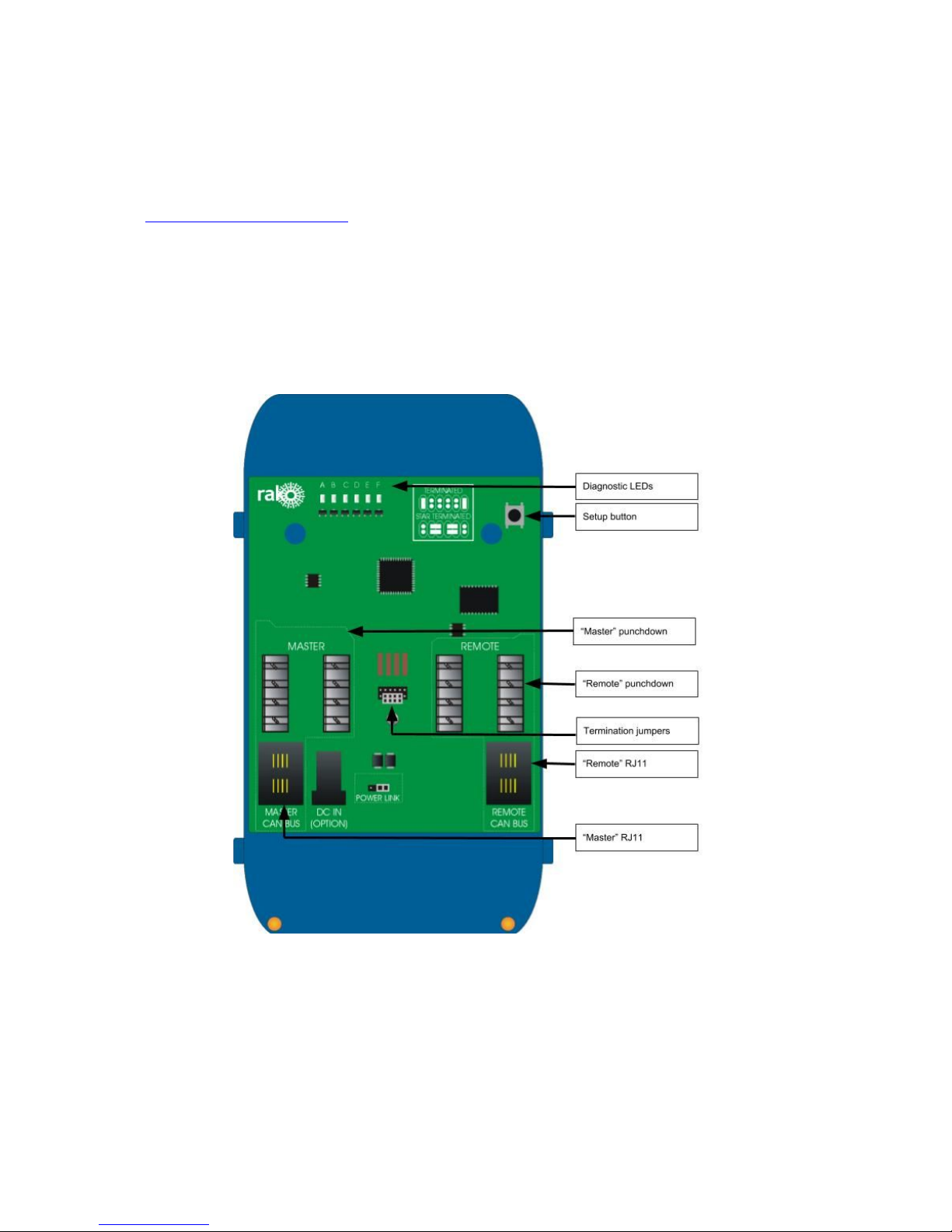
Setting jumpers and terminations
There are two sets of termination jumpers on the WA-NEX, one for each half of the newly
partitioned network. These must be terminated in the same fashion as any other Rako wired
device. As two wired networks are being connected the correct termination for each system
is required.
Terminated
For end of line termination use if the WA-NEX is
connected to anything except a RAK-Star.
Star Terminated
Use this termination if the WA-NEX is connected to
a RAK-Star.
The “Power Link” jumper can be used to connect and disconnect the 15V wired network
supply between the master and remote sides of the system. It may be that each half has its
own power source (RAKLink) and therefore it may be preferable to keep the power separate
whereas a small additional cable run created by the WA-NEX may require power from the
main network.
Adding the WA-NEX as a device
To address the WA-NEX first connect to a Bridge attached
to the Master side in the normal fashion. For full
instructions on how to connect to a Bridge see any of the
Rasoft Pro programming guides.
When the Bridge is successfully connected to Rasoft Pro it
should appear in the communications window with a green
tick next to the Bridge name.
- Select “File” - “New Device” to open the “New Device Wizard”
- Select the WA-NEX from either the “Wired” or “All” device lists.
- Give the device a suitable name, leave “Automatic ID” selected.
WA-NEX Manual Version 1.1.1

- When prompted press and hold the setup button on the WA-NEX. When the “A” status LED
begins to flash release the setup button.
Once the WA-NEX has been added as a device it will appear in device list:
NB
It is not necessary to setup the WA-NEX as a device in the software for it to successfully
partition the system: the WA-NEX can be used as a plug and play device.
It is advisable that the WA-NEX is set up for two reasons. Firstly it is a good idea to have the
presence of the device visible on the software as a record for any future work. There are
also diagnostic tools and information available from the software that may help with fault
finding if cabling problems remain on the wired network.
WA-NEX Manual Version 1.1.1

Diagnostic features of the WA-NEX
Diagnostic using circuit board LEDs
Each of the network diagnostic LEDs at the top of the PCB (A-F) gives information on the
state of either side (Master and remote) of the wired network.
A (Master In):
Blue LED. This LED will flash whenever a command is received by the WA-NEX from the
master side of the network.
B (Master Error):
Red LED. Will display solid if no network can be found on the Master side of the WA-NEX.
Will flash red if there is a network connected on the Master side but there is an error in
communication (likely cabling fault).
C (Remote In):
Blue LED. This LED will flash whenever a command is received by the WA-NEX from the
remote side of the network.
D (Remote Error):
Red LED. Will display solid if no network can be found on the Remote side of the WA-NEX.
Will flash red if there is a network connected on the Remote side by there is an error in
communication (likely cabling fault).
E (Master Out):
Blue LED. This LED will flash whenever a command is transmitted but the WA-NEX to the
Master side of the network.
F (Remote Out):
Blue LED. Blue LED. This LED will flash whenever a command is transmitted by the
WA-NEX to the Remote side of the network.
WA-NEX Manual Version 1.1.1

Diagnostic features using Rasoft Pro
Once addressed the WA-NEX can give diagnostic feedback about the state of the Rako
wired network:
Pressing “Poll” will run a diagnostic check on both sides of the system. If there is a problem
such as “Remote CAN Voltage too low” or “Short on Master Data side” it will appear to the
right of the screen in Rasoft Pro. In most cases an advised course of action will also be
given.
WA-NEX Manual Version 1.1.1
Table of contents