Raleigh Audio Standard Extreme RAKK dac Mark III User manual

RAKK dac
raleigh
audio
Mark III
Standard
Extreme RAKK dac
Assembly Manual
Version 1.1 © 2014 Raleigh Audio

This completed Extreme RAKK dac has a silver face plate and knobs. A black faceplate and knobs is available.
1

GeneralInformation
The Extreme RAKK dac is a semi-custom kit, which means that several standard offerings can
be combined in different ways. You can choose to have an optional volume control and optional
select switch. You can choose to have one to six inputs which may be a mix of SPDIF,
AES/EBU, I2S and USB. These are covered in this manual although all of the possible
combinations are not shown. However, those things not shown can be easily inferred from other
things that are shown.
This kit is relatively straightforward to build, but assumes some prior skill with a soldering iron
and some knowledge of electronic components and assembly.
Kit version
Use this manual with the Standard Extreme RAKK dac Mark III
•Use the applicable on-line manuals for component sub-assemblies.
Required Tools and Supplies
150 to 250 Watt soldering gun
35 to 50 Watt soldering iron
Phillips (cross point) screwdriver
Volt-Ohm-Milliamp Meter
Potentiometer adjustment tool (supplied)
1/16” hex (Allen) wrench (supplied)
5/64” hex (Allen) wrench (supplied)
1.5mm. hex (Allen) wrench (supplied)
2.5mm. hex (Allen) wrench (supplied)
1/4”, 5/16”, 1/2”, 9/16” open-end wrenches
Diagonal cutting pliers
Long-nose pliers
Wire stripper
Solder
Use the soldering gun only to solder the heatsink pins.
Use the soldering iron for all other components.
Support
You may contact us with questions on constructing this kit by sending an e-mail message to
2

Warnings and Cautions
Warning — a high voltage power supply (200VDC) is required to make the kit operate properly.
These voltages can be lethal. If you are not familiar with safe techniques for completing the
installation of this kit with a high voltage power supply, then you should seek someone who is
qualified to help you construct this kit safely. If you wish to review safe practice, consult the
ARRL Handbook for Radio Amateurs (www.arrl.org or often at used book stores), which has a
section on high voltage safety. Although they are usually referring to 1000v+, the techniques are
still applicable. As the purchaser, you assume responsibility for safe assembly, testing, and
application of this kit.
Caution – Use only solder that is intended for electrical circuits. Do not use acid or corrosive
flux of any kind.
Caution – Any MOSFET is subject to damage by static electricity. Thus, the MOSFETs need
special care and handling especially when the relative humidity is low. Make sure to discharge
any static electrical charge from your body before handling a MOSFET. You can discharge your
body by touching a water faucet or grounded electrical appliance.
Soldering Notes
To a large extent, the success of your kit-building endeavor depends on your ability to solder
properly. Aside from experience, there are two pretty important factors in this success. The first
is the soldering equipment. I recommend using a temperature controlled soldering station,
although any good soldering iron of 40 watts or greater will do. There are many soldering
stations on the market; I have had good experience with the moderately priced Hakko Model
936. If you do have or purchase a soldering station, or even use your existing soldering iron, I
have found a chisel style tip of about 2mm-2.5mm width to be the most useful. You can use the
flat part for large solder joints and the corner for small solder joints. The second factor is the
selection of the solder you will use. The PC boards and most of the electrical components in the
kit are lead-free, as the movement in the EU has forced manufacturers to remove the lead (and
other dangerous heavy metals) from their products. Decent (notice, I didn’t write “good”) lead-
free solder exists, such as Cardas Tri-Eutectic, but it is not so easy to use unless you have some
soldering experience. Lead-free solder tends to melt in a sluggish way and the resulting solder
joints are not the customary shiny silver color, so it’s difficult to avoid “cold” solder joints
without experience. It’s up to you to decide what to use. Choose based on your experience. I
use Cardas Quad Eutectic and can recommend it without reservation; however other high quality
solders may work just as well. Take care in handling electronic solder as most of it still contains
a significant quantity of lead. Wash your hands thoroughly after construction sessions and keep
all kit materials well out of the reach of small children.
Even though there is a “component side” and solder side” to the board, your might find it more
convenient to solder the leaded components from the component side.
3

TableofContents
General Information ......................................................................................................................................................2
Table of Contents...........................................................................................................................................................4
Component Parts ...........................................................................................................................................................5
Assembly Instructions ...................................................................................................................................................6
Assemble the Printed Circuit Boards.........................................................................................................................6
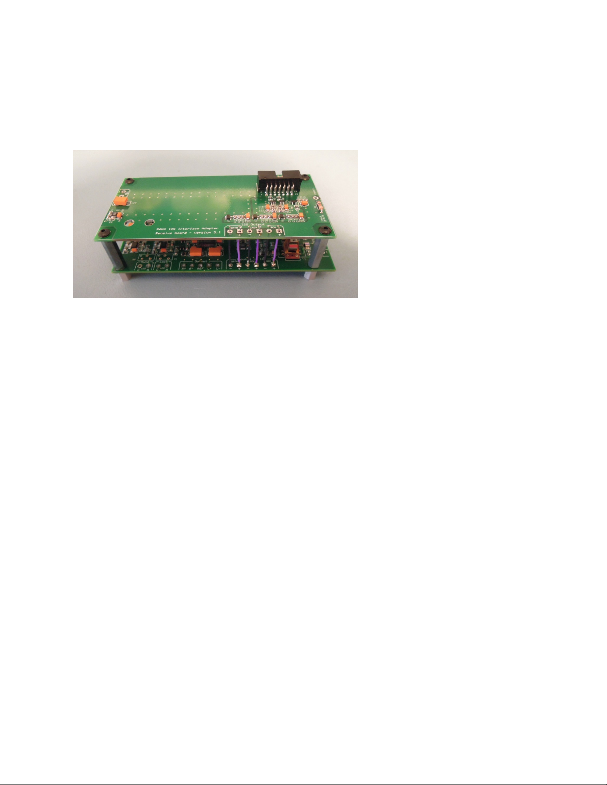
Pre-assemble Standard (single input) I2S Adapter with the RAKK dac....................................................................7
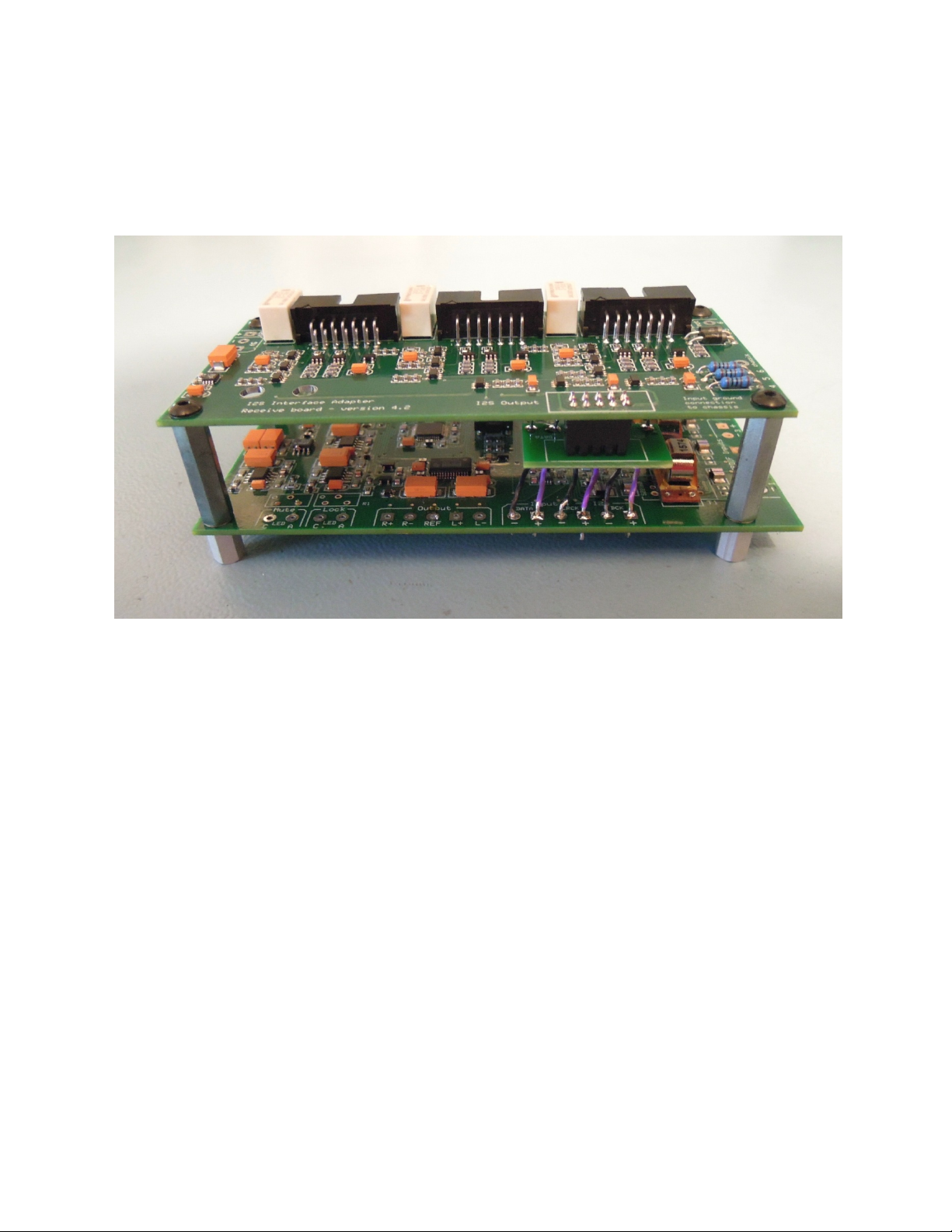
Pre-assemble (three-input) I2S Adapter with the RAKK dac....................................................................................9
Pre-wire the printed circuit boards ..............................................................................................................................12
Pre-wire the 10V Regulator (for the RAKK dac) ....................................................................................................13
Pre-wire the 5V Regulator (for the I2S Adapter).....................................................................................................13
Pre-wire the 8V Regulator (for the USB Adapter) ..................................................................................................14
Pre-wire the 12V Power Supply (for the Active Output).........................................................................................15
Pre-wire the Active Output......................................................................................................................................17
Pre-wire the RAKK dac and I2S Interface Adapter (if used) ..................................................................................19
Pre-wire the Power Transformer .................................................................................................................................21
Panel Preparation.........................................................................................................................................................23
Bottom Panel Preparation ........................................................................................................................................23
Back Panel Preparation............................................................................................................................................24
Side Panel Preparation.............................................................................................................................................25
Front Panel Preparation ...........................................................................................................................................25
Panel Assembly ...........................................................................................................................................................26
Bottom Panel Assembly ..........................................................................................................................................26
Back Panel Assembly ..............................................................................................................................................35
Front Panel Assembly..............................................................................................................................................41
Final Assembly and Wiring.........................................................................................................................................43
Wire the Bottom Panel to the Back Panel................................................................................................................43
Wire the Bottom Panel to the Front Panel ...............................................................................................................48
Assemble the Panels ................................................................................................................................................52
Final Adjustments........................................................................................................................................................57
Adjust the Constant Current Sources.......................................................................................................................57
Final Assembly............................................................................................................................................................58
Parts List......................................................................................................................................................................59
Circuit kits ...............................................................................................................................................................59
Front Panel Options .................................................................................................................................................59
Input Options ...........................................................................................................................................................60
Extreme Kit Contents ..............................................................................................................................................61
Document version history............................................................................................................................................64
4

ComponentParts
Depending upon the feature mix that you have chosen, the boards that you will assemble will
vary. In all cases your project will include a RAKK dac, an Active Differential Output board, a
Low-Voltage Power System Standard Regulator and a Low-Voltage Power System Standard
Power Supply. You may also have chosen to have an I2S adapter or USB adapter and their
associated Regulators.
The Low-Voltage Power System components can be configured to supply any voltage that is
required. The voltages used are as follows:
RAKK dac: 10V Standard Regulator
I2S Adapter: 5V Standard Regulator
USB Adapter: 8V Standard Regulator
Active Output: 12V Standard Power Supply
5

AssemblyInstructions
Before you start, read through the instructions completely to the end. Inventory the kit contents
to become familiar with the parts and to make sure you have everything.
The assembly sequence is as follows:
1. Assemble all of the printed circuit boards
2. Pre-wire the printed circuit boards
3. Pre-wire the power transformer
4. Install PC boards and the power transformer on the bottom panel
5. Assemble the components on the back panel
6. Assemble the components on the front panel
7. Assemble the panels
8. Wire everything together
AssemblethePrintedCircuitBoards
The RAKK dac, I2S adapter and the USB adapter are pre-assembled because their surface
mounted components require special assembly tools and techniques. However, you may install
pulse transformers on the RAKK dac. You will assemble the Active Output and the power
supplies.
While assembly of all of the boards is straight-forward, the Active Output is the most complex.
Therefore, I recommend that you leave that board until you have assembled all of the other
boards.
The assembly manuals for the boards include installation instructions that you will not use.
Rather than using those general instructions, you will follow the specific installation
instructions contained in this manual.
There are two sizes of stranded wire provided with the kit, #22 and #20. The larger diameter #20
is used for power and high voltage. The smaller diameter #22 is used for signal and low voltage.
Where a wire is to be connected to a PC board, prepare the end by stripping ⅛” insulation and tin
the bare wire. For other connections, strip ¼” and tin the end. Where a twisted-pair is called for,
provide about four or five twists per inch. Twisting wires together will shrink their length
slightly so you need to take this into account. With a very few exceptions, which are explicit,
insert the wire into the pad from the bottom, or solder side, of the board. Wires should be
dressed neatly as close to the bottom of the enclosure as possible.
Several of the individual kits have a small amount of wire included with them. Use that wire for
the kit it came with rather than using the bulk amount that is provided with the Extreme kit.
Otherwise you will end up short of wire.
Referring to the applicable on-line manuals, assemble the boards now.
6

PreassembleStandard(singleinput)I2SAdapterwiththeRAKKdac
————————————————————————————
Skip this section if you do not have a Standard (single input) I2S Adapter.
————————————————————————————
Wire the I2S Output on the I2S Adapter
1. Mount four 1” standoffs on the bottom of the I2S Adapter and secure with 6-32 screws.
2. Insert a ⅜” 6-32 setscrew about half-way into each 1” standoff.
3. Install a ⅜” standoff as a nut on each of the four 1” standoffs.
4. Cut three pieces of #22 black wire, each 1⅜” long.
1⅜” is the length of the two standoffs, which may be used as a gauge.
5. Cut three pieces of #22 violet wire, each 1⅜” long.
6. Strip ¼” of insulation from each end of the wires and tin the ends by melting a little solder
onto the stripped ends.
7. Insert the three black wires from the bottom of the board into the following three locations:
•DATA -
•LRCK -
•BCK -
8. Solder and trim the leads.
7

9. Insert the three violet wires from the bottom of the board into the following three locations:
•DATA +
•LRCK +
•BCK +
10. Solder and trim the leads.
————————————————————————————
Mount the I2S Adapter to the RAKK dac
Steps preceded by a “note” (♪) deal with components which must be oriented properly.
11. Remove the ⅜” standoffs from the 1” standoffs on the adapter.
♪
12. Set the I2S Adapter on top of the RAKK dac such that the I2S Output pads on the I2S
Adapter align with the “Input 4 – I2S” pads on the RAKK dac.
13. Insert the six I2S interface wires into the proper pads on the RAKK dac.
14. Install the four ⅜” standoffs as nuts to hold the two pieces together.
15. Solder the six interface wires.
————————————————————————————
8

Preassemble(threeinput)I2SAdapterwiththeRAKKdac
————————————————————————————
Skip this section if you do not have a (three-input) I2S Adapter.
————————————————————————————
Wire the I2S Output on the small adapter board
The three-input I2S adapter has a connector on its I2S output. This connector will plug into a
small adapter board, which in turn will be soldered onto the RAKK dac.
1. Connect a 1” (male/female) standoff together with a ⅜” standoff.
This may be used as a gauge for cutting the following wires.
2. Cut three pieces of #22 black wire, each 1⅜” long.
3. Cut three pieces of #22 violet wire, each 1⅜” long.
4. Strip ¼” of insulation from each end of the wires and tin the ends by melting a little solder
onto the stripped ends.
9

5. Insert the three black wires from the bottom of the small adapter board into the following
three locations:
•DATA -
•LRCK -
•BCK -
6. Solder and trim the leads.
7. Insert the three violet wires from the bottom of the small adapter board into the following
three locations:
•DATA +
•LRCK +
•BCK +
8. Solder and trim the leads.
♪
9. Set the small adapter board on top of the RAKK dac such that the I2S Output pads on the
small adapter board align with the “Input 4 – I2S” pads on the RAKK dac.
10. Insert the six I2S interface wires into the proper pads on the RAKK dac.
11. Solder and trim the leads.
————————————————————————————
10

Mount the I2S Adapter to the RAKK dac
Steps preceded by a “note” (♪) deal with components which must be oriented properly.
12. Mount four 1” standoffs on the bottom of the I2S Adapter and secure with 6-32 screws.
♪
13. Set the I2S Adapter on top of the RAKK dac such that the I2S Output connector on the I2S
Adapter aligns with the pins on the small adapter board.
14. Plug the I2S Adapter into the small adapter board.
15. Install the four ⅜” standoffs as nuts to hold the two pieces together.
16. Form the wires neatly and make sure that the small adapter board is parallel to the I2S
Adapter and the connector is inserted properly. .
————————————————————————————
11

Prewiretheprintedcircuitboards
In the following steps, the wires should be inserted into the solder side of the board. “Preparing a
wire” means to strip ⅛” of insulation from both ends of the wire and tin the ends.
Because each wire has a “from” end and “to” end, and only one end is pre-wired, some pads are
not wired in this section. A signal line or a function will likely have the same name on the
“from” end as it does on the “to” end, therefore don’t just go by the name when you install the
wire. Rather, check that you are installing it on the proper board.
Basically there are two ways to make a twisted pair or a multi-wire cable. The quick and easy
way is to use an electric drill. So if you have a variable speed drill, all you have to do is to put
the wires together in the drill chuck and turn on the drill. It might take a little practice to get the
tension and speed right but once you get the knack, it is quick and easy to do. If you don’t have a
drill handy, the old-fashioned way of manually twisting the wires works fine. I have described
how I do it here. To make a multi-wire cable, first make a twisted pair and then wrap a third
wire around the twisted pair following the lay of one of the wires. Then stretch this new wire like
you did the others. Follow with a fourth and fifth wire as needed.
About 5% shrinkage occurs when making a twisted pair. So for example, if you wanted a 10”
long twisted pair, you would make it from two 10½” wires. It would be better to err a little on the
long side because you can always trim the length when you install the twisted pair.
————————————————————————————
12

Prewirethe10VRegulator(fortheRAKKdac)
Note that even though the power input on the RAKK dac Mark III is labeled “12V,” it has
been determined that 10V power provides better sonic quality.
————————————————————————————
1. Prepare a 20” #22 red/black twisted pair.
•Connect the red wire to the DC Output “+” pad.
•Connect the black wire to the DC Output “-” pad.
————————————————————————————
Skip the following step if you do not have a 3-input I2S Adapter.
2. Prepare a single 22” #22 red wire.
•Connect the wire to the DC Output “+” pad.
•Wrap the wire around the red/black twisted pair.
————————————————————————————
Skip the following step if you do not have a TOSLIKK adapter.
3. If you have a TOSLINK input, prepare a 19” #22 red/black twisted pair.
•Connect the red wire to the DC Output “+” pad.
•Connect the black wire to the DC Output “-” pad.
————————————————————————————
Prewirethe5VRegulator(fortheI2SAdapter)
Skip this section if you do not have an I2S Adapter.
————————————————————————————
4. Prepare a 22” #22 red/black twisted pair.
•Connect the red wire to the DC Output “+” pad.
•Connect the black wire to the DC Output “-” pad.
————————————————————————————
13

Prewirethe8VRegulator(fortheUSBAdapter)
Skip this section if you do not have a USB Adapter.
————————————————————————————
5. Prepare a 16” #22 red/black twisted pair.
•Connect the red wire to the DC Output “+” pad.
•Connect the black wire to the DC Output “-” pad.
————————————————————————————
Skip the following two steps if you do have a three-input I2S Adapter
6. Install a 1K resistor in location R5.
7. Connect a 7” #20 green wire to the “chassis” pad.
————————————————————————————
14

Prewirethe12VPowerSupply(fortheActiveOutput)
————————————————————————————
8. Install a 10K resistor in location R4.
————————————————————————————
9. Prepare an 11” #22 red/black twisted pair.
•Connect the red wire to the DC Output “+” pad.
•Connect the black wire to the DC Output “-” pad.
————————————————————————————
10. Prepare a 7” long #20 green wire and connect it to the DC Output “+” pad.
————————————————————————————
11. Prepare a 13” #22 white/violet twisted pair.
•Connect the white wire to the LED “C” pad.
•Connect the violet wire to the LED “A” pad.
————————————————————————————
12. Prepare a 6” #20 white/black twisted pair.
•Connect the twisted pair to the inner-most “AC Input” pads.
————————————————————————————
13. Fabricate a T-shaped AC power cable as follows:
•Cut a #20 black wire, 7½ inches long. Do not strip the ends.
•Cut a #20 black wire, 21 inches long. Do not strip the ends.
•Cut a #20 white wire, 22½ inches long. Do not strip the ends.
•Align the white wire with the longer black wire and twist them together for about 16”.
•Align the other black wire with the other end of the white wire and twist them together
for 4”.
•Go back to the first pair (that you twisted to 16”) and continue the twist until you get to
the junction of the second pair.
•Now twist the two black wires together until you get to the end. Don’t worry if the two
black wires are different length – you will trim them later.
————————————————————————————
15

14. Wire the AC cable that you just fabricated:
•Strip and tin the end of the 4½” part of the black/white twisted pair.
•Observing the same black/white orientation as the 5” black/white twisted pair that you
just connected, connect this twisted pair to the outer-most “AC Input” pads.
————————————————————————————
16

PrewiretheActiveOutput
————————————————————————————
Wire the “From RAKK dac” inputs on the Active Output
1. Prepare a 4” #22 black wire.
•Connect it to the “REF” pad.
2. Prepare a 4” #22 orange/black twisted pair.
•Connect the orange wire to the “R+” pad.
•Connect the black wire to the “R-” pad.
3. Prepare a 4” #22 blue/black twisted pair.
•Connect the blue wire to the “L+” pad.
•Connect the black wire to the “L-” pad.
————————————————————————————
Wire the External Mute
4. Using a craft knife cut a gap in the trace that connects the two “external mute”
pads.
5. Prepare a 24” #22 black/black twisted pair.
•Connect the two wires to the two “external mute” pads.
————————————————————————————
Wire the Volume Control on the Active Output
(skip this section if you do not have a volume control)
6. Prepare a 5½” #22 blue/black twisted pair.
•Connect the blue wire to the volume control “L+” pad.
•Connect the black wire to the volume control “L-” pad.
7. Prepare a 4½” #22 orange/black twisted pair.
•Connect the orange wire to the volume control “R+” pad.
•Connect the black wire to the volume control “R-” pad.
————————————————————————————
17

Wire the Ground on the Active Output
8. Connect a 13” #20 green wire to the “chassis” pad.
————————————————————————————
The Line Input pads are not used.
18

PrewiretheRAKKdacandI2SInterfaceAdapter(ifused)
————————————————————————————
Wire the Input Select on the RAKK dac and I2S Interface Adapter
The RAKK dac offers four inputs: three SPDIF or AES/EBU inputs and one I2S input. Inputs 1
through 3 are the SPDIF or AES/EBU inputs and Input 4 is always the I2S input, even if you are
using only a single input.
There are two versions of the I2S Adapter. One offers a single input and the other provides three
inputs. If you have the version that has a single input, there is no need to pre-wire it. If you have
the version that has three inputs, you will need to pre-wire the input selection.
Selection for Input 4 is pre-wired as part of the pre-wire for the RAKK dac. Selection for Inputs
5 and 6 are part of the pre-wire of the I2S Adapter.
While there is a possibility of having six inputs, usually there will be fewer. Note that there is an
arbitrary association between each input and the position of the Input Select switch that selects
that input. For example, the third position on the Input Select switch may be wired to select
RAKK dac input 4, or I2S input 6.
19
Table of contents
Other Raleigh Audio Media Converter manuals