Ramble FX KISMET User manual

™
USER GUIDE
Analog Tone. Digital Fun.
Ramble FX presents

Introduction ....................................................................................................................... 1
Connections...................................................................................................................... 2
Layout........................................................................................................................................ 3
Memory................................................................................................................................... 5
Saving Presets.................................................................................................. 6
Using Presets..................................................................................................... 7
Expression............................................................................................................................ 9
Connecting an Expression Controller ................................ 10
Setting Expression Control................................................................14
Using Expression Control...................................................................16
Calibrating an Expression Pedal ................................................17
MIDI Control..................................................................................................................... 19
Connecting a MIDI Controller.....................................................19
Setting Kismet’s MIDI Channel.................................................. 20
Controlling Kismet with MIDI....................................................... 21
Saving with MIDI......................................................................................... 22
Operation............................................................................................................................ 24
Specifications................................................................................................................... 25
Policies ..................................................................................................................................... 26
CONTENTS
CONTENTS
Congradulations! You are in possession of an exciting distortion pedal that gives you the ultimate in
creative control over your tone.
Thank you for supporting Ramble FX. Ramble FX is a small company that makes original effect pedals
with innovative features and player-friendly control.

Guitar players will always be drawn to the tone and feel of analog effects. All of the
"flaws" that come with sending a guitar signal through an analog circuit add up to a
rich and familiar tone. Digital effects convert the signal to digital data and process it
with exacting algorithms. This works for some effects, but distortion is different. Guitar
distortion is not hi-fi, but a mix of non-linear amplification, clipping, and intermodula-
tion that makes for a complex, harmonically rich tone.
Kismet’s Solution We first designed a great distortion pedal and then added a digital
microcontroller that is able to change the internal resistances in Kismet’s analog circuit
based on knob positions, presets, expression control, or MIDI commands.
Analog Distortion Kismet’s audio path is 100% analog. At lower gain, one set of
diodes produces a touch sensitive overdrive. As gain increases, a second set of diodes
begins clipping for higher gain with just the right amount of compression. Progressively
sculpting the distortion this way gives Kismet a wide and musical gain range.
Preset Memory Kismet can save all knob settings to each of its four memory positions.
A footswitch or toggle switch can cycle through all of the presets or toggle back and
forth between any two.
Expression Control Control any or all settings, in any amounts, any directions, all at
the same time. Save one set of knob positions for the “heel,” another for the “toe,” and
Kismet will mix and morph all settings at the same time with the expression pedal.
MIDI Control Expand Kismet’s memory to that can be any combination
of preset or expression settings. Take continuous control of any settings, and more.
INTRODUCTION
INTRODUCTION
CONNECTIONS
CONNECTIONS
INPUT
1/4” TS (TIP, SLEEVE) mono cable. Input impedance is approximately 1 M .
OUTPUT
1/4” TS mono instrument cable. Output impedance is approximately 1k .
EXPRESSION
1/4” TRS (TIP, RING, SLEEVE) stereo jack. Most expression or volume pedals can be
used. Refer to Fig. 7 for proper wiring and Fig. 11 for calibration.
MIDI
Non-standard 3.5mm TRS connector (Page 19).
REQUIRED: 2.1mm, center negative polarity. This is
the most common effect pedal power connection.
5.5mm outer diameter
2.1mm inner diameter
Fig. 1 DC power connection.
1 2
9VDC
60 mA
(minimum)
(maximum)
DC POWER INPUT
i
INPUT is for Instrument-level voltages only. Kismet is
not intended for use in an amplifier’s effects loop.

GAIN BASS MIDS
ON
1 2 3 4
VOLUME TREBLE
B
Y
P
A
S
S
Fig. 2 Kismet layout
This toggle switch determines if the
footswitch below it will cycle
through each preset or toggle back
and forth between two (Fig. 5)
3
Output
Expression control input can be a
volume pedal (Fig. 8) or a passive
expression pedal (Fig. 7)
9V DC max 60 mA
min
Momentary toggle. Tap left or right to
change memory positions. Hold to the
left to begin a preset memory save, hold
to the right to begin an expression save
This LED is ON when the
internal settings match the
physical knob positions
Set this to match the taper of the
expression pedal or to the position that
creates the best sweep from ‘heel’ to
‘toe’ (page15)
MIDI input (Page 19)
4
Relay based true
bypass switching
Solid ------------- Current memory position
Moving ---------- Expression control active
Fading on/off --- MIDI control active
Blinking ---------- Save in progress
Instrument input

Fig. 4 How to save settings to memory.
Done! Blinking stops
1 2 3 4
FINISH
MEMORY
SAVE
3HOLD
LEFT
1 2 3 4
Blinking starts
BEGIN
MEMORY
SAVE
1HOLD
LEFT
SAVING PRESETS
Save settings to memory by holding the center toggle to the left twice: once to begin a save, and
once to end. Knobs can be adjusted before or during a save. Tap the left footswitch to exit a save.
Kismet has four memory positions to save presets. Each memory position saves all five
knob positions. Recall a memory position (Fig. 5) by tapping the left footswitch or the
center toggle switch. The internal resistances will be changed according to the saved
presets. LIVE SETTINGS indicates that all five knobs match the internal settings.
MEMORY INDICATION
The status of Kismet’s internal settings can
always be determined by the four bottom
LEDs and the LIVE SETTINGS LED. For
preset memories, the LEDs appear as seen
in Figure 3. The LIVE SETTINGS LED is lit
when all five knob positions match the
internal settings. When Kismet is bypassed,
the status LEDs will dim, but remain on.
Be aware that when Kismet is set to a
memory, its settings are changed internally
and may not match the physical knob
positions.
ALSO: the same LED indications are used
while saving (Fig. 4) except they will be
blinking.
1 2 3 4
LIVE SETTINGS
1 2 3 4
1 2 3 4
1 2 3 4
1 2 3 4
Fig. 3 LED indication of memory
ONE
TWO
THREE
FOUR
5 6
MEMORY
MEMORY
TAP
LEFT
TAP
RIGHT
Memory 3 selected
(for example)
1 2 3 4
SELECT
MEMORY
POSITION
2
NOTE: Exit without saving at any time by pressing the left footswitch.
i
i

SAVING PRESETS (continued)
Saving presets to memory can be done at any time, even when Kismet is currently set to a memory
or is in expression mode. Because of that, the knob positions may not match the actual, internal
settings. It is the actual settings that are saved, i.e., what you hear is what you save. Settings are
saved to EEPROM type memory and are not lost when power is disconnected.
USING PRESETS
When Kismet recalls a preset memory position, its internal settings change and the physical knob
positions will likely not match. While set to a preset, it is still possible to change any setting by
turning its knob. That setting will be “released” from memory and changed to match the knob
position. If all five knobs are changed, Kismet will be in LIVE SETTINGS mode.
THREE WAYS TO CHANGE PRESETS
1. The center toggle switch will advance to the next memory position every time it is tapped to
the right, or to the previous memory position every time it is tapped to the left.
The left toggle switch, TOGGLE/CYCLE, sets the function of the left footswitch, TOGGLE/CYCLE.
2. Set to CYCLE, the footswitch will advance to the next memory position every time.
3. Set to TOGGLE, the footswitch will change back and forth between two memory positions.
LIVE SETTINGS can be thought of as a fifth memory position that matches the current knob
positions. It is reached by selecting the next memory after memory four, or the previous memory
before memory one. It can also be reached by holding the TOGGLE/CYCLE footswitch.
THREE WAYS TO CHANGE PRESETS (continued)
1 2 3 4
LIVE SETTINGS
1 2 3 4
1 2 3 4
Fig. 5 Three ways to change presets.
7 8
NOTE: Tapping the
center toggle is an easy
way to select which two
memories are toggled.
NEXT
or
PREVIOUS
1
NEXT
2
BACK
&
FORTH
3
TAP
LEFT
TAP
RIGHT

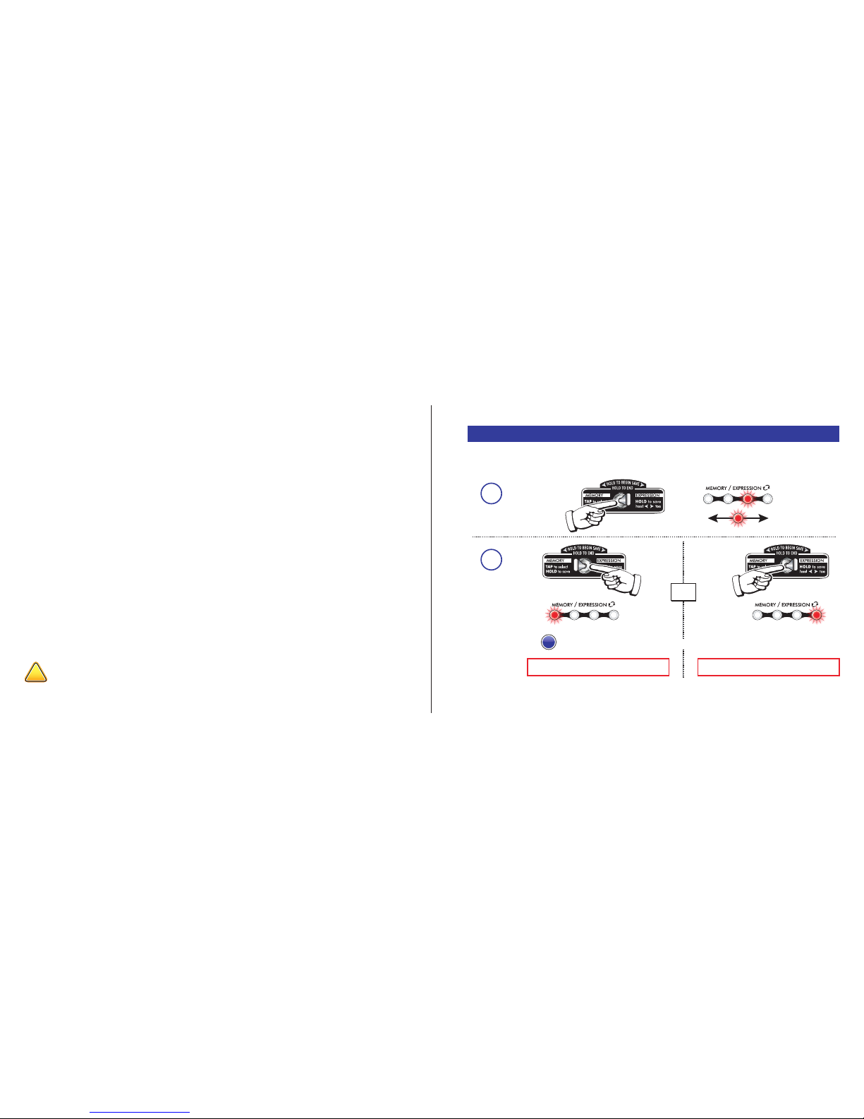
Kismet’s expression input enables complete and continuous control over any settings,
in any amounts, and in any directions, all at once. It works by saving any combination
of all five settings (volume, gain, bass, mids, treble) twice, once for the “heel” (expres-
sion pedal rocked back) and once for the “toe” (rocked forward). When the expression
pedal is active, all five settings are swept at the same time, morphing between “heel”
and “toe” settings.
ANATOMY OF THE EXPRESSION CONNECTION
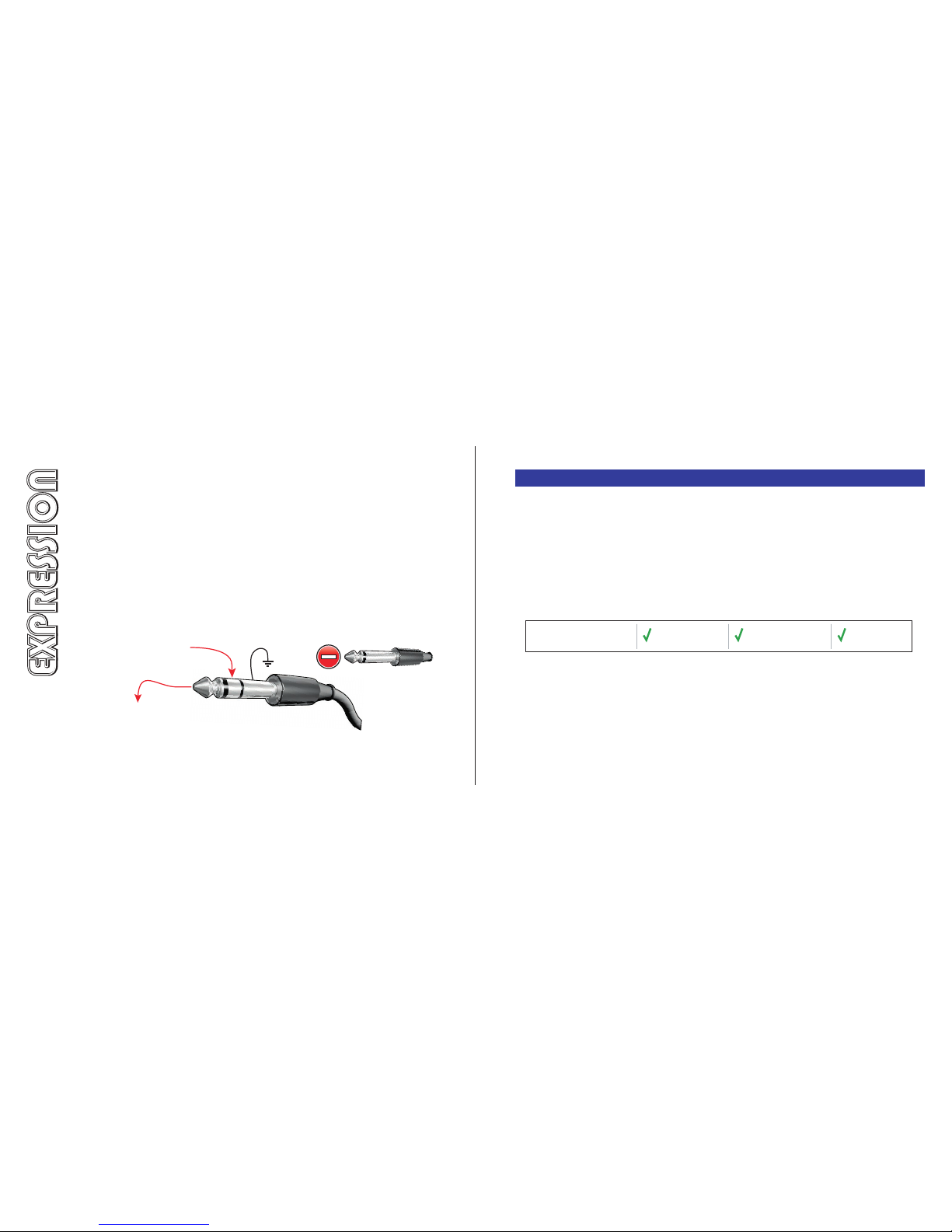
Kismet’s expression input is a ¼” TRS, or stereo jack. TRS stands for TIP, RING, SLEEVE,
and describes the three connections of the plug. Kismet sends a constant 5 volts out
through the RING connection and measures the voltage that returns on the TIP
connection.
Fig. 6 Expression cable plug for Kismet’s expression input.
Ground
T
i
p
R
i
n
g
l
e
e
v
e
S
5V constant out of Kismet
and into expression device
Voltage returned from
expression device into
Kismet to be measured
CONNECTING AN EXPRESSION CONTROLLER
There are three types of expression controllers that can be used:
1. Expression pedal (below)
2. Volume pedal (Page 12)
3. Control voltage (CV) source (Page 13 - do not attempt without reading first)
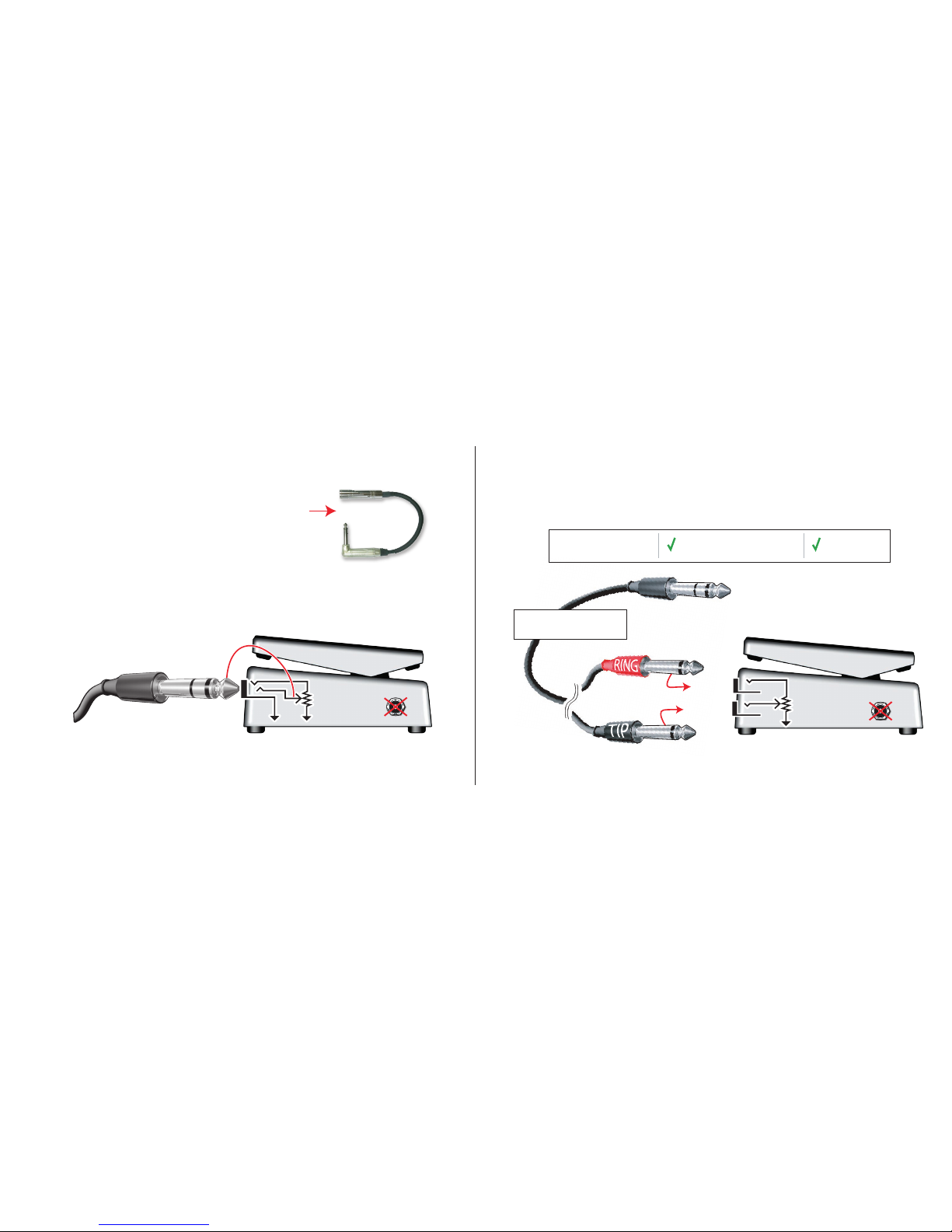
1. EXPRESSION PEDAL
An expression pedal is a foot-controlled potentiometer with only one stereo jack. A single cable
contains both the input and the output wires. A fixed voltage enters on one wire, and a fraction of
that voltage is sent back on a separate wire. The taper, or sweep (Page 15) of most expression
pedals is linear. Most expression pedals can be used with Kismet.
REQUIRED CABLE: One TRS, stereo instrument cable. Expression pedals that use a TS, mono
cable, such as Line 6, are NOT compatible with Kismet.
POWER: Expression pedals must NOT be powered. The only exception is an expression pedal that
uses power only to vary resistances via opto-couplers and has an entirely passive signal path.
EXTRA SETTINGS: Some expression pedals have knobs that can limit the minimum or maximum
settings. It is best to set the output so that it reaches the full 0-100% range. Anything less will
require calibration (Page 17).
Connects with a Has the correct
stereo cable connector polarity Not powered
Compatibility Check:
910
Do not insert a TS mono plug
into the expression input.
EXPRESSION
EXPRESSION

Wrong polarity?
A polarity changing
adapter is available
from Ramble FX.
1. EXPRESSION PEDAL (continued)
If a connected expression pedal cannot turn ON expression control (Fig. 10), try calibrating it as
described on page 17. If that fails, or expression control still will not turn ON, the polarity is most
likely wrong and the expression pedal should be DISCONNECTED. It is safe to try because Kismet has
over-current protection, but do not leave it connected.
REQUIRED CONNECTION POLARITY:
Tip-to-wiper (see Fig. 7). Not all pedals use
this polarity. Expression pedals with the wrong
polarity can be made compatible with a
polarity-reversing adapter, available at
www.ramblefx.com/polarity-adapter.
Required polarity: tip-to-wiper
POTENTIOMETER
Fig. 7 Expression pedal connection showing tip-to-wiper polarity.
From Kismet
expression
jack
DC INPUT
2. VOLUME PEDAL
A volume pedal is a foot-controlled potentiometer with separate input and output connections. A
voltage enters one jack and a fraction of that voltage is sent out the other jack. It usually has a
logarithmic (audio) curve, or sweep (Page 15). Most volume pedals are compatible with Kismet.
INPUT JACK
POTENTIOMETER
TO KISMET EXPRESSION JACK
OUTPUT JACK
STEREO -to- DUAL MONO CABLE
(Hosa STP-203 or similar)
Connected with special
stereo to dual mono cable Not powered
Compatibility Check:
DC INPUT
11 12
Fig. 8 Using a volume pedal for expression control.

2. VOLUME PEDAL (continued)
REQUIRED CABLE: Because volume pedals have two connections and Kismet only has a single
input, a special cable or adapter is required. The required cable has STEREO -to- DUAL MONO
connections, with one TRS plug and two TS plugs. The Hosa STP-203 is an example.
CONNECTIONS: Connect the stereo plug to Kismet’s expression input, the RING plug to the
input of the volume pedal, and the TIP plug to output of the volume pedal.
POWER: Do not use powered volume pedals with Kismet. That includes volume pedals with gain
or a buffer. The only specific exception is a volume pedal that uses power only to vary internal
resistances via an opto-coupler and has an entirely passive signal path.
EXTRA SETTINGS: Some volume pedals have knobs that can limit the minimum or maximum
settings. It is best to set the output so that it reaches the full 0-100% range. Anything less will
require calibration (Page 17).
3. CONTROL VOLTAGE (CV) SOURCE (Must follow full instructions at www.ramblefx.com)
Kismet can accept certain devices that provide a control voltage. This is beyond the scope of this
User Guide. Not all devices are compatible. Refer to manufacturer’s specifications when determin-
ing compatibility. Voltages over 5V can cause damage.
FINISH
SAVE
&
REPEAT
(if needed)
2
Fig. 9 Setting expression control.
SETTING EXPRESSION CONTROL
Expression control is set by saving all five knob positions twice: once for the “heel” settings, and
once for the “toe” settings. Settings can be changed before or during a save.
1 2 3 4
1 2 3 4
“HEEL” SETTINGS SAVED! “TOE” SETTINGS SAVED!
OR
HOLD
LEFT
BEGIN
SAVE
1
1 2 3 4
Blinking and
moving
HOLD
RIGHT
!
Do NOT attempt to connect any control voltage device to the expression input without first
reading the full control voltage instructions on www.ramblefx.com. Incorrect use can cause
13 14
blink
blink
NOTE: Exit without saving at any time by pressing the left footswitch.
i
HOLD
RIGHT

EXPRESSION SWEEP TOGGLE SWITCH
Set this switch to match the taper of the expression controller. Volume pedals
are usually ‘log’ (logarithmic) and dedicated expression pedals are usually
‘linear.’ If the expression pedal does not seem to be changing settings in a
smooth, even way, try the other expression sweep setting.
The expression sweep, or taper, describes the relationship between the output
of the expression pedal and the physical position of the pedal. With a linear
SETTING EXPRESSION CONTROL (continued)
Settings can be adjusted before or during a save. Begin a save by holding the center toggle switch
to the right, and complete a save by holding the switch a second time to the left (for heel settings)
or right (for toe settings). Repeat the procedure for both toe and heel settings. Any or all settings
can be changed, in any amount or direction. Setting the expression control can be done at any
time, including when Kismet is set to a memory, ‘Live Settings,’ or even when it’s currently in
expression mode. Because of that, the knob positions may not match the actual, internal settings.
It is the actual settings that are saved, i.e., what you hear is what you save. Expression settings are
saved to EEPROM memory and are not lost when power is disconnected.
sweep they are always the same, e.g., an output of 50% when the pedal is rocked halfway. Log, or
audio sweep produces a ramped curve response.
USING EXPRESSION CONTROL
Kismet’s expression control morphs all five settings at the same time, between the saved ‘heel’ and
‘toe’ settings. Use it for something as simple as a volume pedal, or really bend your tone from
clean and bright to heavy high gain. Anything is possible.
TOE HEEL
1 2 3 4
Moving
Turn ON
To turn ON expression control,
move the expression pedal to
each limit, “heel” and “toe,” in
either order.
When expression control is ON,
an LED will be continuously
moving back and forth.
Fig. 10 Turning expression control ON and OFF.
15 16
Turn OFF
To exit expression control, press
the left ‘TOGGLE/CYCLE’ foot-
switch. Kismet will return to the
state it was in before expression
control was turned ON.

USING EXPRESSION CONTROL (continued)
While the expression pedal is active, it is in control of all five settings (volume, gain, bass, mids,
treble), however, any of the knobs can still be turned to change a setting. If a knob is turned, that
setting will be “released” from expression control and will then be controlled by its knob. The other
settings will remain in control of the expression pedal.
USING A CONTROL VOLTAGE (CV) DEVICE
A CV device connected to Kismet will automatically turn ON expression control when it outputs the
full range, 0-5 V. If it cannot, the calibration procedure (Fig. 11) must be performed. Likewise, as
long as it continues outputting the full 0-5 V range, expression control will not be able to turn OFF.
Stop the CV output, then press the TOGGLE/CYCLE footswitch to exit. Disclaimer:Not all CV
devices are compatible, and incorrect connections or voltages can cause damage not covered by
CALIBRATING AN EXPRESSION PEDAL
If an expression pedal cannot turn ON expression control (Fig. 10), it may need to be calibrated.
This is usually the result of a pedal not reaching its full 0-100% output. Calibration will restore the
full expression range. Kismet saves the calibration even when power is disconnected.
Fig. 11 Expression calibration procedure.
1
2
HOLD
LEFT
HOLD HOLD
ALL *LEDs* blinking
& &
TAP
ANY :
SUCCESS! FAIL
Move expression pedal to both limits
several times.
1 2 3 4 1 2 3 4
-OR-
OR OR
RESULT:
BEGIN
CALIBRATION
SET RANGE
3
FINISH
& SAVE
TOE HEEL
i
17 18
!
Calibration is generally not required if the expression pedal is able to turn ON Kismet’s
expression control.
If calibration fails, unplug the expression pedal and confirm the correct connections (Figures
7 or 8). Do not leave connected if calibration continues to fail.
Hold all three at the same time!

MIDI control expands Kismet’s memory to 100 positions, each capable of storing
presets or expression settings. All of Kismet’s settings can be controlled using MIDI.
19
MIDI CONTROL
MIDI CONTROL
CONNECTING A MIDI CONTROLLER
Kismet uses a non-standard 3.5mm TRS headphone connector. To connect Kismet to
a MIDI controller, an adapter can be used or a custom MIDI cable can be made.
20
For Kismet to respond to MIDI messages, its MIDI channel must match the controller’s channel.
This can be set automatically or manually. To enter channel setting mode, follow the steps below.
All four memory LEDs will blink, then one LED will begin fading on/off to indicate MIDI channel 1.
SETTING KISMET’s MIDI CHANNEL
1. ADAPTER (available from Ramble FX)
& STANDARD MIDI CABLE
A 3.5mm TRS to 5-pin MIDI adapter allows
Kismet to connect to a MIDI controller using a
standard MIDI cable. An adapter can be
purchased directly from Ramble FX at
www.ramblefx.com/midi-adapter.
2. CUSTOM CABLE (availability unknown)
Fig. 12 Correct wiring for a custom Kismet MIDI cable.
Pin 5 -------- Data (current sink) ------ Ring
Pin 2 -------- Shield --------------------- Sleeve
Pin 4 -------- 5V (current source) ------Tip
MIDI MALE 3.5mm TRS MALE
1
2
3
5 4
3.5mm TRS plug
male
SET AND SAVE AUTOMATICALLY
After entering MIDI channel-setting mode (Fig. 13), send Kismet any message on the desired
channel using an attached MIDI controller. Kismet will detect the channel of that message and
automatically set itself to match, and save, that channel. *LEDs blink* to confirm.
SET AND SAVE MANUALLY
After entering MIDI channel-setting mode (Fig. 13), one LED will fade on/off to indicate channel
one. Next, press the right footswitch to go to the next channel or the left footswitch to go to the
previous. The LEDs help indicate the channel, but with only four LEDs, they will cycle through every
fourth channel. To save the selection, press both footswitches together. *LEDs blink* to confirm.
Fig. 14 MIDI adapter.
Fig. 13 How to enter MIDI channel-setting mode.
HOLD
& &
REMOVE
POWER
REAPPLY
POWER
HOLD BOTH
FOOTSWITCHES
AND REAPPLY
POWER

21 22
PROGRAM CHANGE MESSAGES
Program Change messages instruct Kismet to change memory positions. Refer to page 23. MIDI
control expands Kismet’s memory to 100 positions that can store presets or expression settings.
The original, non-MIDI memory positions can additionally be accessed and saved via MIDI.
PRESET POSITIONS: When Kismet receives a Program Change message for a position that
contains presets, it will automatically change its settings. All four memory *LEDs* will continuously
fade on/off. Pressing the Toggle/Cycle footswitch will set Kismet to ‘Live Settings.’
EXPRESSION CONTROL POSITIONS: When Kismet receives a Program Change message for
a position that contains expression settings, expression control becomes active. If an expression
pedal is connected directly to Kismet, it will have control of the settings. Some MIDI controllers
have an expression input. For expression control using MIDI, Control Change message 110 must
be sent with a value (0 - 127) based on the position of the expression pedal. *LEDs* will continu-
ously move back and forth. The Toggle/Cycle footswitch will exit expression mode and set Kismet
to ‘Live Settings.’ NOTE: Connecting an expression pedal directly to Kismet (vs. a MIDI controller)
will have a faster response, better resolution, and a more accurate sweep profile.
CONTROL CHANGE MESSAGES
Control Change messages can be used to take complete control over Kismet’s settings. Refer to
page 23. Two messages are sent: one with a value that identifies the function, and one that sets
that function to a certain setting. The setting values are 0 (min) to 127 (max).
The save procedure for the expanded MIDI positions is almost identical to the normal, non-MIDI
positions (Fig. 4), except the memory position is set with an attached MIDI controller using a
Program Change message.
SAVING PRESETS WITH MIDI
Compared to the non-MIDI save procedure (Fig. 4), the only difference is setting the position in
STEP 2. The memory position or any of the settings can be set before or during a save.
STEP 1: Hold the center toggle to the LEFT to begin the save.
STEP 2: Using an attached MIDI controller, send a Program Change message with the value of
the desired save position. The value can be changed until step 3 saves it.
STEP 3: Hold the center toggle to the LEFT to complete the save. *LEDs blink*
SAVING EXPRESSION SETTINGS WITH MIDI
Because MIDI control allows for multiple expression configurations, an additional step to choose
the save position is required. The save is not finalized until the last step, and the memory position
or any of the settings can be set before or during the save.
STEP 1: Hold the center toggle to the RIGHT to begin the save.
STEP 2: Using an attached MIDI controller, send a Program Change message with the value of
the desired save position. The value can be changed until step 3 saves it.
STEP 3: Hold the center toggle to the LEFT to save settings for “heel” or RIGHT for “toe.”
STEP 4: Repeat procedure to save the other position, “heel” or “toe,” if needed.
CONTROLLING KISMET WITH MIDI SAVING WITH MIDI

23
Please do not attempt any repair or modification.
OPERATION AND CARE
Kismet is not intended to operate in an amplifier’s effects loop. Only connect
instrument level voltages to Kismet. Kismet needs power to operate its relay true bypass
switching. Using an isolated power supply can reduce noise. If one power supply is
powering multiple devices, make sure it is rated for the sum of all pedals’ current draw.
Kismet has no user serviceable parts internally. Not for human consumption.
TROUBLESHOOTING
STEP 1: Reset Kismet by disconnecting power from for 5 seconds then reconnect.
STEP 2:
STEP 3: Try different cables and supply, if possible.
If expression control does not work, follow the calibration procedure on page 18. If
calibration fails, it is connected incorrectly (see pages 11-12), or is incompatible.
If automatic MIDI channel setting (Page 20) fails, make sure it is connected properly
(Page 19). If the channel setting is successful and MIDI doesn’t work, make sure that
the controller being used is sending MIDI compliant Program Change or Control
Change messages. See midi.org for info.
OPERATION
OPERATION
24
PROGRAM CHANGE (PC) VALUES
PC VALUE FUNCTION
0 Live Settings
1, 2, 3, 4 Presets (only) 1, 2, 3, 4. These are the same 4 memory positions that can be
saved and recalled without MIDI.
5 Expression settings (only). This is the single expression setting that can be saved
and recalled without MIDI.
6 to 100 Positions 6 to 100 can store presets OR expression settings.
CONTROL CHANGE (CC) VALUES
CC VALUE FUNCTION SETTING
102 Toggle/Cycle footswitch Any
103 Bypass switching Below 63 = bypassed, above = ON
104 Bypass flip/flop Any
105 Bass setting 0 (min) to 127 (max)
106 Mids setting 0 (min) to 127 (max)
107 Treble setting 0 (min) to 127 (max)
108 Gain setting 0 (min) to 127 (max)
109 Volume setting 0 (min) to 127 (max)
110 Expression 0 (heel) to 127 (toe)
124 Omni mode OFF 10
125 Omni mode ON 10 NOTE: must be sent on the current channel
1When omni mode is ON, Kismet responds to messages on all channels.
If step 1 didn’t fix it, isolate Kismet by connecting a guitar to Kismet, and
Kismet to amp only, with nothing else in the chain. Also, disconnect any
other devices that share the power supply.

WARRANTY
Kismet is covered by a limited five-year warranty, detailed below. Regardless of Warran-
ty status, please do not attempt to repair or modify Kismet without first contacting
Ramble FX warrants, only to the original purchaser, under normal use and service, that this product is free of defects
in components and workmanship for a period of five (5) years. In the rare event of a malfunction, we will repair, or
at our option, replace this product at no charge except for shipping. Prior authorization is required by contacting
Ramble FX at [email protected]. Excluded from this warranty are cosmetic damages such as knobs, finish,
and labels. This warranty shall be null and void if the product is subjected to repair work or alteration by a person
or facility other than Ramble FX; misuse, abuse, operation with incorrect voltage, incorrect connections, wrong
accessories, and exposure to inclement conditions; shipping accidents. Ramble FX shall not be responsible for any
incidental or consequential damages. Ramble FX’s responsibility is limited to the value of the product itself. Ramble
FX assumes no responsibility for any indirect costs or losses however incurred.
RETURN POLICY
If this product was purchased directly from Ramble FX, the original owner may return it
within two weeks of receiving it for a full refund, minus all shipping costs. It must be
returned in new condition, and the buyer is responsible for return shipping. If it is
returned with any signs of wear, a restocking fee of 20% may occur. Please contact
The information contained in this User Guide is subject to change without notice. Revisions or
additions to this document are available at www.ramblefx.com.
25 26
SPECIFICATIONS
SPECIFICATIONS
INPUT IMPEDANCE ~1M
OUTPUT IMPEDANCE ~1k
POWER 9 volts DC maximum
2.1mm connector (Fig. 1)
CURRENT DRAW 60 mA maximum
DIMENSIONS L 4.7, W 3.7, H 2.3 inches
WEIGHT 1 lb.
MEMORY POSITIONS 4 preset, 1 expression
MIDI Expands memory to 100 total preset or expression
positions. Note: non-standard connector (page 19)
BYPASS SWITCHING Relay-based true bypass
CONSTRUCTION Two-stage progressive diode clipping, thin film
resistors, C0G capacitors, low noise op-amp, Neutrik
jacks, Alpha potentiometers.
POLICIES
POLICIES

Kismettook1.5 yearsto develop
Kismet is also the name of a dice game similar to Yahtzee
A 747 airliner travels 0.02mm in the time it takes
Kismet’s microcontroller to do one operation.
Kismet has 162 parts
Kismet is “gargomel” blue
From input to output, a guitar signal
travels 3.8 feet on Kismet's PCB
Skol Vikings!
Kismet’s PCB has 210 holes in it
Kismet’s bypass relay contacts are gold plated
\‘kiz-, met , -m∂t\ | Fate, Fortune
It is -14°F outside as I type this
A Fender Twin Reverb consumes the same amount
of electricity as 189 Kismets
Actual size of Kismet’s smallest part, a ferrite bead
Kismet has 390 solder connections
Solder is made from tin, silver, and copper Note:
This equipment has been tested and found to comply with the limits for a Class B digital device, pursuant to part
15 of the FCC Rules. These limits are designed to provide reasonable protection against harmful interference in
a residential installation. This equipment generates, uses and can radiate radio frequency energy and, if not
installed and used in accordance with the instructions, may cause harmful interference to radio communications.
However, there is no guarantee that interference will not occur in a particular installation.
If this equipment does cause harmful interference to radio or television reception, which can be determined by
turning the equipment off and on, the user is encouraged to try to correct the interference by one or more of the
following measures:
Reorient or relocate the receiving antenna.
Increase the separation between the equipment and receiver.
Connect the equipment into an outlet on a circuit different from that to which the receiver is connected.
Consult the dealer or an experienced radio/TV technician for help.
a gold bar the size of kismet costs $557,332

©2018 Ramble FX LLC. The information contained in this User Guide is subject to change without notice. The most up to date
version of this User Guide is available at www.ramblefx.com. Ramble FX and Kismet are trademarks of Ramble FX LLC. Line 6 is a
trademark of Line 6, Inc. Hosa is a trademark of Hosa Technology Inc. All other trademarks are property of their respecctive
owners.
Designed and assembled in the USA.
visit: www.ramblefx.com
contact: [email protected]
social:
Table of contents