RAMSET TRAKFAST Operating instructions

TRAKFAST REPAIR MANUAL
Tool Repair Manual
TRAKFAST REPAIR MANUAL

TRAKFAST REPAIR MANUAL
1
Rev. 09/07
TABLE OF CONTENTS
Safety Instructions.........................................................................3
Tool Operation
Overview.............................................................................6
Start and Pre-Combustion ...............................................................7
Combustion ..........................................................................8
Power/Exhaust ........................................................................9
Return..............................................................................10
Purging.............................................................................11
Preparing Tool for Operation — Battery/Charger Troubleshooting ............................12
Tool Disassembly
Handle Assembly - part 1 ...............................................................13
Motor/Cylinder Head Assembly...........................................................16
Handle Assembly - part 2 ...............................................................21
Magazine Assembly ...................................................................27
Housing Assembly ....................................................................33
Nose Assembly .......................................................................37
Tool Reassembly
Magazine Assembly ...................................................................41
Handle Assembly - part 2 ...............................................................45
Housing Assembly ....................................................................50
Nosepiece Assembly (original Nosepiece) ..................................................56
Nosepiece Assembly (Telescoping Nosepiece) ...............................................57
Troubleshooting Guide....................................................................60
NOTE: This manual is intended for use by professional Technicians only, not a “do-it-yourselfer”. It is written to
inform the technician on proper repair.
Properly trained Technicians have the equipment, tools, safety instructions and know-how to do a job properly and
safely.

TRAKFAST REPAIR MANUAL
2
Rev. 09/07
• 5/32” Hex Key
• Inside Snap Ring Pliers
• Outside Snap Ring Pliers
• #2 Phillips Screwdriver
• T15 Torx Screwdriver
• T25 Torx Screwdriver
• T7 Torx Screwdriver
• Flat Blade Screwdriver
• Needle Nose Pliers
• Lubricating Oil
• Loctite #343 Blue
• RTV Silicone
• Volt/Ohm Meter (is helpful)

TRAKFAST REPAIR MANUAL
3
Rev. 09/07
Failure to follow all instructions may result in severe per-
sonal injury or substantial damage to tool and/or personal
property.
The following safety instructions have been included to provide you with information necessary for safe operation of
the TrakFast Tool.
SAFETY INSTRUCTIONS
Failure to follow all instructions may result in injury or
damage to tool and/or personal property.
Failure to follow all instructions may result in minor injury
or damage to tool.
DANGER
Do not attempt to operate this tool until you
have read and understand all safety precau-
tions and manual instructions.
WARNING HIERARCHY
WARNING
DANGER
The TrakFast tool is an internal combustion
devise. It produces hot exhaust gases that may
ignite flammable materials.
When servicing tool, stay clear of high voltage igni-
tion cable. High voltage may be present in unex-
pected areas with malfunctioning tools.
Do not expose the tool to temperatures in excess of
120 degrees F (48 degrees C). Fuel and/or the bat-
tery cell may burst, releasing flammable gas.
Operate the tool ONLY in a well ventilated area.
Exposure to carbon monoxide may cause dizziness,
nausea or unconsciousness.
ALWAYS keep the TrakFast tool, fuel cell, battery and
battery charger out of the reach of children.
DANGER
WARNING
DANGER
DANGER
DANGER
CAUTION

TRAKFAST REPAIR MANUAL
4
Rev. 09/07
SAFETY INSTRUCTIONS
Always wear EYE and EAR safety gear when
working with or in the vicinity of the TrakFast
tool.
1. Wear eye and ear protection.
2. ALWAYS assume the tool is “loaded”.
3. DON’T treat the TrakFast tool as a toy.
The TrakFast tool is not a toy — it is a tool. Careless
and improper use may result in a serious accident.
4. NEVER carry the tool with your finger on or pressing
the trigger.
This practice may result in the accidental discharge
of a fastener.
5. NEVER operate a malfunctioning tool.
Refer to the service section of this manual to correct
the problem. If the problem cannot be corrected,
report it to your supervisor or ITW Ramset Distribu-
tor Sales Representative.
6. Operate the tool ONLY on the work surface.
7. NEVER remove or disable the lower probe.
This device helps reduce the possibility of accidental
fastener discharge by preventing the tool from oper-
ating until it is completely against the work surface.
NEVER operate the tool if the work lower probe is
not working properly.
8. DO NOT load fasteners with the trigger and/or lower
probe pressed in.
The fastener may be accidently discharged.
9. ALWAYS point the tool away from yourself and oth-
ers when clearing jams or removing fasteners.
Pull the follower slightly back and push the release
lever. Tip the tool nose up slightly and fasteners
should slide out of the rear of the magazine. If fas-
teners are jammed, refer to the appropriate service
section of this manual.
10. NEVER attempt to operate the TrakFast tool if parts
are loose, damaged or missing.
11. DO NOT drive fasteners too close or on top of other
fasteners.
A fastener may ricochet and cause serious injury.
12. NEVER drive fasteners into areas with concealed
hazards.
Always check the area behind the work surface
for electrical wiring, gas pipes, water pipes, sewer
drains or other potential hazards.
13. ALWAYS maintain secure and unobstructed footing
when on ladders, platforms or other high locations.
14. Allow ONLY qualified personnel to operate the Trak-
Fast tool.
DANGER
The TrakFast tool should be operated only when
it is in contact with the work surface.
WARNING
Never overreach, since tool recoil may cause a
loss of balance. Always be aware of edges and
drop-offs. Keep them in full view
DANGER
Only persons who have read and fully under-
stand all tool operation, safety and maintenance
instructions should be allowed to operate the
tool.
DANGER

TRAKFAST REPAIR MANUAL
5
Rev. 09/07
SAFETY INSTRUCTIONS
15. Fuel Cell Storage
16. ALWAYS store the tool with the fuel cell removed.
17. Keep the tool clean.
18. Keep your hands clear of the work area surface.
BATTERY CELL AND CHARGER
1. Keep the battery charger upright for proper opera-
tion.
2. Only charge the battery indoors.
3. Do not charge the battery when the battery tempera-
ture is below 40 degrees F (5 degrees C).
4. Do not use a defective battery charger, one that
overheats and/or smokes when plugged in.
5. Plug the battery charger into a 120V AC outlet only.
A blue light indicates that power is on and that char-
ger circuit is ready.
6. Insert the battery, contact side down, into the
charger and depress red button. The green light will
go out and the red light will come on, indicating the
battery is charging.
7. The green light comes on again when the battery
is fully charged. The time required to fully charge a
battery:
First charge 24 hours
Completely Discharged 3 hours
Partially Discharged Depends on discharge
level of battery
8. Do not allow metal objects to come in contact with
the battery terminals.
9. Do not puncture or attempt to open the battery cell.
10. Do not store the battery in location where tempera-
tures exceed 120 degrees F (48 degrees C).
11. Do not incinerate the Battery.
FUEL CELL
Always store fuel cells where they will not be
exposed to an open flame, sparks or temperatures
above 120 degrees F (48 degrees C).
A fastener may exit at an angle unexpectedly and
cause injury.
DANGER
WARNING
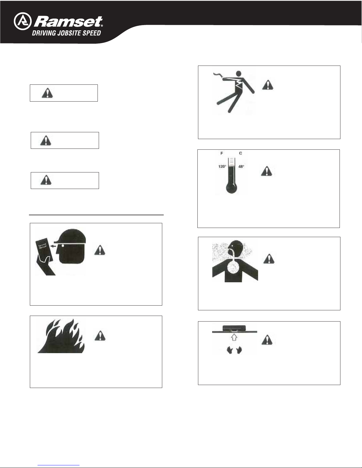
CHEMICAL/EXPLOSION HAZARD
Read ALL instructions before charging or using
the battery. Failure to follow ALL instructions may
result in fire, severe burns and/or release of toxic
materials.
DANGER
DANGER
EXPLOSION/FIRE HAZARD
Read all safety instructions before using or handling the
fuel cell. Failure to follow ALL instructions may result in
explosion or fire. This may cause severe personal injury
or property damage. Keep the fuel cell away from heat,
sparks and open flame. Do not puncture or attempt to
open the fuel cell; it is non-refillable. Do not incinerate,
reclaim or recycle the fuel cell. Exposure to temperature
above 120 degrees F (48 degrees C) may cause the fuel
cell to burst, releasing flammable gas. Do not smoke
while installing/operating the metering valve. Never
spray toward the face or eyes. Do not inhale the spray.
Keep out of the reach of children. Store fuel cell(s) in
well ventilated areas only.
Nickel Cadmium Rechargeable Battery.
Must be recycled or disposed of prop-
erly. NOTE: DEAD BATTERY MUST BE
RETURNED TO YOUR LOCAL TRAKFAST
DISTRIBUTOR FOR PROPER DISPOSAL.
WARNING

TRAKFAST REPAIR MANUAL
6
Rev. 09/07
TOOL OPERATION
OVERVIEW
Magazine Assembly
The magazine assembly has two functions. Its primary func-
tion is to store and feed fasteners into the nose of the tool.
Its secondary function is to house the battery and battery
contact assembly.
Motor Assembly
The motor assembly is made up of components that:
• Control the piston assembly
• Control intake of the fuel/air mixture
• Vent exhaust gases
This assembly generates and controls forces that drive
the fasteners. It will require the majority of routine service
and/or repair.
• Piston Assembly
• O-Rings
Handle Assembly
The handle assembly contains electrical components, and
the fan motor and fan. The electrical components provide
spark for combustion. The fan mixes fuel with air and also
cools the motor.
Cover and
Filters
Fuel Cell
Compartment
Battery LED
Indicator Light
(opposite side) HANDLE ASSEMBLY
MAGAZINE ASSEMBLY
Magazine
Locking Knob
Trigger
Battery Compartment
(opposite side)
Follower Release
Lever
Follower
Lockout Bar
Nose
Motor
Housing
MOTOR ASSEMBLY

TRAKFAST REPAIR MANUAL
7
Rev. 09/07
TOOL OPERATION
START and PRE-COMBUSTION
When lower probe (E) is pressed against the work
surface, cage (F) is forced against the spring (G).
Combustion chamber (H) is raised up against
cylinder head (I), and O-Rings (J & M) seal off the
combustion chamber, creating an air tight seal.
This initial movement, pressing the lower probe
against the work surface, causes the fuel cell/meter-
ing valve assembly to pivot. This meters a precise
amount of fuel through the cylinder head and into
the combustion chamber cavity (K).
As the combustion chamber is raised, fan/enable
switch (L) is depressed and the chamber lockout
bar is moved out of the way of the cam. The fan
starts and mixes air with a metered amount of fuel
to provide a combustible mixture.
The chamber lockout bar prevents the trigger from
being activated until the lower probe is pressed
against the work piece, raising the combustion
chamber.

TRAKFAST REPAIR MANUAL
8
Rev. 09/07
Combustion
Depressing the trigger activates the ignition circuit.
This causes a spark (N) to jump the gap between
the spark element and cylinder head, igniting the
fuel/air mixture in the combustion chamber. Pis-
ton assembly (O) is forced downward driving the
fastener into the work surface.
TOOL OPERATION

TRAKFAST REPAIR MANUAL
9
Rev. 09/07
TOOL OPERATION
Power/Exhaust
Downward movement of the piston assembly, past
exhaust ports (P), allows exhaust gases to exit.
The pressure of the exhaust gases against the flat
washer compresses the wave washers, allowing the
gases to flow through the mid-check area (Q) and
out of the tool through the exhaust ports in the bot-
tom of the housing (R).
At the bottom of stroke, the piston assembly strikes
bumper (S).

TRAKFAST REPAIR MANUAL
10
Rev. 09/07
TOOL OPERATION
Return
Reduced pressure within the combustion chamber
allows wave washers (T) to reseal the combustion
chamber.
Rapid cooling of gases trapped in the combustion
chamber (U) creates vacuum.
This vacuum is strong enough to lift and hold the pis-
ton assembly in its starting position. As the piston as-
sembly moves up the sleeve, air is drawn in through
ports in the housing nose (V).

TRAKFAST REPAIR MANUAL
11
Rev. 09/07
TOOL OPERATION
Purging
The combustion chamber drops when the tool is
lifted from the work surface and the trigger is re-
leased. This opens the seal between the combustion
chamber and cylinder head O-Ring (W) and sleeve
O-Ring (X).
The fan is now able to circulate fresh air into the
combustion chamber, cooling the sleeve (Y) and
purging any remaining exhaust gases from the tool
through ports (Z).

TRAKFAST REPAIR MANUAL
12
Rev. 09/07
TROUBLESHOOTING
SYMPTOM POSSIBLE PROBLEMS SERVICE
Battery Cell doesn’t appear to ac-
cept charge — green Charger light
does not come on — red Charger
light comes on when Battery Cell is
inserted in Charger.
Inoperative indicator lights on Char-
ger.
Try Battery Cell in tool after charge
cycle. If tool LED is green, Charger
lights are not working properly.
Replace Charger or monitor charg-
ing time to ensure Battery Cell has
adequate time for recharging. If tool
LED is red or is off, check Charger
output voltage.
Battery Cell damaged or cycle life
exhausted.
Replace Battery Cell.
Battery is inserted into Charger and
no red LED.
Check power to Charger. Rotate Battery Cell in Charger holding
red button down until red light comes
on.
Battery Charger lights flash red/green. Battery Cell left in completely dis-
charged state for extensive time.
Place Battery Cell in Charger for 3
hours, then try in tool. If tool LED still
indicates red, replace Battery Cell.
Battery Cell won’t fit in Charger open-
ing freely.
Battery Cell case or label is damaged. Remove raised burrs or replace label.
Do not use Battery Cell if plastic case
is cracked or severely damaged.
Blue Charger light won’t come on
when Charger is plugged in; red light
won’t come on when discharged Bat-
tery Cell is inserted.
Defective indicator light(s) and/ or
Charger.
Check Charger output voltage. Make
sure Charger is plugged into an ener-
gized 110V outlet.
Blue Charger light comes on when
Charger is plugged in; red light won’t
come on when discharged Battery
Cell in inserted.
Battery Cell not completely inserted
into Charger.
Check terminal end of battery for
burrs on tube or scuffed label. Service
as required. Replace severely dam-
aged Battery Cell.
Terminals in Charger not making
contact with Battery Cell.
Unplug Charger and check if terminals
are O.K. If not, replace Charger.
Charger gets hotter than normal,
makes excessively loud noise, or
smokes during charging cycle. Char-
ger cord or wall plug gets hotter than
normal.
Damaged Charger. Discontinue use immediately and
unplug from power source. Replace
Charger and tag. Dispose of Charger
to prevent accidental use.
Preparing Tool for Operation — Battery/Charger Problems

TRAKFAST REPAIR MANUAL
13
Rev. 09/07
TOOL DISASSEMBLY
DANGER
ALWAYS TAKE THE FOLLOWING PRECAUTIONS BEFORE ANY SERVICE OR
ROUTING MAINTENANCE IS PERFORMED:
• REMOVE FASTENERS
• REMOVE FUEL CELL
• REMOVE BATTERY
REMOVE THE MAGAZINE ASSEMBLY
Loosen and remove knob (part #801124).
Slide the magazine back and away from nose.

TRAKFAST REPAIR MANUAL
14
Rev. 09/07
TOOL DISASSEMBLY
REMOVE HANDLE ASSEMBLY (Part 1)
Lift off cap, grill and filter with screw driver.
Loosen four screws using a 5/32” hex key (Part # 7405061).
Lift off cap assembly (Part # 401365).

TRAKFAST REPAIR MANUAL
15
Rev. 09/07
Remove Screw at bottom of Handle Assembly
(Part # 7405065).
Remove Cam Bushing.(Part # 401397).
Push Cam Bushing out of Handle from
side where the Screw was removed.
REMOVE HANDLE ASSEMBLY (Part 1)

TRAKFAST REPAIR MANUAL
16
Rev. 09/07
TOOL DISASSEMBLY
REMOVE MOTOR ASSEMBLY
Pull Handle Assembly away from Motor Assembly until fan clears
combustion chamber assembly.
Do not scratch combustion chamber walls with fan blades.
Set Handle Assembly down carefully so that Fan Blades are not
damaged and Fan Motor Shaft is not bent.
When removing handle from housing, be sure not to bend fan
blades.
Be sure leads and connectors are positioned so that leads are not
pinched when installing cap.
WARNING
DO NOT operate tool until all screws are tightened.
DANGER
NEVER attempt to operate tool without cap assembly securely
fastened. Cap assembly secures cylinder head to combustion
chamber.
Operating TrakFast with cap assembly off or loose will cause burn-
ing fuel to escape through top of tool, causing burns and damage
to tool.
CAUTION

TRAKFAST REPAIR MANUAL
17
Rev. 09/07
TOOL DISASSEMBLY
Motor/Cylinder Head Assembly
Torque Head Switch to 5-10 in-lbs.
Torque Spark Plug to 20-25 in-lbs.
Install Stem Adapter as illustrated.
Notice the difference between one end of the Sleeve to the other.
One side of the sleeve has a rib. The other side does not. The ribs
should be to the inside and should touch the fan motor.
**CRITICAL**
Install the Motor Sleeve as illustrated. Pay careful attention to the
orientation of the “split” which is pointing at the Spark Plug and
how the ends of the Motor Sleeve face each other. This process
determines how well the motor shaft will be centered after the mo-
tor is inserted.

TRAKFAST REPAIR MANUAL
18
Rev. 09/07
Apply a small amount of oil or lubricant to the inside of the bore
where the Fan Motor is positioned.
Insert Motor Assembly as illustrated.
The Motor Sleeve orientation will determine how well the spacing
will be around the shaft. Make sure that it is equally spaced all the
way around.
SOMETIMES you may have to adjust the Motor Sleeve clockwise
or counterclockwise to help center the shaft.
Motor/Cylinder Head Assembly (cont’d)

TRAKFAST REPAIR MANUAL
19
Rev. 09/07
TOOL DISASSEMBLY
Make sure the “flat” side of the shaft is where the Set Screw on
the Fan Blade will be tightened.
Position the Fan Blade approximately .120” away from the bottom
of the cylinder head. Feeler Gages or an 1/8” drill bit works well as
a spacer.
Carefully place the Fan Blade until it is flat and leveled over the Fan
Blade Spacer.
Tighten Set Screw no more than 8 to 10 in-lbs of torque.
Motor/Cylinder Head Assembly (cont’d)
Other manuals for TRAKFAST
1
Table of contents
Other RAMSET Nail Gun manuals
Popular Nail Gun manuals by other brands

Worx
Worx WX840L manual

Bostitch
Bostitch 650S5 Operation and maintenance manual

Senco
Senco FinishPro 32 operating instructions

Lumberjack
Lumberjack TAC18G Safety and operating manual

Aircat
Aircat 807 Operating instructions, parts list & warranty

Central Pneumatic
Central Pneumatic 68019 Set up and operating instructions