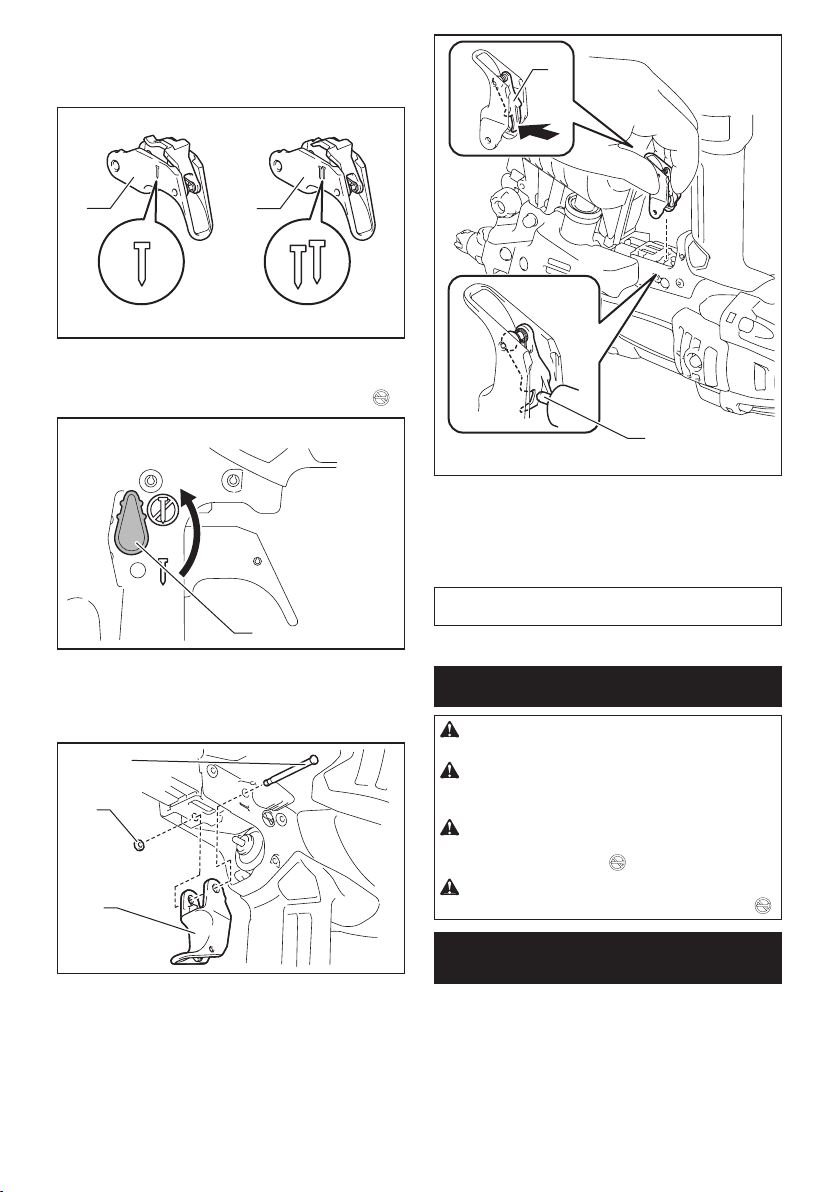
Makita AN935H User manual

INSTRUCTION MANUAL
MANUEL D'INSTRUCTION
MANUAL DE INSTRUCCIONES
Construction Coil Nailer
Pistolet Cloueur
Clavadora Neumática de Carrete
AN935H
IMPORTANT: Read Before Using.
IMPORTANT : Lire avant usage.
IMPORTANTE: Lea antes de usar.

2ENGLISH
ENGLISH (Original instructions)
SPECIFICATIONS
Model: AN935H
Air pressure 1.28 - 2.26 MPa (180 - 320 PSIG)
Nail length Wire-collated coil nail 45 mm - 90 mm (1-3/4″ - 3-1/2″)
Sheet-collated coil nail 45 mm - 75 mm (1-3/4″ - 3″)
Nail capacity Wire-collated coil nail 120 pcs - 300 pcs
Sheet-collated coil nail 200 pcs
Minimum hose diameter 4.0 mm (5/32″)
Dimensions (L x W x H) 299 mm x 125 mm x 330 mm
(11-3/4″ x 4-7/8″ x 13″)
Net weight 2.7 kg (6.0 lbs)
• Due to our continuing program of research and development, the specications herein are subject to change
without notice.
• Specications may differ from country to country.
• Weight according to EPTA-Procedure 01/2003
SAFETY WARNINGS
Important safety instructions
For personal safety and proper operation and main-
tenance of the tool, read this instruction manual
carefully before using the tool.
WARNING: WHEN USING THIS TOOL, BASIC
SAFETY PRECAUTIONS SHOULD ALWAYS BE
FOLLOWED TO REDUCE THE RISK OF PERSONAL
INJURY, INCLUDING THE FOLLOWING:
READ ALL INSTRUCTIONS.
Personal Protective Equipment
1. Always wear safety glasses to avoid eye injury
from dust or fasteners. The safety glasses should
conform with the requirements of ANSI Z87.1.
WARNING:It is an employer's responsibility
to enforce the use of safety eye protection
equipment by the tool operators and by other
persons in the immediate working area.
2. Wear hearing protection to protect your ears
against exhaust noise and head protection.
Also wear light but not loose clothing. Sleeves
should be buttoned or rolled up. No necktie
should be worn.
Flammable Atmospheres
1. Do not operate tool in explosive atmospheres,
such as in the presence of ammable liquids,
gases or combustible dust.
Tool modication
1. The tool should not be modied unless autho-
rized in the tool manual or approved in writing
by the tool manufacturer.
Tool maintenance
1. Refer to the tool maintenance instructions for
detailed information on the proper mainte-
nance of a tool.
Recommended fasteners and accessories
1. Use only fasteners made or recommended by
the tool manufacturer, or fasteners that per-
form equivalently to those recommended by
the manufacturer.
2. Use only accessories made or recommended
by the tool manufacturer, or accessories that
perform equivalently to those recommended
by the manufacturer.
Inspect tool before operating to:
1. Use only power source specied in the instruc-
tion manual.
Operate the tool within the specied air pres-
sure on the tool label for safety and longer tool
life. Do not exceed the recommended max.
operating pressure. The tool should not be
connected to a source whose pressure poten-
tially exceeds 3.39 MPa (480 PSIG).
2. Never use the tool with other than compressed
air. If bottled gas (carbon dioxide, oxygen,
nitrogen, hydrogen, air, etc.) or combustible
gas (hydrogen, propane, acetylene, etc.) is
used as a power source for this tool, the tool
will explode and cause serious injury.
3. Always check the tool for its overall condition
and loose screws before operation. Tighten as
required.
4. Make sure all safety systems are in working
order before operation. The tool must not
operate if only the trigger is pulled or if only
the contact element is pressed against the
wood. It must work only when both actions are
performed. Test for possible faulty operation
with fasteners unloaded and the contact ele-
ment in fully pulled position.
5. Always check contact element as instructed in
this manual. Fasteners may be driven acciden-
tally if the safety mechanism is not working
correctly.

3ENGLISH
Operating controls
1. Do not use a tool with missing or damaged
safety warning label(s.)
2. A tool that is not in proper working order must
not be used. Tags and physical segregation
shall be used for control.
3. Do not remove, tamper with, or otherwise
cause tool operating controls to become
inoperable.
4. Do not operate tool if any portion of the tool
operating controls is inoperable, discon-
nected, altered, or not working properly.
Tool handling
1. Only persons who have read and understand
the tool operating/safety instructions should
operate the tool.
2. Always assume that tool contains fasteners.
3. Do not point tool toward yourself or anyone
whether it contains fasteners or not.
4. Keep bystanders and children away while
operating tool.
5. Do not actuate tool unless tool is placed rmly
against the workpiece.
6. Respect tool as a working implement.
7. Do not engage in horseplay.
8. Stay alert, focus on your work and use com-
mon sense when working with tools.
9. Do not use tool while tired, after having con-
sumed drugs or alcohol, or while under the
inuence of medication.
10. Do not overreach. Keep proper footing and
balance at all times.
11.
Do not hold or carry tool with a nger on the trigger.
12. Drive fasteners into proper work surface only.
13. Do not drive fasteners into other fasteners.
14. After driving a fastener, tool may spring back
(“recoil”) causing it to move away from the
work surface. To reduce risk of injury always
manage recoil by:
a) always maintaining control of tool.
b) allowing recoil to move tool away from
work surface.
c)
not resisting recoil such that tool will
be forced back into the work surface. In
“Contact Actuation Mode,” if workpiece
contact is allowed to re-contact work sur-
face before the trigger is released, an unin-
tended discharge of a fastener will occur.
d)
keeping face and body parts away from tool.
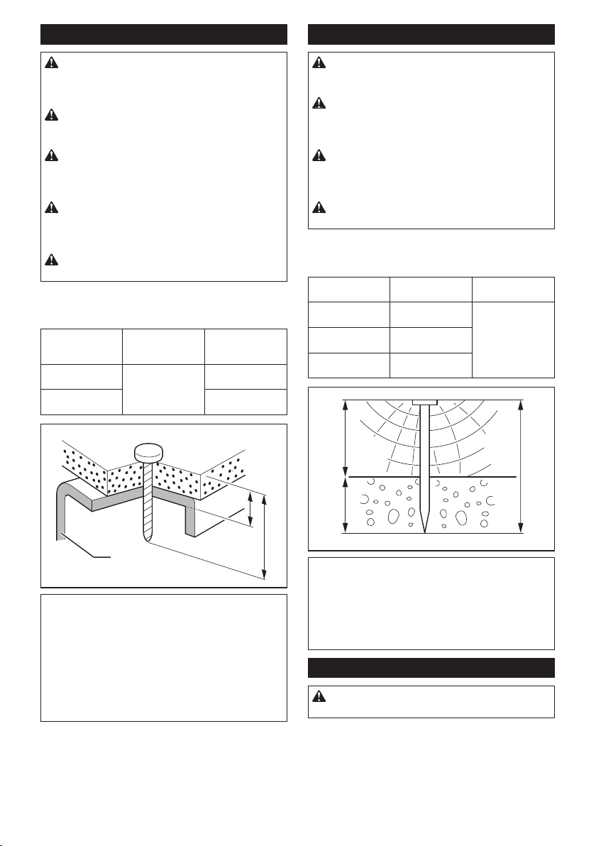
15. When working close to an edge of a workpiece
or at steep angles use care to minimize chip-
ping, splitting or splintering, or free ight or
ricochet of fasteners, which may cause injury.
16. Keep hands and body away from fastener
discharge area of tool.
17. Do not load tool with fasteners when any one
of the operating controls is activated.
18. Do not operate tool with any power source
other than that specied in tool operating/
safety instructions.
19. Do not operate tool with any operating pres-
sure other than that specied in tool operating/
safety instructions.
20. Always select an actuation system that is
appropriate to the fastener application and the
training of the operator.
21. Use extra caution when driving fasteners into
existing walls or other blind areas to prevent
contact with hidden objects or persons on
other side (e.g., wires, pipes.)
22. Do not lift, pull or lower tool by the hose.
Disconnecting tool
Disconnect tool from the power source when:
1. Not in use;
2. Performing any maintenance or repairs;
3. Clearing a jam;
4. Elevating, lowering or otherwise moving the
tool to a new location;
5. Tool is outside of the operator’s supervision or
control; or
6. Removing fasteners from the magazine.
Additional safety instructions
1. The area should be sufciently illuminated to
assure safe operations. The area should be
clear and litter-free.
2. There may be local regulations concerning
noise which must be complied with by keeping
noise levels within prescribed limits. In certain
cases, shutters should be used to contain
noise.
3. Check walls, ceilings, oors, roong and
the like carefully to avoid possible electrical
shock, gas leakage, explosions, etc. caused by
striking live wires, conduits or gas pipes.
4. On rooftops and other high locations, drive
fasteners as you move forward. It is easy to
lose your footing if you drive fasteners while
inching backward. When driving against per-
pendicular surface, drive fasteners from the
top to the bottom. You can perform the opera-
tions with less fatigue by doing so.
5. Do not leave the loaded tool or the air com-
pressor under pressure for a long time out in
the sun. Be sure that dust, sand, chips and
foreign matter will not enter the tool in the
place where you leave it setting.
6. Perform cleaning and maintenance right after
nishing the job. Keep the tool in tip-top condi-
tion. Lubricate moving parts to prevent rusting
and minimize friction-related wear. Wipe off all
dust from the parts.
7. Do not disconnect the air hose with a nger
on the trigger. An unexpected driving will cause
serious injury when the air hose is connected.
8. When you drop or strike the tool, check the
tool damage or crack and make sure that
safety systems are in working order before
operation. As there is high pressure inside the
tool, failure to do so will cause serious injury.
9. Ask Makita's Authorized service centers for
periodical inspection of the tool.
10. To maintain product SAFETY and RELIABILITY,
maintenance and repairs should be performed
by Makita Authorized or Factory Service
Centers, always using Makita replacement
parts.
SAVE THESE INSTRUCTIONS.

4ENGLISH
WARNING: MISUSE or failure to follow the
safety rules stated in this instruction manual may
cause serious personal injury.
Symbols
The followings show the symbols used for tool.
Read and understand tool labels and man-
ual. Failure to follow warnings could result
in death or serious injury.
Operators and others in work area must
wear safety glasses with side shields.
Keep ngers away from trigger when
not driving fasteners to avoid accidental
discharge.
PARTS DESCRIPTION
1
2
3
4
5
► 1. Trigger 2. Trigger lock lever 3. Hook 4. Magazine
cap 5. Nose adapter (contact element)
INSTALLATION
Selecting compressor
0102030405
06
0
0
1
2
3
5
6
4
3.5
1
2
4
5
3
1. Nailing frequency (times/min) 2. Compressor air out-
put per minute (CFM (ft3/min.)) 3. 2.26 MPa (320 PSIG)
4. 1.77 MPa (250 PSIG) 5. 1.28 MPa (180 PSIG)
The air compressor must comply with the requirements
of ANSI B19.3.
Select a compressor that has ample pressure and air
output to assure cost-efcient operation. The graph
shows the relation between nailing frequency, applica-
ble pressure and compressor air output.
Thus, for example, if nailing takes place at a rate of
approximately 40 times per minute at a compression of
1.77 MPa (250 PSIG), a compressor with an air output
over 3.5 CFM ( ft3/minute) is required.
Pressure regulators must be used to limit air pressure to
the rated pressure of the tool where air supply pressure
exceeds the tool’s rated pressure. Failure to do so may
result in serious injury to tool operator or persons in the
vicinity.
Selecting air hose
CAUTION: Low air output of the compressor,
or a long or smaller diameter air hose in relation
to the nailing frequency may cause a decrease in
the driving capability of the tool.

5ENGLISH
Use a high pressure resistant air hose.
Use an air hose as large and as short as possible to
assure continuous, efcient nailing operation.
Lubrication
1
► 1. Pneumatic tool oil
Oil the tool with pneumatic tool oil by placing two or
three drops into the air tting. This should be done
before and after use.
For proper lubrication, the tool must be red a couple of
times after pneumatic tool oil is introduced.
FUNCTIONAL
DESCRIPTION
CAUTION: Before adjusting or checking func-
tion on the tool, always lock the trigger by turning
the trigger lock lever to the lock position , and
disconnect the air hose from the tool.
Adjusting depth of nailing
This toll has the adjuster of the nailing depth. To mod-
ulate the nailing depth, turn the adjuster to the proper
depth.
1
► 1. Adjuster
The adjustable range is 8.5 mm (11/32"). (One full turn
allows 1.25 mm (1/16") adjustment.)
123
► 1. Too deep 2. Flush 3. Too shallow
Hook
CAUTION: Always disconnect the hose when
hanging the tool using the hook.
CAUTION: Never hook the tool at high loca-
tion or on potentially unstable surface.
CAUTION: Do not hang the hook from the
waist belt. If the nailer accidentally drops, it may
result in misring and personal injuries.
The hook is useful for hanging up the tool temporarily.
The hook can be turned while pushing the bottom to the
desired angle.
1
► 1. Hook
Furthermore, this hook can be installed on either side
of the tool.
To change the installation position, remove the bolt with
a hex wrench. Install the hook on another side and then
secure it rmly with the bolt.

6ENGLISH
2
1
► 1. Hook 2. Bolt
Nose adapter
To prevent the surface of workpiece from being
scratched or damaged, use the nose adapter.
To detach the nose adapter from its housing base, pull
the nose adapter in the direction of the arrow.
1
► 1. Nose adapter
To attach the nose adapter to the contact element,
press it onto the contact element until the recessed
parts in four places inside the nose adapter t in four
protrusions of the contact element.
3
2
14
► 1. Nose adapter 2. Contact element 3. Protrusion
4. Recessed part
Air duster
CAUTION: Do not aim the ejection port of the
air duster to someone. Also, keep your hands and
foot away from the ejection port. If the air duster
button is accidentally pushed, it may cause a per-
sonal injury.
CAUTION: Always check your surroundings
before using the air duster. Blown dust or objects
may hit someone.
CAUTION: Do not connect or disconnect the
air hose while pushing the air duster button.
The air supplied to the tool can also be used as an air
duster. You can clean the work area by pressing the
button on the grip end.
1
► 1. Button
NOTICE: After using the air duster, the driving force
of the tool will temporarily decline. Wait until the air
pressure recovers in this case.
NOTICE: Perform a test blow if you use the air
duster immediately after the oil was applied. The oil
may be sprayed with the air.
ASSEMBLY
CAUTION: Before carrying out any work on
the tool, always lock the trigger by turning the
trigger lock lever to the lock position , and
disconnect the air hose from the tool.
Loading nailer
CAUTION: Do not use deformed nails or
linked sheet.
1. Disconnect the air hose.
2. Depress the latch lever and open the door and
magazine cap.

7ENGLISH
1
2
3
► 1. Latch lever 2. Door 3. Magazine cap
3. Turn the adjust shaft and set the step of the
change plate suitable for the nail length. Make sure that
the arrow points to the corresponding graduation incre-
ment of the nail length marked on the adjust shaft.
1
2
3
► 1. Change plate 2. Adjust shaft 3. Arrow
NOTICE: If the tool is operated with the change
plate set to the wrong step, it may result in poor nail
feeding or tool malfunction.
4. Place the nail coil over the change plate and
uncoil enough nails to reach the nail rail.
Then place the rst nail in the nail rail and the second
nail in the feed claw. Also, place other uncoiled nails on
feeder body.
1
2
► 1. Nail rail 2. Feed claw
5. Check that the nail coil is set properly in the
magazine.
6. Close the magazine cap carefully. Then with
depressing the latch lever, close the door until the latch
lever locks.
Connecting air hose
CAUTION: Do not connect the air hose with
a nger on the trigger. An unexpected driving will
cause serious injury.
12
► 1. Air tting 2. Air socket
Slip the air socket of the air hose onto the air tting on
the nailer. Be sure that the air socket locks rmly into
position when installed onto the air tting.
A hose coupling must be installed on or near the tool in
such a way that the pressure reservoir will discharge at
the time the air supply coupling is disconnected.
Changing the trigger for contact
actuation mode
CAUTION: Always disconnect the air hose
and unload the tool with nails before replacing
the trigger.
CAUTION: After the trigger replacement,
always check that the tool operates properly
before actual work. Do not load the tool with any
nails before checking the function to avoid unex-
pected nailing.

8ENGLISH
The trigger for single sequential actuation mode is
factory-installed. To change the nailing mode to contact
actuation, replace the trigger part with the one for con-
tact actuation.
12
► 1. Trigger for single sequential actuation (Gray
color) 2. Trigger for contact actuation (Black color)
1. Turn the trigger lock lever to the lock position .
1
► 1. Trigger lock lever
2. Push the pin securing the trigger from the ure-
thane washer side, and then remove the urethane
washer. Then pull out the pin and remove the trigger.
1
2
3
► 1. Pin 2. Urethane washer 3. Trigger
3. Set the trigger assembly for contact actuation.
With pushing in the hinged part inward, set the trigger
so that the hinged part is under the rod of the valve in
the housing.
2
1
► 1. Hinged part 2. Rod of the valve
4.
Insert the pin to the hole and secure it by urethane washer.
5. Connect the air hose, and make sure that the
tool operates properly. Refer to the section “Checking
proper action before operation”.
NOTE: To set back to single sequential actuation,
follow the procedures for changing the trigger above.
OPERATION
CAUTION: Make sure all safety systems are in
working order before operation.
CAUTION: When operating the tool, do not
close the face to the tool. Also keep hands and
feet away from the ejection port area.
CAUTION: When not operating the tool,
always lock the trigger by turning the trigger lock
lever to the lock position .
CAUTION:
Make sure that the trigger is locked
when the trigger lock lever is set to the lock position .
Checking proper action before
operation
Before operation, always check following points.
— Make sure that the tool does not operate only by
connecting the air hose.
— Make sure that the tool does not operate only by
pulling the trigger.
— Make sure that the tool does not operate only by
placing the contact element against the workpiece
without pulling the trigger.

9ENGLISH
1
2
3
► 1. Contact element 2. Workpiece 3. Trigger (not
pulled)
— In single sequential actuation mode, make sure
that the tool does not operate when pulling the
trigger rst and then placing the contact element
against the workpiece.
1
2
Nailing method
To prevent the trigger from being accidentally pulled,
the trigger lock lever is provided.
To lock the trigger, turn the trigger lock lever to the lock
position .
To use the tool, turn the trigger lock lever to the unlock
position .
11
22
► 1. Trigger lock lever 2. Trigger
Single sequential actuation
Place the contact element against the workpiece and
pull the trigger fully.
After nailing, release the contact element, and then
release the trigger.
1
2
CAUTION: Do not place the contact element
against the workpiece with excessive force. Also,
pull the trigger fully and hold it on for 1-2 seconds
after nailing.
Even in the “Single sequential actuation” mode, half-
pulled trigger causes an unexpected nailing, when the
contact element re-contacts the workpiece.
Contact actuation
Pull the trigger rst and then place the contact element
against the workpiece.
2
1

10 ENGLISH
Nailing on steel plate
WARNING: When nailing on the C-shaped
steel, limit the thickness to 3.2 mm (1/8") or thin-
ner. Otherwise the tool will bounce severely and a
nail struck back, causing serious injuries.
WARNING: Use hardened nails only for steel
plate. Using other purposed nails may cause serious
injuries.
WARNING: When nailing, hold the tool so that
it stands upright to the driving surface. Slanted
nailing may cause nails to strike back, causing seri-
ous injuries.
WARNING: Do not use the tool for fastening
a corrugated plate or the C-shaped steel directly.
It may cause nails to strike back, causing serious
injuries.
WARNING: Do not use the tool for nailing on
ceiling or roof.
Choose and use nails 10 mm (3/8") or much longer than
total thickness of all workpiece to be fastened. Refer to
the table below.
Material thick-
ness including
C-shaped steel (A)
C-shaped steel (B)
thickness
Nail length (C)
30 mm - 35 mm
(1-3/16" - 1-3/8")
1.6 mm - 3.2 mm
(1/16" - 1/8")
45 mm (1-3/4")
35 mm - 40 mm
(1-3/8" - 1-5/8")
50 mm (2")
A
C
B
NOTICE: Depending on the hardness and
total thickness of all workpiece in combination,
enough fastening may not be obtained. Nailing on
steel plate with excessive depth may extremely
reduce the fastening force. Before nailing, adjust
the nailing depth properly.
NOTICE: Nailing on the steel plate makes the
driver prematurely worn out and it may cause nail
jamming. When the driver is worn, replace it with a
new one.
Nailing on concrete
WARNING: Use hardened nails only for con-
crete. Using other purposed nails may cause serious
injuries.
WARNING: Do not nail directly on the con-
crete or do not fasten directly the steel plate to
the concrete. It may cause concrete fragments to y
off or nails to strike back, causing serious injuries.
WARNING: When nailing, hold the tool so that
it stands upright to the driving surface. Slanted
nailing may cause concrete fragments to y off or
nails to strike back, causing serious injuries.
WARNING: Do not use the tool for fastening
an object to hang something such as sewer pipe.
Choose and use nails so that the penetration depth into
concrete ranges 10 mm (3/8") - 15 mm (5/8"). Refer to
the table below.
Wood thick-
ness (A)
Nail length (B) Penetration depth
into concrete (C)
30 mm - 35 mm
(1-3/16" - 1-3/8")
45 mm (1-3/4") 10 mm - 15 mm
(3/8" - 5/8")
35 mm - 40 mm
(1-3/8" - 1-5/8")
50 mm (2")
50 mm - 55 mm
(2" - 2-3/16")
65 mm (2-1/2")
B
A
C
NOTICE: Use the tool only for soft concrete
built up not so long before. Driving nails into hard
concrete may cause nail bending or nailing into insuf-
cient depth.
NOTICE: When penetrating into concrete
deeper than 15 mm (5/8"), nails may not be driven
sufciently.
Cutting linked sheet
CAUTION: Always disconnect the air hose
from the tool before removing the linked sheet.
When using linked sheet nails, the linked sheet will be
ejected from the driver guide as you drive the nails.
Tear away the ejected sheet by twisting as shown in the
gure.

11 ENGLISH
1
► 1. Ejected linked sheet
Removing jammed nails
CAUTION: Always lock the trigger by turning
the trigger lock lever to the lock position , and
disconnect the hose before removing jammed
nails. Also remove the nails from the magazine
before cleaning a jam.
1. Depress the latch lever and open the door. Open
the magazine cap and remove the nail coil.
2. Insert a small metal rod into the nail ejection port
and hit it with a hammer lightly.
1
2
3
► 1. Metal rod 2. Nail ejection port 3. Hammer
3. Remove the jammed nail with a at-blade screw-
driver or other similar tool.
4. Reset the nail coil and close the magazine cap
and the door.
MAINTENANCE
CAUTION: Before attempting to perform
inspection or maintenance, always lock the trig-
ger by turning the trigger lock lever to the lock
position , and disconnect the air hose from the
tool.
NOTICE: Never use gasoline, benzine, thinner,
alcohol or the like. Discoloration, deformation or
cracks may result.
Cleaning of tool
Iron dust that adhere to the magnet can be blown off by
using an air duster.
1
► 1. Magnet
Storage
When not in use, disconnect the hose. Then cap the air
tting with the cap. Store the nailer in a warm and dry
place.
1
► 1. Cap
Maintenance of compressor, air set
and air hose
After operation, always drain the compressor tank and
the air lter. If moisture is allowed to enter the tool,
it may result in poor performance and possible tool
failure.

12 ENGLISH
1
► 1. Drain cock
Keep the air hose away from heat (over 60°C, over
140°F), away from chemicals (thinner, strong acids or
alkalis). Also, route the hose away from obstacles which
it may become dangerously caught on during operation.
Hoses must also be directed away from sharp edges and
areas which may lead to damage or abrasion to the hose.
To maintain product SAFETY and RELIABILITY,
repairs, any other maintenance or adjustment should
be performed by Makita Authorized or Factory Service
Centers, always using Makita replacement parts.
OPTIONAL
ACCESSORIES
CAUTION: These accessories or attachments
are recommended for use with your Makita tool
specied in this manual. The use of any other
accessories or attachments might present a risk of
injury to persons. Only use accessory or attachment
for its stated purpose.
If you need any assistance for more details regard-
ing these accessories, ask your local Makita Service
Center.
• Nails
• Air hose
• Safety goggles
NOTE: Some items in the list may be included in the
tool package as standard accessories. They may
differ from country to country.
MAKITA LIMITED ONE YEAR
WARRANTY
Warranty Policy
Every Makita tool is thoroughly inspected and tested
before leaving the factory. It is warranted to be free of
defects from workmanship and materials for the period
of ONE YEAR from the date of original purchase.
Should any trouble develop during this one year period,
return the COMPLETE tool, freight prepaid, to one
of Makita’s Factory or Authorized Service Centers. If
inspection shows the trouble is caused by defective
workmanship or material, Makita will repair (or at our
option, replace) without charge.
This Warranty does not apply where:
• repairs have been made or attempted by others:
• repairs are required because of normal wear and
tear:
• the tool has been abused, misused or improperly
maintained:
• alterations have been made to the tool.
IN NO EVENT SHALL MAKITA BE LIABLE FOR ANY
INDIRECT, INCIDENTAL OR CONSEQUENTIAL
DAMAGES FROM THE SALE OR USE OF THE
PRODUCT. THIS DISCLAIMER APPLIES BOTH
DURING AND AFTER THE TERM OF THIS
WARRANTY.
MAKITA DISCLAIMS LIABILITY FOR ANY IMPLIED
WARRANTIES, INCLUDING IMPLIED WARRANTIES
OF "MERCHANTABILITY" AND "FITNESS FOR A
SPECIFIC PURPOSE," AFTER THE ONE YEAR TERM
OF THIS WARRANTY.
This Warranty gives you specic legal rights, and you
may also have other rights which vary from state to
state. Some states do not allow the exclusion or lim-
itation of incidental or consequential damages, so the
above limitation or exclusion may not apply to you.
Some states do not allow limitation on how long an
implied warranty lasts, so the above limitation may not
apply to you.

13 FRANÇAIS
FRANÇAIS (Mode d’emploi original)
SPÉCIFICATIONS
Modèle : AN935H
Pression d’air 1,28 - 2,26 MPa (180 - 320 PSIG)
Longueur de clou Clous en rouleau reliés par l
métallique
45 mm - 90 mm (1-3/4″ - 3-1/2″)
Clous en rouleau reliés en
bande
45 mm - 75 mm (1-3/4″ - 3″)
Capacité en clous Clous en rouleau reliés par l
métallique
120 pièces - 300 pièces
Clous en rouleau reliés en
bande
200 pièces
Diamètre minimum du tuyau 4,0 mm (5/32″)
Dimensions (L x P x H) 299 mm x 125 mm x 330 mm
(11-3/4″ x 4-7/8″ x 13″)
Poids net 2,7 kg (6,0 lbs)
• Étant donné l’évolution constante de notre programme de recherche et de développement, les spécications
contenues dans ce manuel sont sujettes à modication sans préavis.
• Les spécications peuvent varier suivant les pays.
• Poids conforme à la procédure EPTA du 01/2003
CONSIGNES DE
SÉCURITÉ
Consignes de sécurité importantes
Par mesure de sécurité personnelle et pour assurer une
utilisation et un entretien adéquats, veuillez lire attentive-
ment ce manuel d’instructions avant d’utiliser l’outil.
MISE EN GARDE : PAR MESURE DE SÉCURITÉ,
DES PRÉCAUTIONS DE BASE DOIVENT ÊTRE
PRISES LORS DE L’UTILISATION DE CET OUTIL,
AFIN DE RÉDUIRE LES RISQUES DE BLESSURE.
CES PRÉCAUTIONS COMPRENNENT LES
SUIVANTES :
LISEZ TOUTES LES
INSTRUCTIONS.
Équipement de protection personnelle
1. Portez toujours des lunettes de sécurité pour
éviter les blessures aux yeux au contact de
la poussière ou des xations. Les lunettes de
sécurité doivent répondre aux exigences de la
norme ANSI Z87.1.
MISE EN GARDE : L’employeur a la responsabi-
lité d’imposer le port d’un dispositif de protection
des yeux aux utilisateurs des outils et à toute
personne présente dans la zone de travail.
2. Portez une protection d’oreilles pour les
protéger contre le bruit d’échappement, et
portez un casque de sécurité. Les vêtements
portés doivent être légers et ne doivent pas
être amples. Veuillez boutonner ou rouler vos
manches. Ne portez pas de cravate.
Atmosphères inammables
1. N’utilisez pas l’outil dans les atmosphères
explosives, par exemple en présence de
liquides inammables, de gaz ou de pous-
sières combustibles.
Modication de l’outil
1. L’outil ne doit être modié que si cela est auto-
risé dans le manuel de l’outil ou approuvé par
écrit par le fabricant de l’outil.
Entretien de l’outil
1. Reportez-vous aux instructions d’entretien
de l’outil pour des informations détaillées sur
l’entretien adéquat d’un outil.
Fixations et accessoires recommandés
1. Utilisez exclusivement les xations fabriquées
ou recommandées par le fabricant de l’outil,
ou des xations qui offrent un rendement équi-
valent à celles recommandées par le fabricant.
2. Utilisez exclusivement les accessoires fabri-
qués ou recommandés par le fabricant de
l’outil, ou des accessoires qui offrent un ren-
dement équivalent à ceux recommandés par le
fabricant.
Inspectez l’outil avant de l’utiliser :
1. Utilisez uniquement la source d’alimentation
spéciée dans le manuel d’instructions.
Utilisez l’outil sans dépasser la pression d’air
spéciée sur l’étiquette de l’outil, pour votre
sécurité et pour prolonger la durée de service
de l’outil. Ne dépassez pas la pression d’utili-
sation max. recommandée. L’outil ne doit pas
être raccordé à une source dont la pression
est susceptible de dépasser 3,39 MPa (480
PSIG).

14 FRANÇAIS
2. Cet outil doit être exclusivement utilisé avec
de l’air comprimé. L’utilisation d’une bou-
teille de gaz (dioxyde de carbone, oxygène,
nitrogène, hydrogène, air, etc.) ou de gaz
combustible (hydrogène, propane, acétylène,
etc.) comme source d’alimentation de cet outil
entraînera une explosion et risque de causer
une blessure grave.
3. Avant d’utiliser l’outil, assurez-vous qu’il est
en bon état et qu’aucune de ses vis n’est des-
serrée. Le cas échéant, serrez les vis.
4. Assurez-vous que tous les dispositifs de sécu-
rité sont en état de fonctionner avant d’utiliser
l’outil. Il ne faut pas que l’outil s’active lorsque
vous appuyez uniquement sur la gâchette
ou appuyez simplement l’élément de contact
contre le bois. Il ne doit s’activer que lorsque
ces deux actions sont exécutées. Retirez les
xations de l’outil et tirez complètement l’élé-
ment de contact pour vérier l’absence de tout
vice de fonctionnement.
5. Vériez toujours l’élément de contact, tel
qu’indiqué dans ce manuel. Des xations
risquent d’être projetées par accident si le
mécanisme de sécurité ne fonctionne pas
correctement.
Commandes
1. N’utilisez pas un outil dont des étiquettes de
mise en garde sont manquantes et abîmées.
2. Un outil qui n’est pas en bon état de marche
ne doit pas être utilisé. Des balises et la
séparation matérielle seront utilisées pour la
commande.
3. Ne retirez pas, ne modiez pas et ne rendez
d’aucune façon les commandes inutilisables.
4. N’utilisez pas l’outil si toute partie des com-
mandes de l’outil est inutilisable, déconnectée,
altérée ou défectueuse.
Manipulation de l’outil
1. L’outil ne doit être utilisé que par des per-
sonnes qui ont lu et compris les instructions
d’utilisation et consignes de sécurité.
2. Supposez toujours que l’outil contient des
xations.
3. Ne pointez pas l’outil vers vous-même ou toute
autre personne, peu importe qu’il contienne ou
non des xations.
4. Ne laissez pas approcher les curieux et les
enfants pendant que vous utilisez l’outil.
5. N’activez l’outil que s’il est fermement placé
contre la pièce à travailler.
6.
Respectez l’outil en tant qu’instrument de travail.
7. Évitez tout chahut.
8. Restez alerte, attentif à votre travail et faites
preuve de bon sens lorsque vous utilisez des
outils.
9. N’utilisez pas l’outil si vous êtes fatigué, avez
consommé une drogue ou de l’alcool, ou êtes
sous l’effet de médicaments.
10. Ne vous étirez pas trop. Assurez-vous d’une
bonne prise au sol et d’un bon équilibre en
tout temps.
11. Évitez de tenir ou de transporter l’outil avec un
doigt sur la gâchette.
12. Ne posez les xations que sur une surface à
travailler adéquate.
13. Ne posez pas de xations dans d’autres
xations.
14. Après la pose d’une xation, il se peut que l’ef-
fet de ressort (« recul ») de l’outil l’éloigne de
la surface à travailler. Pour réduire les risques
de blessure, contrôlez toujours le recul en :
a) gardant constamment la maîtrise de
l’outil;
b) laissant le recul éloigner l’outil de la
surface à travailler;
c) ne résistant pas au recul, an de ne pas
forcer le retour de l’outil sur la surface
à travailler. En « Mode de commande
par contact », une xation sera libérée
involontairement si vous laissez l’outil
retoucher la surface à travailler avant la
libération de la gâchette.
d) gardant le visage et autres parties du
corps à l’écart de l’outil.
15. Lorsque vous travaillez près du bord d’une
pièce à travailler ou sur des angles prononcés,
faites-le prudemment pour réduire les risques
d’écaillage, de fendillement ou d’éclatement,
ou pour éviter que les xations ne s’envolent
librement ou ricochent, ce qui peut causer des
blessures.
16. Gardez les mains et le corps à l’écart de la
zone de libération des xations.
17. Ne mettez pas de xations dans l’outil pendant
que toute commande est activée.
18. Ne faites fonctionner l’outil avec aucune autre
source d’alimentation que celle spéciée dans
les instructions d’utilisation et consignes de
sécurité de l’outil.
19. Ne faites fonctionner l’outil avec aucune autre
pression d’utilisation que celle spéciée dans
les instructions d’utilisation et consignes de
sécurité de l’outil.
20. Sélectionnez toujours un système de com-
mande qui convient à l’application de xation
et à la formation reçue par l’utilisateur.
21. Soyez tout particulièrement prudent lorsque
vous posez des xations dans des cloisons
existantes ou tout autre matériau dont l’arrière
n’est pas visible, pour éviter le contact avec
des objets dissimulés (p. ex., des câbles ou
tuyaux) ou avec des personnes se trouvant de
l’autre côté.
22. Évitez de soulever, tirer ou abaisser l’outil par
le tuyau.
Débranchement de l’outil
Débranchez l’outil de la source d’alimentation
lorsque :
1. non utilisé;
2. exécution de tout entretien ou réparation;
3. nettoyage d’un blocage;
4. élévation, abaissement ou déplacement de
l’outil vers un nouvel emplacement;
5. outil non surveillé ou contrôlé par l’utilisa-
teur; ou
6. retrait des xations du magasin.

15 FRANÇAIS
Consignes de sécurité supplémentaires
1. La zone doit être sufsamment éclairée pour
assurer un travail sécuritaire. La zone doit être
dégagée et sans déchets.
2. Il se peut que des réglementations locales
s’appliquent concernant les niveaux de bruit
permis. Veuillez les respecter. Le cas échéant,
des volets doivent être installés pour réduire le
bruit.
3. Pour éviter tout risque de choc électrique, de
fuite de gaz, d’explosion, etc., provoqué par le
contact avec des ls dénudés, des conduites
ou des tuyaux de gaz, vériez le mur ou le
plafond, le plancher, le toit, etc.
4. Sur les toits et autres endroits élevés, posez
les xations en vous déplaçant vers l’avant.
Vous risquez de perdre pied si vous posez
les xations en vous déplaçant à reculons.
Lorsque vous posez des xations sur une
surface verticale, faites-le du haut vers le bas.
De cette façon le travail sera moins exigeant
physiquement.
5. N’abandonnez pas pour une période prolon-
gée un outil chargé ou un compresseur d’air
sous pression exposé au soleil à l’extérieur.
Assurez-vous de toujours déposer l’outil
en un endroit où la poussière, le sable, les
copeaux et corps étrangers ne risquent pas
d’y pénétrer.
6. Procédez au nettoyage et à l’entretien de l’outil
une fois le travail terminé. Maintenez l’outil
en excellente condition. Lubriez les pièces
mobiles pour éviter qu’elles ne rouillent et
pour limiter l’usure entraînée par la friction.
Retirez toute poussière déposée sur les
pièces.
7. Ne déconnectez pas le tuyau d’air avec un
doigt posé sur la gâchette. Le déclenchement
accidentel causerait une grave blessure au
moment du raccordement du tuyau d’air.
8. Si vous échappez ou heurtez l’outil, vériez
l’absence de dommages ou ssures, et assu-
rez-vous que tous les dispositifs de sécurité
sont en état de fonctionner avant d’utiliser
l’outil. Comme la pression est élevée à l’intérieur
de l’outil, la négligence de cette consigne risque
de causer une blessure grave.
9. Conez régulièrement l’outil à un centre de
service après-vente agréé Makita pour une
inspection.
10. Pour maintenir la SÉCURITÉ et la FIABILITÉ de
l’outil, son entretien et sa réparation doivent
être effectués dans un centre de service après-
vente agréé ou d’usine Makita, exclusivement
avec des pièces de rechange Makita.
CONSERVEZ CE MODE
D’EMPLOI.
MISE EN GARDE : Une MAUVAISE
UTILISATION de l’outil ou l’ignorance des
consignes de sécurité du présent manuel d’ins-
tructions peuvent entraîner une grave blessure.
Symboles
Les symboles utilisés pour l’outil sont indiqués
ci-dessous.
Veuillez lire et comprendre les étiquettes et
le manuel de l’outil. L’ignorance des mises
en garde peut entraîner le décès ou une
grave blessure.
L’utilisateur et toute personne présente
dans la zone de travail doivent porter
des lunettes de sécurité avec protecteurs
latéraux.
Gardez les doigts à l’écart de la gâchette
lorsque vous ne posez pas de xations,
pour éviter la libération accidentelle de
xations.
DESCRIPTION DES
PIÈCES
1
2
3
4
5
► 1. Gâchette 2. Levier de verrouillage de la gâchette
3. Crochet 4. Bouchon du magasin 5. Adaptateur de
bec (élément de contact)

16 FRANÇAIS
POSE
Sélection du compresseur
0102030405
06
0
0
1
2
3
5
6
4
3,5
1
2
4
5
3
1. Fréquence de clouage (fois/min) 2. Sortie d’air du
compresseur par minute (CFM (ft3/min)) 3. 2,26 MPa
(320 PSIG) 4. 1,77 MPa (250 PSIG) 5. 1,28 MPa (180
PSIG)
Le compresseur d’air doit répondre aux exigences de la
norme ANSI B19.3.
Choisissez un compresseur dont la capacité de pres-
surisation et de sortie d’air assurera un bon rapport
qualité/coût. Le graphique indique la relation entre la
fréquence de clouage, la pression applicable et la sortie
d’air du compresseur.
Par exemple, pour clouer environ 40 fois par minute
avec une compression de 1,77 MPa (250 PSIG), il fau-
dra un compresseur dont la sortie d’air est supérieure à
3,5 CFM (ft3/min).
Un régulateur de pression doit être utilisé pour limiter
la pression d’air à la pression nominale de l’outil là où
la pression d’air fournie dépasse la capacité nominale
de l’outil. Autrement, l’utilisateur et les personnes pré-
sentes courent un risque de blessure grave.
Sélection du tuyau d’air
ATTENTION : La capacité d’entraînement
de l’outil risque de diminuer si la sortie d’air du
compresseur est faible ou si le tuyau d’air est trop
long ou d’un diamètre trop petit pour la fréquence
de clouage.
Utilisez un tuyau d’air résistant aux pressions élevées.
Pour assurer un travail de clouage continu et efcace,
le tuyau d’air utilisé doit être le plus gros et le plus court
possible.
Lubrication
1
► 1. Huile pour outil pneumatique
Lubriez l’outil à l’aide d’huile pour outil pneumatique en
introduisant deux ou trois gouttes dans le raccord d’air.
Cela doit être fait avant et après l’utilisation.
Pour assurer une bonne lubrication, il faut faire déclen-
cher l’outil à quelques reprises après avoir introduit
l’huile pour outil pneumatique.
DESCRIPTION DU
FONCTIONNEMENT
ATTENTION : Avant d’ajuster ou de vérier le
fonctionnement de l’outil, verrouillez toujours la
gâchette en tournant le levier de verrouillage de la
gâchette sur la position verrouillée , et décon-
nectez le tuyau d’air de l’outil.
Ajustement de la profondeur de
clouage
Cet outil est doté d’un dispositif de réglage de la profon-
deur de clouage. Pour ajuster la profondeur de clouage,
tournez le dispositif de réglage sur la profondeur
adéquate.

17 FRANÇAIS
1
► 1. Régleur
La plage de réglage est de 8,5 mm (11/32″). (Un tour
complet permet un ajustement de 1,25 mm (1/16″).)
123
► 1. Trop profond 2. Au même niveau 3. Pas assez
profond
Crochet
ATTENTION : Débranchez toujours le tuyau
avant d’accrocher l’outil avec le crochet.
ATTENTION : N’accrochez jamais l’outil dans
un emplacement élevé ou sur une surface poten-
tiellement instable.
ATTENTION : N’accrochez pas l’outil à un
ceinturon. Si la cloueuse est échappée accidentelle-
ment, elle risque de se déclencher et de causer des
blessures.
Le crochet est pratique pour accrocher l’outil
temporairement.
Le crochet peut être tourné tout en poussant le bas
jusqu’à l’angle désiré.
1
► 1. Crochet
De plus, ce crochet s’installe d’un côté comme de
l’autre de l’outil.
Pour modier la position d’installation, retirez le boulon
à l’aide d’une clé hexagonale. Installez le crochet de
l’autre côté puis xez-le fermement avec le boulon.
2
1
► 1. Crochet 2. Boulon
Adaptateur de bec
Pour éviter de rayer ou d’abîmer la surface de la pièce à
travailler, utilisez l’adaptateur de bec.
Pour détacher l’adaptateur de bec de sa base de loge-
ment, tirez l’adaptateur de bec dans le sens de la èche.
1
► 1. Adaptateur de bec
Pour xer l’adaptateur de bec à l’élément de contact,
appuyez-le contre l’élément de contact jusqu’à ce que
les creux, en quatre emplacements à l’intérieur de
l’adaptateur de bec, s’adaptent aux quatre saillies de
l’élément de contact.

18 FRANÇAIS
3
2
14
► 1. Adaptateur de bec 2. Élément de contact
3. Saillie 4. Creux
Dispositif de dépoussiérage
ATTENTION : Ne pointez vers personne la
sortie d’éjection du dispositif de dépoussiérage.
Gardez aussi vos mains et pieds à l’écart de la
sortie d’éjection. Une pression accidentelle sur le
bouton du dispositif de dépoussiérage peut entraîner
une blessure.
ATTENTION : Vériez toujours les environs
avant d’utiliser le dispositif de dépoussiérage.
Les poussières ou objets soufés peuvent frapper
quelqu’un.
ATTENTION : Évitez de connecter ou décon-
necter le tuyau d’air tout en appuyant sur le bou-
ton du dispositif de dépoussiérage.
L’air fourni à l’outil peut aussi être utilisé comme dispo-
sitif de dépoussiérage. Vous pouvez nettoyer la zone
de travail en appuyant sur le bouton à l’extrémité de la
poignée.
1
► 1. Bouton
AVIS : Après l’utilisation du dispositif de dépoussié-
rage, la puissance d’entraînement de l’outil diminue
temporairement. Le cas échéant, attendez que la
pression d’air se rétablisse.
AVIS : Effectuez un essai de soufage si vous uti-
lisez le dispositif de dépoussiérage immédiatement
après l’application d’huile. Il se peut que l’huile soit
vaporisée par l’air.
ASSEMBLAGE
ATTENTION : Avant d’effectuer tout travail
sur l’outil, verrouillez toujours la gâchette en
tournant le levier de verrouillage de la gâchette
sur la position verrouillée , et débranchez le
tuyau d’air de l’outil.
Chargement de la cloueuse
ATTENTION : N’utilisez pas de clous défor-
més ou de bande porte-clous déformée.
1. Débranchez le tuyau d’air.
2. Abaissez le levier de fermeture et ouvrez la porte
et le bouchon du magasin.
1
2
3
► 1. Levier de fermeture 2. Porte 3. Bouchon du
magasin
3. Tournez l’arbre de réglage et réglez le pas de
la plaque de changement selon la longueur de clou.
Assurez-vous que la èche pointe vers la graduation
correspondante de longueur de clou marquée sur
l’arbre de réglage.

19 FRANÇAIS
1
2
3
► 1. Plaque de changement 2. Arbre de réglage
3. Flèche
AVIS : Si vous utilisez l’outil alors que la plaque de
changement n’est pas placée sur le bon pas, l’alimen-
tation en clous risque d’être mauvaise et l’outil risque
de mal fonctionner.
4. Placez le rouleau de clous sur la plaque de chan-
gement et déroulez assez de clous pour atteindre la
glissière de clous.
Placez ensuite le premier clou dans la glissière de
clous et le second dans la griffe d’alimentation. De plus,
placez les autres clous débobinés dans le corps du
dispositif d’alimentation.
1
2
► 1. Glissière de clous 2. Griffe d’alimentation
5. Assurez-vous que le rouleau de clous est bien
installé dans le magasin.
6. Fermez soigneusement le bouchon du magasin.
Ensuite, tout en enfonçant le levier de fermeture, fer-
mez la porte jusqu’à ce que le levier de fermeture se
verrouille.
Raccordement du tuyau d’air
ATTENTION : Ne connectez pas le tuyau d’air
avec un doigt sur la gâchette. Un clouage acciden-
tel pourrait entraîner une blessure grave.
12
► 1. Raccord d’air 2. Douille à air
Glissez la douille à air du tuyau d’air sur le raccord d’air
de la cloueuse. Assurez-vous que la douille à air est
verrouillée fermement en position lorsque vous l’instal-
lez sur le raccord d’air.
Un raccord à tuyau doit être installé sur ou près de
l’outil de sorte que le réservoir de pression se vide au
moment de la déconnexion du raccord d’alimentation
en air.
Changer de gâchette pour le mode
de commande par contact
ATTENTION : Avant de changer de gâchette,
débranchez toujours le tuyau d’air et déchargez
l’outil.
ATTENTION : Après avoir changé de
gâchette, vériez toujours le bon fonctionnement
de l’outil avant de commencer le véritable travail.
Ne chargez pas de clous dans l’outil avant d’avoir
vérié le fonctionnement, pour éviter tout clouage
accidentel.
La gâchette pour mode de commande séquentielle
simple est installée en usine. Pour mettre le mode de
clouage sur la commande par contact, remplacez la
gâchette par celle du mode de commande par contact.
12
► 1. Gâchette pour commande séquentielle simple
(couleur grise) 2. Gâchette pour commande par
contact (couleur noire)
1. Tournez le levier de verrouillage de la gâchette sur
la position verrouillée .

20 FRANÇAIS
1
► 1. Levier de verrouillage de la gâchette
2. Enfoncez la broche qui retient la gâchette du
côté de la rondelle d’uréthane, puis retirez la rondelle
d’uréthane. Retirez ensuite la broche en tirant dessus et
retirez la gâchette.
1
2
3
► 1. Broche 2. Rondelle d’uréthane 3. Gâchette
3. Installez l’ensemble gâchette pour la commande
par contact.
Tout en poussant la pièce articulée vers l’intérieur,
installez la gâchette de sorte que la pièce articulée se
trouve sous la tige de la valve dans le boîtier.
2
1
► 1. Pièce articulée 2. Tige de la valve
4. Insérez la broche dans le trou et xez-la avec la
rondelle d’uréthane.
5. Connectez le tuyau d’air, et assurez-vous que l’ou-
til fonctionne bien. Reportez-vous à la section « Vérier
le bon fonctionnement avant l’utilisation ».
NOTE : Pour revenir en mode de commande séquen-
tielle simple, suivez la procédure de changement de
gâchette ci-dessus.
UTILISATION
ATTENTION : Assurez-vous que tous les
dispositifs de sécurité sont en état de fonctionner
avant d’utiliser l’outil.
ATTENTION : Lorsque vous utilisez l’outil,
n’approchez pas le visage de l’outil. Gardez éga-
lement les mains et les pieds à l’écart de la zone
de la sortie d’éjection.
ATTENTION : Lorsque vous n’utilisez pas
l’outil, verrouillez toujours la gâchette en tournant
le levier de verrouillage de la gâchette sur la posi-
tion verrouillée .
ATTENTION : Assurez-vous que la gâchette
est verrouillée lorsque le levier de verrouillage
de la gâchette est placé sur la position verrouil-
lée .
Other manuals for AN935H
2
Table of contents
Languages:
Other Makita Nail Gun manuals

Makita
Makita AG090 User manual

Makita
Makita GN420C User manual

Makita
Makita DBN500 User manual

Makita
Makita AN451 User manual

Makita
Makita DBN500 User manual

Makita
Makita DPT353 User manual

Makita
Makita AN942 Manual

Makita
Makita AN922 User manual

Makita
Makita GF600 User manual

Makita
Makita FN001GA202 User manual

Makita
Makita XNB01 User manual

Makita
Makita AN250HC User manual

Makita
Makita AF502 User manual

Makita
Makita AN510H User manual

Makita
Makita GN900 Manual

Makita
Makita DBN500 User manual

Makita
Makita AN711H User manual

Makita
Makita PT001G User manual

Makita
Makita DBN600 User manual

Makita
Makita GF600 User manual