manuals.online logo
Brands
  1. Home
  2. •
  3. Brands
  4. •
  5. Ramsey Electronics
  6. •
  7. Antenna
  8. •
  9. Ramsey Electronics DAP25 User manual

Ramsey Electronics DAP25 User manual

Other Ramsey Electronics Antenna manuals

Ramsey Electronics WSR-ANT User guide

Ramsey Electronics

Ramsey Electronics WSR-ANT User guide

Ramsey Electronics DA-40 User manual

Ramsey Electronics

Ramsey Electronics DA-40 User manual

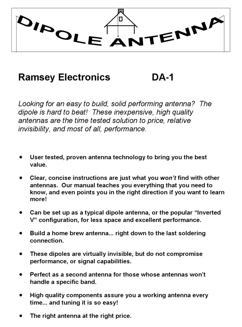
Ramsey Electronics Dipole Antenna DA-1 User guide

Ramsey Electronics

Ramsey Electronics Dipole Antenna DA-1 User guide

Ramsey Electronics AA7B User manual

Ramsey Electronics

Ramsey Electronics AA7B User manual

Ramsey Electronics The `Logi' Log Periodic Antenna LPY915 User guide

Ramsey Electronics

Ramsey Electronics The `Logi' Log Periodic Antenna LPY915 User guide

Ramsey Electronics DA-160 Mounting instructions

Ramsey Electronics

Ramsey Electronics DA-160 Mounting instructions

Ramsey Electronics AA7 User manual

Ramsey Electronics

Ramsey Electronics AA7 User manual

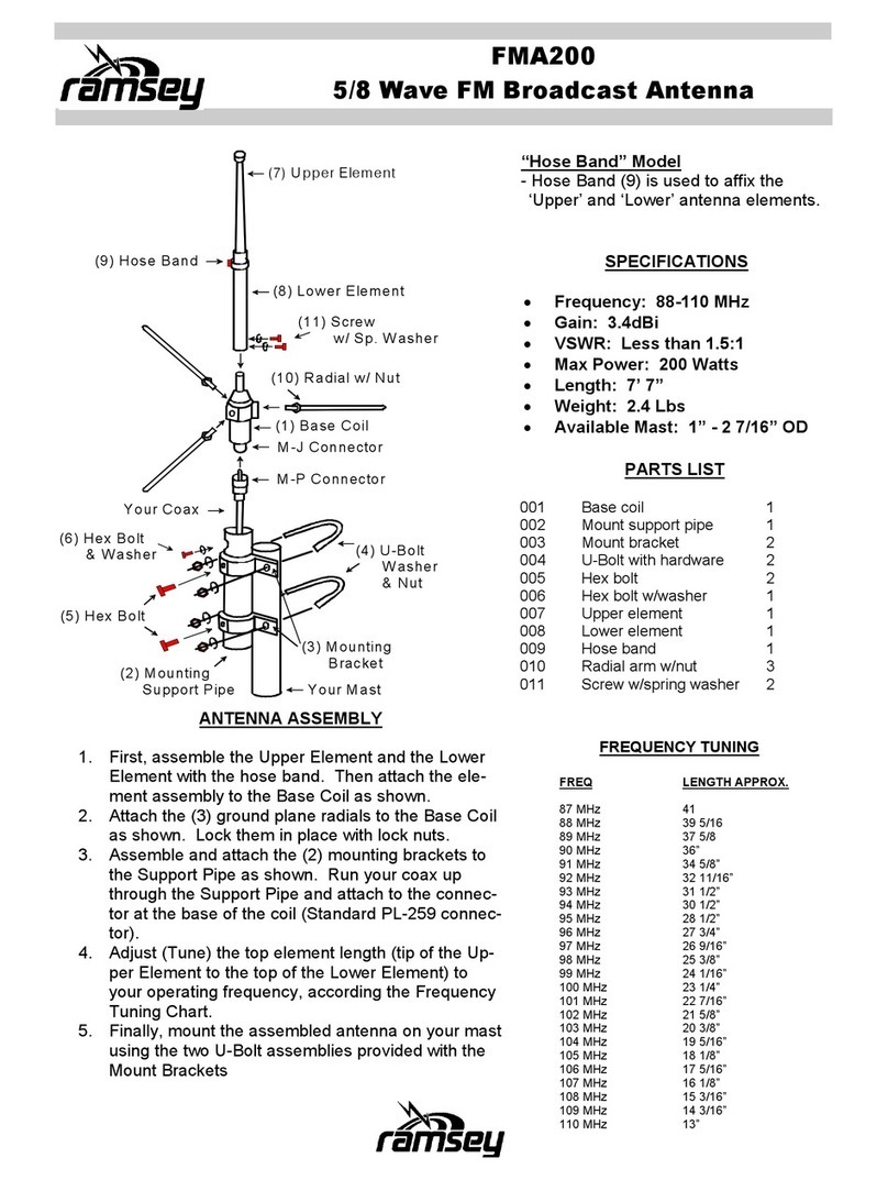
Ramsey Electronics FMA200 User manual

Ramsey Electronics

Ramsey Electronics FMA200 User manual

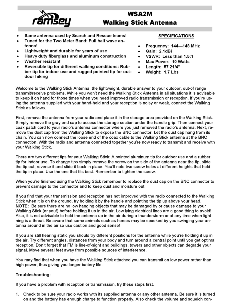
Ramsey Electronics WSA2M User manual

Ramsey Electronics

Ramsey Electronics WSA2M User manual

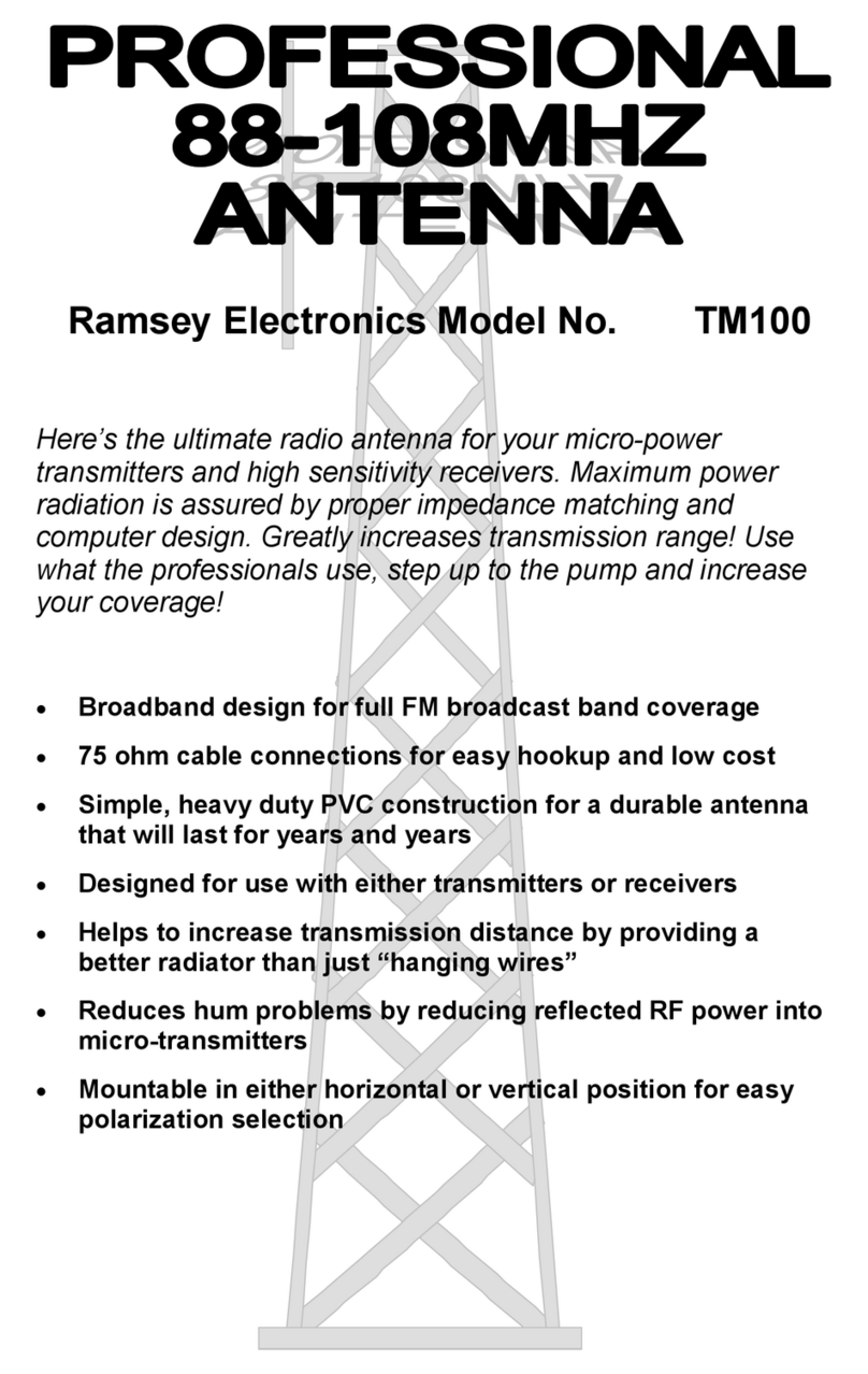
Ramsey Electronics TM100 User manual

Ramsey Electronics

Ramsey Electronics TM100 User manual

Ramsey Electronics DA25 User manual

Ramsey Electronics

Ramsey Electronics DA25 User manual

Ramsey Electronics DA-80 User manual

Ramsey Electronics

Ramsey Electronics DA-80 User manual

Popular Antenna manuals by other brands

DAVIS Windex AV 3160 installation instructions

DAVIS

DAVIS Windex AV 3160 installation instructions

Belden Hirschmann BAT-ANT-N-14G-IP23 Mounting instruction

Belden

Belden Hirschmann BAT-ANT-N-14G-IP23 Mounting instruction

Vtronix YHK Fitting instructions

Vtronix

Vtronix YHK Fitting instructions

KVH Industries TracVision 6 Technical manual

KVH Industries

KVH Industries TracVision 6 Technical manual

Leica Geosystems GS10 user manual

Leica Geosystems

Leica Geosystems GS10 user manual

Sirio Antenne Gain-Master manual

Sirio Antenne

Sirio Antenne Gain-Master manual

Sony VCA-41 Installation/connections

Sony

Sony VCA-41 Installation/connections

ZCG Y100 Series installation guide

ZCG

ZCG Y100 Series installation guide

Advantech Wireless INTREPID120 Assembly instructions

Advantech Wireless

Advantech Wireless INTREPID120 Assembly instructions

Cerio ANT-10AO installation guide

Cerio

Cerio ANT-10AO installation guide

Alfa Network APA-L01 Specifications

Alfa Network

Alfa Network APA-L01 Specifications

Naval PR-422CA Operation manual

Naval

Naval PR-422CA Operation manual

Feig Electronic ID ISC.ANTH200/200 Series manual

Feig Electronic

Feig Electronic ID ISC.ANTH200/200 Series manual

TERK Technologies TV44 owner's manual

TERK Technologies

TERK Technologies TV44 owner's manual

TERK Technologies SIR3 owner's manual

TERK Technologies

TERK Technologies SIR3 owner's manual

Directive Systems & Engineering DSE2324LYRMK quick start guide

Directive Systems & Engineering

Directive Systems & Engineering DSE2324LYRMK quick start guide

HP J8999A instructions

HP

HP J8999A instructions

MobilSat MSP-S Mounting instructions

MobilSat

MobilSat MSP-S Mounting instructions

manuals.online logo
manuals.online logoBrands
  • About & Mission
  • Contact us
  • Privacy Policy
  • Terms and Conditions

Copyright 2025 Manuals.Online. All Rights Reserved.

DAP25 •1
AMPLIFIED
BROADBAND
DISCONE ANTENNA
Ramsey Electronics Model No. DAP25
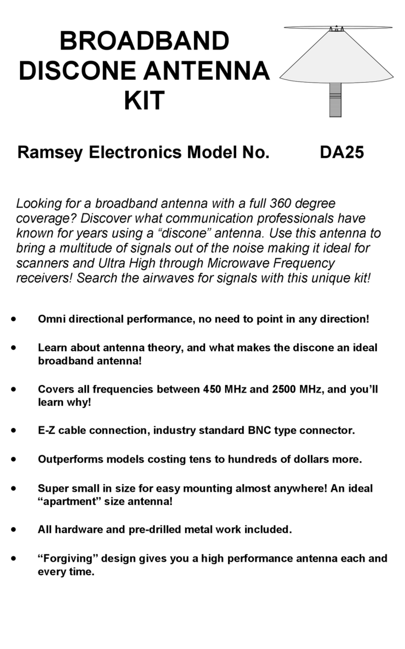
Looking for a broadband antenna with full 360 degree
coverage? Discover what communication professionals have
known for years using a “discone” antenna. Use this antenna to
bring a multitude of signals out of the noise making it ideal for
scanners and Ultra High through Microwave Frequency
receivers! Search the airwaves for signals with this unique kit!
•Omni directional performance; no need to point in any direction!
•Learn about antenna theory, and what makes the discone an ideal
broadband antenna!
•Covers all frequencies between 450 MHz and 2500 MHz, and you’ll
learn why!
•E-Z cable connection, industry standard “F” type connector.
•Out-performs models costing tens to hundreds of dollars more.
•Super small in size for easy mounting almost anywhere! An ideal
“apartment” size antenna!
•All hardware and pre-drilled metal work included.
•“Forgiving” design gives you a high performance antenna each and
every time.
DAP25 •2
RAMSEY TRANSMITTER KITS
• FM100B Professional FM Stereo Transmitter
• FM25B Synthesized Stereo FM Transmitter
• MR6 Model Rocket Tracking Transmitter
• TV6 Television Transmitter
RAMSEY RECEIVER KITS
• FR1 FM Broadcast Receiver
• AR1 Aircraft Band Receiver
• SR2 Short wave Receiver
• SC1 Short wave Converter
RAMSEY HOBBY KITS
• SG7 Personal Speed Radar
• SS70A Speech Scrambler
• BS1 “Bullshooter” Digital Voice Storage Unit
• AVS10 Automatic Sequential Video Switcher
• WCT20 Cable Wizard Cable Tracer
• ECG1 Electrocardiogram Heart Monitor
• LC1 Inductance-Capacitance Meter
RAMSEY AMATEUR RADIO KITS
• DDF1 Doppler Direction Finder
• HR Series HF All Mode Receivers
• QRP Series HF CW Transmitters
• CW7 CW Keyer
• CPO3 Code Practice Oscillator
• QRP Power Amplifiers
RAMSEY MINI-KITS
Many other kits are available for hobby, school, Scouts and just plain FUN. New
kits are always under development. Write or call for our free Ramsey catalog.
DAP25 KIT INSTRUCTION MANUAL
Ramsey Electronics publication No. MDAP25 Rev 1.4
First printing: November 2001
COPYRIGHT 2001 by Ramsey Electronics, Inc. 590 Fishers Station Drive, Victor, New York
14564. All rights reserved. No portion of this publication may be copied or duplicated without the
written permission of Ramsey Electronics, Inc. Printed in the United States of America.
DAP25 •3
BROADBAND DISCONE
ANTENNA KIT
DAP25
Ramsey Publication No. MDAP25
Price $5.00
TABLE OF CONTENTS
Introduction................................. 4
Circuit description .......................8
Parts list......................................9
Schematic and Parts diagram.....10
Assembly instructions .................11
Using your DAP25 ......................17
Troubleshooting guide ................17
Warranty.....................................19
KIT ASSEMBLY
AND INSTRUCTION MANUAL FOR
RAMSEY ELECTRONICS, INC.
590 Fishers Station Drive
Victor, New York 14564
Phone (585) 924-4560
Fax (585) 924-4555
www.ramseykits.com
DAP25 •4
INTRODUCTION
In today’s ever growing “wireless” society, it almost seems a bit ironic that
antennas have become less and less the topic of interest in hobbyist circles.
The recent advances in wireless technology have shrunk antennas to ever
smaller an unobtrusive sizes. An example of this is the cable television industry.
They have removed the larger “traditional” antenna arrays that were once
commonplace for TV reception and replaced them with a single wire or two
entering the household. Advances in the semiconductor industry have provided
engineers with the tools to pull the smallest signals from the airwaves with
better noise performance than could have been dreamed of when the
technology of radio reception was envisioned. Advances in satellite technology
have reduced the size of a reception “dish” from over 12 feet in diameter to a 1
foot round platform!
Antenna design certainly has not made the “quantum leap” that was brought on
with the advances in the semiconductor industry, but it is just as important as it
was in those early days of radio. The original aerials, or reception antennas,
had to provide enough signal to overcome the ever present noise and allow the
early receivers to detect and demodulate signals. These early antennas were
quite large (we’ll talk a little more about this later) due to the lower frequencies
being transmitted. Again, more recent improvements have allowed us to use
higher frequencies with significantly smaller antennas.
With less and less demand for consumer antennas, the market price of these
commodities has increased. As many of us have discovered, even the lowest
cost antennas run in excess of one hundred dollars! While they are necessary if
we intend to use the antenna commercially or for television reception, it simply
is too much for a hobbyist to invest for use with a monitoring receiver. Enter the
Ramsey line of discone antennas, allowing us to “tinker” with the airwaves at an
affordable price.
Ramsey Antennas 101:
Before we break open our discone kit, lets talk about what makes an antenna
tick, and some of the terms used to define antenna performance.
How Fast are Radio Waves?
If one were to “whip” the end of a taught length of rope, you could observe the
wave created traveling down the rope to it’s end. Going back to our physics
class, recall that the speed of any object is the distance it travels divided by the
time it takes to get there, or Velocity = Distance / Time. The time a wave takes
to travel is dependant on the type of wave and the transmission medium. The
wave in our rope example can take seconds to traverse down the length of the
medium. Sound waves travel about 1100 feet every second; if we called out
DAP25 •5
before we snapped the rope, the sound waves would arrive much quicker than
the “rope wave” would. In the case of radio waves, the rate at which the waves
travel is much faster, reaching the speed of light (186,000 miles / second, or
about 3x10⁸meters / second) in a vacuum. Radio waves do travel slightly
slower in air however. In a wire transmission line, they travel even slowly!
Frequency and Wavelength
Since all antennas collect electromagnetic waves, lets take a moment to think
about the wave motion of the radio wave itself. Try to picture a repeating
sinusoidal waveform moving down a line (oscillating). A wave that repeats itself
has a certain period (amount of time) that it takes to complete a full cycle.
Since this cycle is regular, we say that the wave has a frequency of repetition.
This frequency in fact is the reciprocal of the time it takes for the wave to
complete one full cycle, mathematically speaking f = 1 / T. By the same token
the time and frequency are related by the expression T = 1 / f.
The distance in free space that the wave takes to repeat itself is said to be the
wavelength and can be calculated using the same velocity equation. By
rearranging the velocity equation algebraically, we can say that the
Distance = Velocity x Time. Since we will approximate the velocity to be the
speed of light (“c”), once the Time is determined we can solve for the distance
traveled which is the wavelength; usually denoted as the Greek letter lambda
(“λ”) reducing our equation to λ= v x T. In English, the wavelength is equal to
the velocity multiplied by the period of the waveform. Pretty neat, huh!
One Wavelength
One Cycle
Some Amount of Time
Electromagnetic Wave
DAP25 •6
What Are We Driving At?
Time to pull some of that theory together and get some answers:
Since: λ= v x T
And T = 1 / f
We can substitute and get:
λ= v / f
Since the velocity equals “c” we wind up with:
λ= c / f
The wavelength of the radio wave equals the speed of light divided by the
frequency.
Lets plug some numbers into our equation and work out a few wavelengths. We
should notice some other properties of electromagnetic waves.
If f = 450 MHz (the wave cycles 450 million times in a second) then λ = 3x 10⁸/
450 x 106or .666 meters for a full wavelength.
If f = 2500 MHz (the wave cycles 2500 million times in a second) then λ = 3x
108/ 2500 x 106 or .120 meters for a full wavelength.
It’s important to note that as the frequency of a wave increases, its wavelength
decreases. Keeping in mind the introduction section where we talked about
antenna size, lets consider the “old” days of radio. The common use of low
frequencies meant much longer wavelengths and significantly larger antennas
for reception. Today's modern electronic devices tend to operate at much
higher frequencies and thereby require smaller antennas to operate properly.
Determining the Resonant Frequency of the Antenna
Let’s explore another factor in antenna as well as radio design, the resonant
frequency of the circuit. Recalling that we would like our discone antenna to
work over a large range of frequencies, we need the antenna system to be
optimized for the full desired range. Resonance in an antenna circuit occurs
when the antenna length exactly matches the wavelength of the desired
frequency. To make an antenna resonant over a range of frequencies, it needs
to look like a multitude of lengths.
Looking at the desired waveform, the shortest length of wire that will resonate
at a given frequency is one which is just long enough to permit an electric
charge to travel from one end to the other and then back again in the time of
DAP25 •7
one radio frequency (or RF) cycle. Since the charge traverses the wire twice,
the length of wire needed to permit the charge to travel the total distance in
one cycle is λ / 2, or one half the wavelength. Therefore, the shortest resonant
wire length will be one half wavelength long.
Let’s consider a “half wavelength” example to help it make sense. Picture a
trough with barriers at each end. If a rubber ball is rolled along the trough from
one end to the other it will hit the end and bounce back. When it bounces
back, it will hit the near barrier and bounce again. This will continue until the
ball runs out of energy and stops. If however, whenever the ball returns to the
near barrier it is given a push just as it starts away, its back and forth motion
can be kept up indefinitely as long as the impulses are timed properly. In other
words, the rate or frequency of the impulses must be adjusted to the length of
travel and the rate of travel. If the timing of the impulses (the push) and the
speed of the ball are fixed, the length of the trough must be adjusted to “fit”. In
the case of the antenna, the speed is constant. This leaves the alternatives of
adjusting the frequency or the length of wire to match a given frequency.
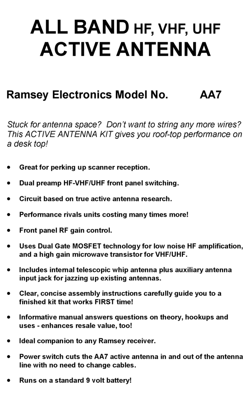
Antenna Gain
Another performance specification common with
antennas is their gain, usually given in dBi units. To
understand this concept, let’s explore the “i” in the dBi
unit as an isotropic source. Imagine a point in space as
a source of a radiating signal. The signal would then
expand spherically from the point source. If we then
move a given distance from the point source, the power
would be distributed uniformly in all directions. The
power density is uniform about an isotropic source and
thus is related to the surface area of a sphere (area =
4x πx radius 2). Although this is not practically
possible, it is the basis for an antenna gain specification. The gain of an
antenna is usually referenced in comparison to this type of source in a decibel
unit with a logarithmic relationship. Without getting hung up too much on
logarithmic theory, suffice it to say that an increase of 3 dB is equal to twice
the power being present . An increase of 10 dB is equivalent to a gain factor of
10. For example, a 1 Watt signal with a gain of 3 dB equals two Watts, while
the same power with 10 dB gain is 10 Watts.
Although we are using our discone as a receiving antenna, the rules of
antenna gain are reciprocal so we can count on at least a 14 dBi improvement
in the signal power over the entire frequency range.
DAP25 •8
What About Impedance Matching and VSWR ?
Another consideration with electromagnetic wave antennas is the “match”
presented to either the receiver or transmitter. In our discussion of wavelength
and resonant frequencies it became apparent that the length of the antenna is
critical to match that of the desired frequency. A small error in length can
detune an antenna significantly and inhibit the antennas performance.
For many communications systems, 50 or 75 Ohms are the desired “magical”
impedance values desired for the antenna systems. The proper impedance
allows for maximum power to transfer to or from the antenna system with a
minimum of loss. Even with the high frequencies being used we want the
antenna to appear as a proper load. In this way the antenna presents a good
match to the receiver. Luckily for us, the discone antenna exhibits exceptional
performance in the impedance matching department.
The Voltage Standing Wave Ratio (VSWR) of an antenna system is another
measure of this impedance match. At RF frequencies, if the load at the end of
the transmission line is not the desired impedance, the signal will actually
reflect back down the line and precipitate a high VSWR. Typical usable VSWR
ratios are in the “3.0 : 1.0” range for commercial available communications
equipment, while the robust discone design actually outperforms these at
many frequencies with a typical ratio of “1.5 : 1.0” or better. A “1.0 : 1.0” ratio
indicates the best match possible resulting in no wasted signal reflection.
DISCONE DESCRIPTION
Getting back to the kit at hand, let us apply some of the theory we just
discussed. Notice that the discone antenna is predominately two sections, the
upper “disk” and lower “cone” section.
To allow for the large frequency range of the antenna, notice how the lower
cone section of the antenna slopes away from the top disk section. This
design allows for a smooth transition between the multiple wavelengths that
we hope to receive without any discontinuities in between. This is an ideal
configuration for an omni-directional antenna response pattern.
The coaxial cable mounts directly to the provided circuit board plate, which in
turn will be connected to both the conic section as well as the top disk of the
antenna. The cable has been supplied with a crimped BNC type connector at
one end for ease of connection to your receiver.
The discone dimensions have been calculated such that the usable
performance range is between 450 MHz to 2500 MHz with a typical VSWR of
“2.0 : 1.0” or less.
The amplified discone antenna takes advantage of a low noise MMIC amplifier
DAP25 •9
to provide additional gain for the antenna. The 9 VDC power to run the
amplifier is “piggy-backed” up the RF cable and is decoupled at the antenna
circuit board. There is also an additional protection diode on the amplifier input
to prevent any damage to the sensitive IC.
Ramsey offers two models of this particular antenna, one with no active
components and the other with a low noise preamplifier to further boost the
antenna gain.
The DAP25 kit which your are about to assemble is the preamplified version.
The advantages to this particular model are that in addition to the gain and
performance of a standard discone antenna, the DAP25 offers an additional
low noise amplifier to provide higher gain for reception of weak signals.
However, if your particular application is for transmission of signals, this is not
the kit for you. The low noise amplifier could be damaged by injecting RF
power into the antenna. We recommend the non-preamplified version of this
kit, the DA25, for transmitting applications. The good news is if you have not
begun assembly yet, you may return your kit for full credit towards the non-
amplified version within 10 business days from original purchase.
PARTS SUPPLIED WITH YOUR DAP25 KIT
1 3 Qt. funnel “cone”
1 7 inch pie-plate (CAUTION, EDGES MAY BE SHARP!)
3 #6 – 32 x 1/4” screws (Nylon)
3 #6 – 32 M-F stand-offs (Nylon)
3 #6 – 32 nuts (Nylon)
1 DCA1 circuit board
1 PVC coupling
1 3” buss wire
1 3’ length type “F” to jumper cable
1 Feed thru power inserter with wall plug transformer
SURFACE MOUNT COMPONENTS: Note there are extra chip capacitors and
resistors included (They’re real small aren’t they!).
3 220 ohm surface mount resistors (marked 221) [R1-3]
2 .001 uF surface mount capacitors (Gray smt package or marked A3)
[C1,2]
1 33 nH surface mount inductor (White smt package or marked R33)
[L1]
1 BAV99 dual diode (three tabs marked 7X ) [D1]
1 MMIC amplifier (four solder tabs marked 5) [U1]
DAP25 •10
DAP25 PREAMPLIFIER SCHEMATIC DIAGRAM
DAP25 PREAMPLIFIER PARTS PLACEMENT DIAGRAM