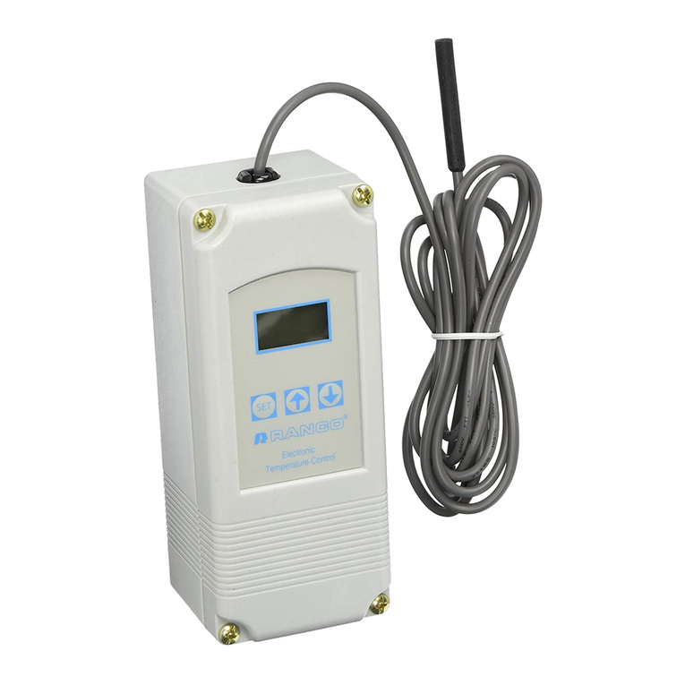
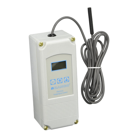
Ranco ETC-211000-000 User manual

Form
No.
7515004-001
Rev.
B
ETC TWO STAGE ELECTRONIC TEMPERATURE CONTROL
PRODUCT DESCRIPTION RELAY ELECTRICAL RATINGS
120v 2081240V
The RancoETCisamicroprocessor-basedfamily NO Contact
of electronic temperature controls, designed to Full-loadamps 9.8
A
4.9 A
provideonloffcontrolforcommercialheating,cool- Lockedrotoramps 58.8 A 29.4
A
ing,airconditioningandrefrigeration.TheETCis Resistiveamps 9.8 A 4.9
A
equipped with a liquidcrystal display (LCD) that Horsepower 112 hp 112 hp
providesa constant readout of the sensed tem-
perature,andatouchkeypadthatallowsthe user NC Contact
to easilyand accuratelyselectthe set pointtem- Full-loadamps 5.8 A 2.9 A
perature,differentialandheating/coolingmodeof Lockedrotor amps 34.8
A
17.4 A
the operation. Modelsare availablethatoperate Resistiveamps 5.8
A
2.9 A
on either linevoltage Horsepower 114 hp 114 hp
(12012081240 VAC) or lowvoltage(24VAC). ilot Duty:
125
VA at 12012081240VAC
C
-
APPLICATIONS
With itswidetemperature
setpoint rangeandselectable
heatingor coolingmodes,the
FTCcanbe usedfor awide variety of
ControlAmbient Temperature
Operating -20°F to 140T(%!VRht&~°C)
Storage -40°F to176°F (-40°C to80°C)
Ambient Humidity 0 to 95%, RH, Non-condensing
0to 10VOutput Impedance 1
K
-
Enclosure NEMA 1. Plastic
I-
-
-
applications includingmultiple Agency Approvals ULListed, FileE94419,Guide XAPX
compressorcontrol,two stage heating, CSA Certified, FileLR68340, Class 4813 02
ventilationcontrol, automatic chaqw
ETC ORDERNG INFORMAT
-
--
space and returnairtemperature control,water cooled condensers
andcontrolwith alarm funtion.
FEATURES
r
Widesetpointtemperaturerange(-30°F to 220°F) and
differentialadjustment (1°F to 30°F).
r
Simple keypad programmingof setpointtemperature,
differentialandcoolingheatingmodes.
r
Two individuallyprogrammablestages for heating
andlorcooling.
r
LCD readoutof sensortemperature, controlsettings,
relaystatus andonboarddiagnostics.
Remotetemperature sensingup to 400feet.
r
Two SPDToutput relays.
r
User-selectable FahrenheitICelsiusscales.
r
Lockoutswitchto prevent tampering by unauthorized
personnel.
r
Choice of linevoltage and low voltagemodels available.
r
Optional0 to 10volt analogoutput availablefor remote
temperature indication.
SPECIFICATIONS
InputVoltage 120or 2081240 VAC (24VAC optional), 50160
Hz
Temperature Range -30°F to220°F
Input No. of 0-10V
Code Number Voltage Stages Output
ETC-211000-000 1201240 2 NO
ETC-211100-000 1201240 2 Yes
ETC-212000-000 24 2 NO
ETC-212100-000 24
2
Yes
OPERATION
Liquid Crystal Display(LCD)
The LCDdisplay providesa constantreadout of the sensor temperature
and indicatesif either of the two output relays isenergized. When the
S1
annunciator isconstantlyilluminatedduringoperation, the Stage 1 relay is
energized. Likewise,when the S2 annunciatorisconstantlyilluminated
duringoperation, the Stage2 relayisenergized. The display isalso used
inconjunctionwith the keypadto allowthe userto adjustthe setpoint
temperatures, differentialsand heatinglcoolingmodesfor each stage.
Control Setup
The temperaturesetpointrefersto the temperatureat which the normally
open
(NO)
contactsof the output relaywill open. Determinethe loadsto
be controlledandthe operatingmodes requiredfor each stage, coolingor
heating.
@Whenthe cooling mode ischosen, the differential isabove the setpoint.
The relaywill de-energizeasthe temperaturefalls tothe setpoint.
-
DifferentialRange 1OF to30°F
SPDT *When the heatingmode ischosen, the differential isbelow the setpoint.
Switch Action relaywill de-energizeas the temperature risesto the setpoint.
Sensor Thermistor, 1.94in. long
x
0.25 in. dia
8
ft.
cable The ETCtwo stage control can be set upfor two stages of heating,two stages
Power Consumption 12012081240VAC
:
100milliamps of coolingor one stage cooling plus one stage heating. Referto Figures 1,2
24VAC
:
2-6VAC and 3for avisual representationsof differentcontrolsetups.

ON
=
ENERGIZED
OFF
=
DE-ENERGIZED
STAGE
1
ON
OFF
STAGE
2
ON
(-1
+
Figure1: Two StageHeatingExample
ON
=
ENERGIZED
OFF
=
DE-ENERGIZED
STAGE
2
1
SETPOINT
.
.-..
...
..
.
.
.
...
..
.
.
.
ON
STAGE
2
OFF
ON
STAGE
1
.
.
......
QF.
Figure
2:
Two StageCooling Example
ON =ENERGIZED
OFF
=
DE-ENERGIZED
STAGE
1
f
""y;u
SETPOINT
..
,..
..
.-
..
...
STAGE
2
HEATING
ON
Programming
Stsps
and
Moplay
The ETC two stage can beprogrammedinseven simple steps usingthe LCD
display andthethree keysonthe face of the control.
Step
1
-
To start programming, pressthe SET key once toaccessthe
FahrenheitlCelsiusmode. The display will showthecurrent
status, either
F
for degrees Fahrenheitor Cfor degreesCelsius.
Then presseither the up
4
or down
+
arrow keyto toggle
betweenthe
F
or C designation.
Stage
1
Step
2-
Pressthe SET keyagainto accessthe stage
1
setpoint. The
LCDwill displaythe currentsetpointandthe S1 annunciatorwill
beblinkingon andoff to indicatethat the control isinthe setpoint
mode. Then presseitherthe up
4
key to increaseor the down
+
keyto decreasethesetpointto the desiredtemperature.
Step
3-
Pressthe SET key againto access the stage
1
differential. The LCDwill
displaythe current differentialand the
DIF
1
annunciator will be
blinkingon andoff to indicatethatthe control isinthe differential
mode. Then presseitherthe up
4
keyto increaseor the down
+
keyto decrease thedifferentialto the desiredsetting.
Step
4-
Pressthe SET keyagainto access thestage
1
coolingor heating
mode. The LCDwill displaythe currentmode, either C1 for
.
coolingor HIfor heating. Then press eitherthe up
4
ordown
+
keyto toggle betweenthe C1or HIdesignation.
7
Step
5-
Pressthe SET key again to accessthe stage
2
setpoint. The LCD
will display the current setpointand theS2 annunciatorwill be
blinkingon and off to indicatethat the controlisinthesetpoint
mode. Then presseitherthe up
4
key to increaseor the down
+
key to decrease the s&etpointtothe desiredtemperature.
&ep
6-
Pressthe SET key againto accessthe stage
2
differential.The
LCDwill displaythecurrentdifferential and the
DIF
2
annunciato
will be blinkingon and off to indicatethat the control isinthe dif-
ferential mode. Then presseitherthe up
4
key to increaseor the
down
+
keytodecrease the differentialto the desiredsetting.
Step
7-
Pressthe SET keyagain to access the stage
2
coolingor heating
mode. The LCDwill display the current mode, either C2 for cool-
ingor
H2
for heating. Then presseitherthe up
t
or down
+
key
totoggle betweenthe C2 or H2designation. Pressthe SET key
once moreand programmingis complete.
Refer to Page
3
for an illustratedguide to programmingthe ETC.
NOTE: The ETCwill automaticallyend programmingif nokeysare
depressed for a periodof thirty seconds. Any settingsthat have
beeninput to the control will beacceptedat that point.
Allcontrolsettingsare retainedinnon-volatilememoryif powerto ETC
is interruptedfor any reason. Re-programmingis not necessary
after poweroutagesor disconnectsunlessdifferentcontrolsettings
are required.
Figure
3:
OneStageCoolingand OneStageHeatingExample

S1
(blinking)
DIF
Fahrenheii
or CelsiusScale
i
-
Stage
1
MpantTemperature
5
I;.YROUBLESHOOTING
.
.
ERROR MESSAGES
'--
'-a-
Display
Display
ksages
El-
Appears when eitherthe up
4
or down+ key ispressedwhen
not inthe programming mode.
To correct:
If the
El
messageappears even when no keysare
beingpressed, replacethe control.
E2-
Appears if the control settingsare not properly stored in memory.
1
(blinking) Stage
I
DierentialTempemture
jnl
To correct:
Check all settingsand correct if necessary.
EP-
Appears when the probeis open, shortedor sensinga
Stage
1
Coolingor HeatingMode
S2
(blinking) Stage
2
Setpolnt
Temperature
-
<
#
/
DIF
2
(blinking)
Stage
2
DierentialTemperature
Stage
2
Coolingor
Heating
Mode
temperature that isout of range.
To correct:
Check to see if thesensed temperatureis out of range.
If not, check for probedamage by comparing itto a knownambient
temperaturebetween
-30°F
and
220°F.
Replacethe probeif necessary.
EE-
Appears if the EEPROMdata has been corrupted.
To correct:
This condition cannot be field repaired. Replacethe control.
CL-
Appears if calibrationmode has been entered.
To correct:
Removepowerto the controlfor at leastfive seconds.
Reapplypower.
If
the
CL
messagestill appears, replace
the control.
INSTALLATION INSTRUCTIONS
IMPORTANT
.
-
--
1.
AllETCseriescontrolsaredesignedasoperatingcontrolsonly. Ifan
keypadisdisabledandnochangestothesettingscan
be
made. When operatingcontrolfailurecould result in personalinjuryor loss of
placedinthe
UNLOCK
position,the keypadwill functionnormally. property, aseparatesafety controlandloralarmshouldbeinstalled.
Toaccessthelockoutswitch,disconnectthepowersupplyandopen
thecontrol. The switchis locatedon the insidecover about
2
inches
abovethe bottom. (see Figure
4).
To disablethe keypad, slide the
switchto the left
LOCK
position. To enable the keypad, slide the
switchto the right
UNLOCK
position. All
ETC
controlsare shipped
withthis switchinthe
UNLOCK
position.
LOCK
UNLOCK
1
Ill
I
FIELAY
RATIWGS
RONC.
MSPUY
CODES
VAC
I#)
ZWMO
F
FIHREWHUT
2.
The schematic drawingsand other informationincludedin
these installationinstructionsare for the purpose of illustration
.
and generalreferenceonly.
d.e
3.
These instructionsdo not expand, reduce, modify or alter the Ranco
Termsinanyway; andnowarrantyorremedyinfavorof thecustomer
or any other personarisesout of these instructions.
4.
Ranco ETCcontrols have beenapprovedby Underwriters'
Laboratoriesas
UL
Listed; however,approval does not extendto
theiruseforanyotherpurpose. Rancoassumesno responsibilityfor
any unconventionalapplicationof itscontrolunlesssuchapplication
has beenapprovedinwriting by Ranco.
5.
Itistheresponsibilityof theinstallerandtheusertoassurethat hisor
itsapplicationanduseof all Rancoproductsare incompliancewith
allfederal, stateand local requirements, including, without any
limitation,allrequirementsimposedundertheNationalElectricCode
andany applicable buildingcodes.
I
.P
TEMP
*
EP
PROBE
PAWRO
OUT
OPRANQE
REG
EQUIP
SzN8
EE
EEPROM
FAILURE
USE
COPPER
Ei
IMPROPER
KEY
I
Figure
4:
LockoutSwitch

CAUTION
To preventpossibleelectricalshock or equipment damage,
disconnect electricalpowertothe unit before andduring installa-
tion.
DO
NOT
restore electricalpower to unituntilthe controlis
properly installedand the cover isassembled.
DO
MOT
locatethc
control inan explosive atmosphereas asafety hazardcan result
{
due to possiblespark generationinthe control. Controlsare
=
tobe locatedin areas of significant moisture, dirtor dust, or ina
corrosiveexplosive atmosphere. Use of control in such environ-
ments may result ininjury or damage tothe personsor property
(or both) andare likelyto shortenthe control life;
Ranco,agsumes
no
responsibilityfor any+uch
uys.
,,
,
-.
-
>-
-
CONTROL MOUNTING
Mountthe ETCtoawall oranyflatsurfaceusingacombinationof anytwo
or more of theslottedholeslocatedon the backof thecontrolcase. The
control'scomponentsarenotpositionsensitive,butshouldbemountedso
thatthey canbeeasilywiredandadjusted. Avoid excessiveconditionsof
moisture, dirt, dust andcorrosiveatmosphere.
The ETChasprovisionsfor
112
inchconduitconnections. Theconduithub
should be secured to the conduit before securing the hub to the plastic
housingof thecontrol. When usingtheconduitentryintherearofthecase,
a standard plug should be inserted into the conduit hole in the bottom.
Caution should be exercised not to damage the control circuit board
or
wiringwhen installing
a
conduitconnector.
KNOCK-OUT
FOR
0.50
DIA
CONDUIT
TRADE
SIZE
BOTTOM
VlEW
n
REAR
VIEW
Figure
5:
Dimensions(Inches)

CONTROL
WlRl
General
&.
--,
All wiring should conformtothe NationalElectricCode and local
regulations.
The total electricalloadmust not exceedthe maximum
ratingof the control (see Specifications).
Use copper conductorsonly.
Electricalleads should not betaut; allow slack for
?
24
VAC
CLASS
2
temperature changeand vibration.
lnputand Output Wiring
Fortypical wiring diagrams, referto Figures
6
and
7.
Allconnectionsare madeto the power (lower)circuit board. When using
the24
VAC
powered models,the 24
VAC
input linesmust enter through the
sidewall of the case. Referto Figure
5
for location of the entry hole.
-
Analog Output
ETC
modelsare availablewith an optional
0
to
10
volt analog output.
This signalisa linearrepresentationof the sensor temperaturewith
0 volts
=
-30°F and
10
volts
=
220°F. Seefigure
8
for wiring information
and Figure
5
for locationof the entry hole. The referencefor this output
isdesignatedby the
tU
symbolon the wiring diagram. The output signal
is designatedbythe
"tu
symbol.
-7-r
-
SensorWiring
&
--
-
The temperature sensor leadsare solderedto the circuitboardso no
I
-1
-
LINE
VOLTAGE
-
Figure
7:
Typical W~nngDiagramfor
24
VAC PowerInputand
LineVoltageSwitching.
additionalconnectionsare necessary. However,splicing is required
when extendingthe sensor cablelengthbeyondthe standard
8
foot length
,
duppli blecan be extended up to 400feet.
h-
-
A dam
the sensor leadsfrom the circuit board. Thesensoris not polaritysensitive.
Figure
120
VAC
Figure
6:
Typical LineVoltage Wiring Diagram.
0
v
OUTPUT
8:
0-10
V
Analog Output LocatedonPower (Lower) Circuit Board.
FIELD
REPAIRS
Fieldcalibratingorrepairstothe ETCcontrolmust not
be
attempted.
Sensorsandreplacementcontrolsareavailablethrough Ranco
wholesalers

SENSOR MOUNTING
For spacesensing, mount the sensorwhere itwill be unaffectedby
heatlcooldischargeor radiatedheat sources. Spot sensing requires
the sensorto be ingood contactwiththe surface beingsensed. The
sensor can be insertedina bulbwell for immersion sensing.
EXTENDING SENSOR
CAUTION: Sensorwiring splices may be made external from the
control. DO NOTattempt tyo unsolder the sensor at the controlcircuit
board!
CAUTION: Disconnectpowerto controlbeforewiringto avoid possible
electricalshock or damage to the controller.
Additional cable can be splicedto thesensor cableto increasethe
lengthbeyondthe standard
8
feet. Itcan be extended up to
400
feet.
The cable should be at least
22
AWG or largerto keep additional
resistanceto
a
minimum.
All splicesandwire lengthsaddedto the sensorcable should
t~
accordingto acceptable wiring practicesand shouldconformto the
NationalElectricalCode and localregulations. Usecopper conductors
only. Shielded cable isnot required.
I
CheckoutProcedure
1.
Beforeapplyingpower, make sure installationandwiring
connections are correct.
2.
Apply powerto the controlandobserveone or morecycles of
k4
,.,
operation.
3.
If performanceindicatesa problem,check sensor resistanceto
determine if sensoror controlisat fault.
4.
To checksensor resistance,disconnectsensor and measurethe
resistanceacrossthe leadswhile measuringtemperature at the
sensor.
SENSOR
3
NSOR
I
(4)
Sensorswired in serieslparallelfor temperatureaveraging.
I
SENSOR SENSOR
H
ETC
CONTROL
Figure
9
Replacement Sensor
-
Order
Part
No.
1309007-044
SPECIFICATIONS
The
1309007-044
sensorisa negativetemperaturecoefficient (NTC)
thermistorsensor. The sensor resistancedecreases with temperature
increase. Itis
.25
x
1.94
longwith
8
feet
#22
AWG cable. The
termistorhasa referenceresistanceof
30,000
ohmsat
77°F (25°C).
Fi ure
10:
Resistance
vs
Temperature
of
130!007-044.
Sensor
including
8
footcable.
The schematic drawings and other informationincludedinthese
instructionsare for the purposeof illustrationandgeneralreference
only. Rancoassumes no responsiblityfor any unconventional
applicationof this control, unlesssuch applicationhasbeen approved
in writing by Ranco.
81 15
U.S. Rt.
42
N. Plain City, Oh
43064
Deg.C.
-40
-30
-20
-1
0
0
10
20
25
30
40
50
60
70
80
90
100
110
An lnvensys~ompiiy
Deg.F.
-40
-22
-4
14
32
50
68
77
86
1
04
122
140
158
1
76
1
94
21 2
230
RES.
Nom.
1,010,000
531,000
291,200
166,000
97,960
59,700
37,470
30,000
24,170
15,980
10,810
7,464
5,200
3,774
2,753
2,036
1,531
This manual suits for next models
3
Table of contents
Other Ranco Temperature Controllers manuals
Popular Temperature Controllers manuals by other brands

Ropex
Ropex Resistron RES-5011 operating instructions

BASIC DC
BASIC DC Solareg II operating manual

Eden
Eden RCE10E Installation and use guide

Elotech
Elotech R 1120 Description and Operation Manual

S+S Regeltechnik
S+S Regeltechnik Thermasreg RTR-S Series Operating Instructions, Mounting & Installation

Ropex
Ropex RESISTRON RES-440 Replacement instructions