manuals.online logo
Brands
  1. Home
  2. •
  3. Brands
  4. •
  5. Omron
  6. •
  7. Temperature Controllers
  8. •
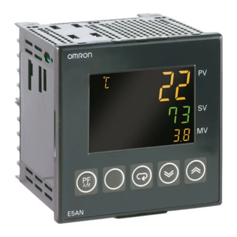
  9. Omron E5*N Series Installation guide

Omron E5*N Series Installation guide

Other manuals for E5*N Series

1

This manual suits for next models

4

Other Omron Temperature Controllers manuals
Omron E5GN User manual

Omron

Omron E5GN User manual

Omron E5 C Series User manual

Omron

Omron E5 C Series User manual

Omron E5AJ-A2HB User manual

Omron

Omron E5AJ-A2HB User manual

Omron E5CC User manual

Omron

Omron E5CC User manual

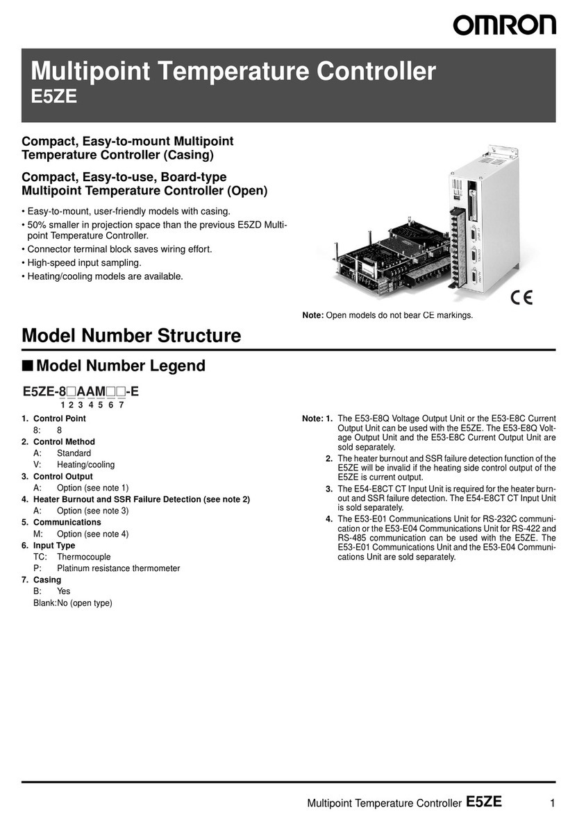
Omron E5ZE User manual

Omron

Omron E5ZE User manual

Omron C200H-TV Series User manual

Omron

Omron C200H-TV Series User manual

Omron EJ1N-TC4 User manual

Omron

Omron EJ1N-TC4 User manual

Omron E5AN-H User manual

Omron

Omron E5AN-H User manual

Omron E5CD-B-800 Series User manual

Omron

Omron E5CD-B-800 Series User manual

Omron E5CC-800 User manual

Omron

Omron E5CC-800 User manual
Omron E5CWL Instruction manual

Omron

Omron E5CWL Instruction manual

Omron E5ZN-DRT User manual

Omron

Omron E5ZN-DRT User manual

Omron E5DC User manual

Omron

Omron E5DC User manual

Omron E5CSZ User manual

Omron

Omron E5CSZ User manual

Omron E5CN Owner's manual

Omron

Omron E5CN Owner's manual

Omron E5_N-H Series User manual

Omron

Omron E5_N-H Series User manual

Omron E5AN User manual

Omron

Omron E5AN User manual

Omron E5CSV - User manual

Omron

Omron E5CSV - User manual

Omron E5CC User manual

Omron

Omron E5CC User manual

Omron E5CN User manual

Omron

Omron E5CN User manual

Omron E5EC-T User manual

Omron

Omron E5EC-T User manual

Omron E5CS-U User manual

Omron

Omron E5CS-U User manual
Omron E5CN User manual

Omron

Omron E5CN User manual
Omron E5CN User manual

Omron

Omron E5CN User manual

Popular Temperature Controllers manuals by other brands

Brookfield TC Series Operator's manual

Brookfield

Brookfield TC Series Operator's manual

Nibe HPAC 45 Installer manual

Nibe

Nibe HPAC 45 Installer manual

Auber TD100 instruction manual

Auber

Auber TD100 instruction manual

IntelliSense INTELLITEMP T-1000 installation instructions

IntelliSense

IntelliSense INTELLITEMP T-1000 installation instructions

Swegon LUNAd MB Instructions for use

Swegon

Swegon LUNAd MB Instructions for use

Lucky Reptile Thermo Control II Operation instructions

Lucky Reptile

Lucky Reptile Thermo Control II Operation instructions

SMC Networks Thermo-con INR-244-639 Operation manual

SMC Networks

SMC Networks Thermo-con INR-244-639 Operation manual

SENSORMETRIX Argon 100 manual

SENSORMETRIX

SENSORMETRIX Argon 100 manual

Fuji Electric PXE4 instruction manual

Fuji Electric

Fuji Electric PXE4 instruction manual

Yuyao gongyi XMT-808 series Operation manual

Yuyao gongyi

Yuyao gongyi XMT-808 series Operation manual

eltherm Ex-TC It Series operating instructions

eltherm

eltherm Ex-TC It Series operating instructions

Selec TC544C user guide

Selec

Selec TC544C user guide

P.W. KEY rt-208gt operating manual

P.W. KEY

P.W. KEY rt-208gt operating manual

BH Thermal BriskONE owner's manual

BH Thermal

BH Thermal BriskONE owner's manual

West Control Solutions KS 45 Operation Notes

West Control Solutions

West Control Solutions KS 45 Operation Notes

Opt Lasers TEC-8A-24V-PID-HC operating manual

Opt Lasers

Opt Lasers TEC-8A-24V-PID-HC operating manual

Vaillant VR 92/3 Operating and installation instructions

Vaillant

Vaillant VR 92/3 Operating and installation instructions

Vector TCY-FT-U manual

Vector

Vector TCY-FT-U manual

manuals.online logo
manuals.online logoBrands
  • About & Mission
  • Contact us
  • Privacy Policy
  • Terms and Conditions

Copyright 2025 Manuals.Online. All Rights Reserved.

CONTENTS
1. Setting the Sensor Type
2. Using ON/OFF Control
3. Using PID Control
4. Setting Temperature Alarms
5. Setting Heater Burnout
Alarms
Temperature
Controllers Digital Temperature Controllers
Basic Type
E5□N
Solutions Guide for FAQs
Simplicity on the Worksite
Basic Setup Procedure
Operation
1. Setting the sensor type
2. Using ON/OFF control 3. Using PID control
Setting the set point
4. Setting temperature alarms 5. Setting heater
burnout alarms
Turn ON power.
Connect sensor and operating terminal.
START
Introduction
This Solutions Guide is based on customer questions that were received at OMRON's
Customer Support Center. It provides practical operating procedures for setting and
changing the most common items: setting the sensor type, ON/OFF control, PID control,
setting temperature alarms, and setting heater burnout alarms.
Keep this Guide in a convenient location onsite to help you make settings and changes.
If you are having trouble with Temperature Controller settings, this is the guidebook for
you.

OMRON, 2010
All rights reserved. No part of this publication may be reproduced, stored in a retrieval system, or transmitted, in any
form, or by any means, mechanical, electronic, photocopying, recording, or otherwise, without the prior written
permission of OMRON.
No patent liability is assumed with respect to the use of the information contained herein. Moreover, because OMRON
is constantly striving to improve its high-quality products, the information contained in this manual is subject to change
without notice. Every precaution has been taken in the preparation of this manual. Nevertheless, OMRON assumes no
responsibility for errors or omissions. Ne
ither is any liability assumed for damages resulting from the use of the
information contained in this publication.
Simplicity on the Worksite Solutions Guide for FAQs: E5@N
Setting the Sensor Type
1-1
Setting the Sensor Type
Select and set the sensor type (i.e., the Input Type parameter) to the set value that corresponds to
the type of sensor used in the application and the required temperature range.
The parameter is set to 5 (K thermocouple at −200 to 1,300 °C) by default.
Thermocouples
Resistance
Thermometers
E5□N
K
J
T
R. etc.
Pt
JPt
Current
Temperature
Controllers
Previous
Temperature
Controllers
Input type Sensor
type
Input temperature setting
range
SV for models
with 11-segment
displays
SV for models with
7-segment displays
-200 to 850 °C0 0(default)
-199.9 to 500.0 °C1 1
Pt100
0.0 to 100.0 °C2 2
-199.9 to 500.0 °C3 3
Resistance
Thermometer JPt100
0.0 to 100.0 °C4 4
-200 to 1300 °C5(default) 0 (default)K
-20.0 to 500.0 °C6 1
-100 to 850 °C7 2J
-20.0 to 400.0 °C8 3
-200 to 400 °C9 4T
-199.9 to 400.0 °C10 17
E -200
to 600 °C11 5
L -100
to 850 °C12 6
-200 to 400 °C13 7U
-199.9 to 400.0 °C14 18
N -200
to 1300 °C15 8
R 0
to 1700 °C16 9
S 0
to 1700 °C17 10
B 100
to 1800 °C18 11
W 0
to 2300 °C24 Not supported.
Thermocouples
PLII 0
to 1300 °C25
Not supported.
* When using the ES1B Infrared Temperature Sensor and an analog input, refer to the E5CN/E5AN/E5EN/E5GN Digital
Temperature Controllers User's Manual, Basic Type (Cat. No. H156).
←If the setting of the Input Type parameter does not agree with the connected sensor,
s.err (S.ERR: Input Error) will flash on the display as shown at the left when the power
supply is turned ON.
Use the procedure on page 1-2 to set the Input Type parameter correctly.
The Temperature Controller models are different for resistance thermometers and thermocouples.
Any value can be set for any model.
The set values (SVs) for the Input Type parameter depend on when the E5□N-series
Temperature Controller was sold.
Check your Temperature Controller and set the correct value.
Simplicity on the Worksite Solutions Guide for FAQs: E5@N
Setting the Sensor Type
1-2
Setting the Sensor Type
You set this parameter in the Initial Setting Level.
The parameter is set to 5 (K thermocouple at −200 to 1,300 °C) by default.
1 Setting the Sensor Type
Press the (Level) Key for at
least 3 seconds.
Operating Display
Change the set value with the
(Up and Down) Keys.
←in-t (IN-T): Indicates the Input Type parameter.
←Default setting is 5(5): K thermocouple at
−200 to 1,300 °C.
Initial Setting Level
←
in-t(IN-T) will be displayed to show
that the Initial Setting Level has been
entered.
Press the Key for at least 3 seconds.
←Flashes 3 times.
2
Set the parameter with the Keys.
←If a sensor is not connected or if the setting of the
Input Type parameter does not agree with the
connected sensor, s.err (S.ERR: Input Error) will
flash on the display when the power supply is
turned ON.
If the sensor is not connected, connect it now.
←Input Type: 0 (Pt100 resistance thermometer at
−200 to 850 °C) (example)
Set the number that you selected for the
Input Type parameter on page 1-1.
3
Turn ON the power supply.
Initial Setting Level
1
(When finished, press the (Level) Key for at least 1 second to return
to the operation display.)
Simplicity on the Worksite Solutions Guide for FAQs: E5@N
Using ON/OFF Control
2-1
Using ON/OFF Control
The procedure to use ON/OFF control is given step by step in this section.
The default setting is for reverse operation.
For heating control, select reverse operation. For cooling control, select direct operation.
With ON/OFF control, you can adjust the reset width (called the hysteresis) for heating or cooling
operation. The default setting is 1.0°C.
Heating (Reverse) Operation Cooling (Direct) Operation
When the output turns OFF at the set point, the
temperature will decrease. You can set the
temperature width that determines when the
output will turn ON again.
When the output turns OFF at the set point, the
temperature will increase. You can set the
temperature width that determines when the
output will turn ON again.
1Select direct or reverse operation.
Set point
ON
OFF
Te m p er a t ur e
Output turns OFF if the
temperature is greater than
the set point.
Output turns ON if the
temperature is lower than the
set point.
Heating
Reverse Operation (Default)
ON
OFF
Cooling
Set point
Temperature
Output turns ON if the
temperature is greater than
the set point.
Output turns OFF if the
temperature is lower than the
set point.
Direct Operation (Default)
2Adjust the hysteresis.
Set point
ON
OFF Temperature
This width can be set as the
hysteresis.
Heating
ON
OFF
Set point
Temper ature
This width can be set as the
hysteresis.
Cooling
Step 1 Determining the Control Method
Simplicity on the Worksite Solutions Guide for FAQs: E5@N
Using ON/OFF Control
2-2
Using ON/OFF Control
You set this parameter in the Initial Setting Level. The parameter is set to ON/OFF control by default.
You set this parameter in the Initial Setting Level. The parameter is set to reverse operation by
default.
Step 2 Setting ON/OFF Control Parameters
1Setting ON/OFF Control
Press the
(Level) Key for
at least 3
seconds.
Press the (Mode) Key
several times to display
cntl(CNTL).
Operating Display
←cntl(CNTL): Indicates the Control Method
parameter.
←Default setting is onof (ONOF): ON/OFF
control.
Initial Setting Level
←in-t (IN-T) will be displayed to
show that the Initial Setting Level
has been entered.
Press the Key for at least 3 seconds.
Initial Setting Level
←Flashes 3 times.
2
Change the parameter with the Key.
3
If pid (PID control) is displayed, press
the (Down) Key to change to onof
(ONOF) (ON/OFF control).
Turn ON the power supply.
1
(When finished, press the (Level) Key for at least 1 second to return
to the operation display.)
2Setting Direct or Reverse Operation
Press the (Mode) Key
several times to display
orev (OREV).
←orev (OREV): Indicates the
Direct/Reverse Operation parameter.
←Default setting is or-r (OR-R):
Direct operation.
Initial Setting Level
Change the parameter with the Key.
1
Change the set value with the
(UpandDown)Keys.
or-r (OR-R): Reverse operation (default)
or-d (OR-D): Direct operation
Simplicity on the Worksite Solutions Guide for FAQs: E5@N
Using ON/OFF Control
2-3
Using ON/OFF Control
You set this parameter in the Adjustment Level. The parameter is set to 1.0°C by default.
3 Setting the Hysteresis
Turn ON the power supply.
1
Press the
(Level) Key for less
than 1 second.
Operating Display
Change the parameter with the Key.
2
←l.adj (L.ADJ) will be displayed
to show that the Adjustment
Level has been entered.
←hys(HYS): Indicates the Hysteresis parameter.
←Default setting is 1.0 (1.0°C).
Press the (Mode) Key
several times to display
hys (HYS).
Change the set value with the
(Upand Down) Keys.
Set the parameter with the Keys.
3
Adjustment Level
Adjustment Level
Adjustment Level
(When finished, press the (Level) Key to return to the
operation display.)
Simplicity on the Worksite Solutions Guide for FAQs: E5@N
Using ON/OFF Control
2-4
Using ON/OFF Control
MEMO
Simplicity on the Worksite Solutions Guide for FAQs: E5@N
Using PID Control
3-1
Using PID Control
Using PID Control
The procedure to use PID control is given step by step in this section.
The default setting is for reverse operation.
For heating control, select reverse operation. For cooling control, select direct operation.
You can automatically or manually set the PID constants that are used for PID control.
Adjusting the PID Constants
The suitable values of the PID constants that are used for temperature control depend on the
characteristics of the controlled object.
There are three ways that you can use to set the PID constants. These are described
below.
⇒Use autotuning (AT).
⇒Set the PID constants
manually.
⇒Use self-tuning (ST).
1 Select direct or reverse operation.
Step 1 Determining the Control Method
Set point
100%
0%
Temperature
Manipulated variable
Heating
Reverse Operation (Default)
The manipulated variable
increases if the temperature is
lower than the set point.
The manipulated variable
decreases if the temperature
is higher than the set point.
Set point
100%
0% Temperature
Manipulated variable
Cooling
Direct Operation
The manipulated variable
increases if the temperature is
higher than the set point.
The manipulated variable
decreases if the temperature is
lower than the set point.
2 Adjust the PID constants.
If you can allow the temperature to vary while tuning the PID
constants and you need to calculate the optimum PID constants:
If you know the PID constants in advance:
If you cannot allow the temperature to vary and you need to
automatically estimate the PID constants when the set point is
changed:
With self-tuning, calculation of the PID constants is affected by
changes in the temperature, such as when a heater is turned
ON and OFF. The PID constants will be automatically
calculated and set. If there is an external source that causes
temperature changes (such as a heater turning OFF), use
autotuning or set the PID constants manually.
Simplicity on the Worksite Solutions Guide for FAQs: E5@N
Using PID Control
3-2
Using PID Control
You set this parameter in the Initial Setting Level. The parameter is set to ON/OFF control by default.
Step 2 Setting PID Control Parameters
1 Setting PID Control
Press the
(Level) Key for at
least 3 seconds.
Press the (Mode) Key
several times to display cntl
(CNTL).
Change the set value with
the (Up and Down)
Keys.
←cntl (CNTL): Indicates the Control Method parameter.
←Default setting is onof (ONOF): ON/OFF control
Initial Setting Level
←in-t (IN-T) will be displayed to
show that the Initial Setting Level
has been entered.
Press the Key for at least 3 seconds.
←Flashes 3 times.
2
Change the parameter with the Key.
3
Change the parameter with the Key.
4
If onof (ON/OFF control) is displayed, press
the (Up) Key to change to pid (PID) (PID
control).
off (OFF):
on (ON):
Self-tuning disabled. Use this setting to perform
autotuning or to set the PID constants manually.
Self-tuning enabled. Use this setting to perform
self-tuning
←st (ST): Indicates the Self-tuning parameter.
←Default setting is on (ON): Enabled.
You cannot set the following parameters while self-tuning is
enabled.
•Adjustment Level: MV Upper Limit, MV Lower Limit, and SP
Ramp Set Value
•Advanced Function Setting Level: SP Ramp Time Unit
* To set these parameters, first set the st (ST) (self-tuning)
parameter in the Initial Setting Level to off (OFF) to
disable self-tuning.
Initial Setting Level
Turn ON the power supply.
1
(Refer to on page 3-1.)
2. Ad
j
usting PID Constants