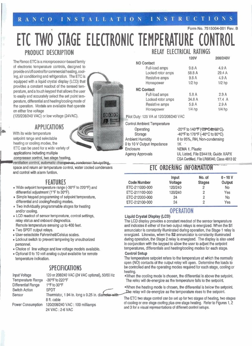
Ranco ETC User manual

~. ,'¢'."~~~,:.:.
RAN C 0 INS TAL L'
.:r·
T'"
I ~0 N
INS T
Rue T ION S
\.
~:
HC TWO ~
PRODUCT DESC
CTRHI TNTROl
TheRa
ofelee
i
em~~bUJe
COOircas,
provide on/off controlfore
ing,airconditioning andrefrigeration. The ETC is
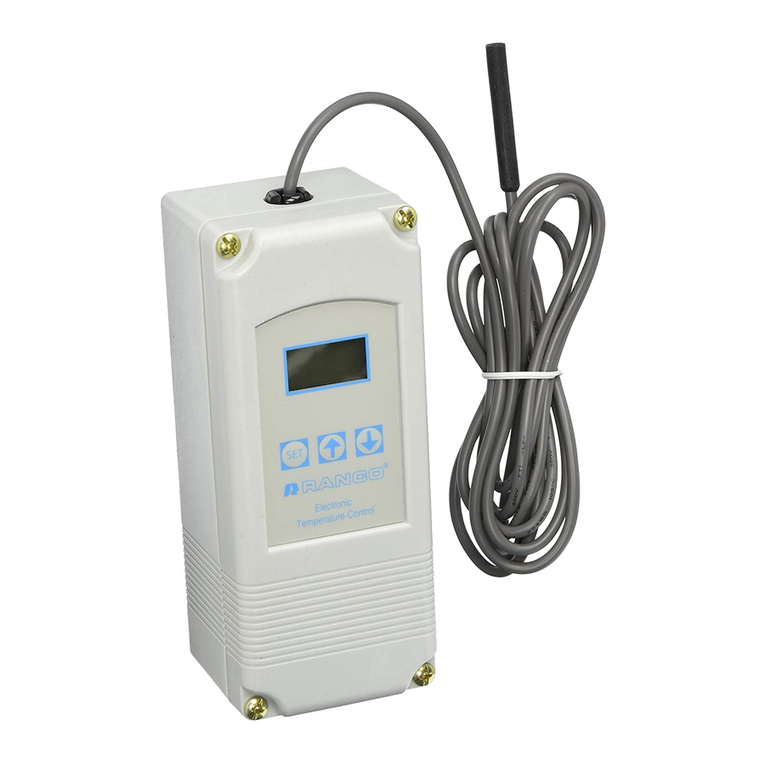
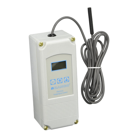
equipped with a liquid crystaldisplay(LCD)that
provides a constantreadout ofthe sensed tem-
perature,and a touch keypad that allowsthe user
to easily and accurately select the set point tem-
perature,differentialand heating/cooling mode of
the operation. Models are available that operate
oneither linevoltage
(120/208/240 VAC)orI
I
NOContact
Full-load amps
Lockedrotor amps
Resistive amps
Horsepower
9.8 A
58.8A
9.8A
1/2 hp
4.9A
29.4 A
4.9A
1/2 hp
.8A
5.8A
1/4 hp
2.9 A
17.4A
2.9A
1/4 hp
-20°Fto140°F (-29OC to 60OC)
-40°Fto 176°F (-40OC to 80OC)
o
to 95%, RH,Non-condensing
mpEldance
1K
EMA1.Plastic
UL·sted.FileE94419,Guide XAPX
CSACertified, FileLR68340,Class 4813 02
compressor control, two stage heating,
/~--ventilation control, automatic changeover,condenser fancycling,
space andreturn air temperature control,water cooledcondensers
Iwith alarm funtion.
FEATURES
•Wide setpoint temperaturerange (-30°F to 220°F) and
differential adjustment(1°Fto 30°F).
•Simple keypad programming ofsetpoint temperature,
differential andcoolinglheating modes.
•Two individually programmable stages for heating
and/orcooling.
•LCD readout of sensor temperature,control settings,
relay status and onboard diagnostics.
•Remote temperature sensing up to 400 feet.
•Two SPOT outputrelays.
•User-selectable Fahrenheit/Celsiusscales.
•Lockout switch to prevent tampering by unauthorized
personnel.
•Choice of line voltage and lowvoltage models available.
•Optional 0to 10 voltanalog output available for remote
temperature indication.
InputNo. of 0-10 V
Code Number Voltage Stages Output
ETC-211000-000 120/240 2 No
ETC-211100-000120/2402Yes
ETC-212000-000242No
ETC·2121 00-000 242Yes
120 or 208/240 VAC (24 VAC optional),50/60 Hz
-30°F to 220°F
1°Fto 30°F
SPOT
Thermistor,1.94 in. long x 0.25 in. diameterwith
8ft. cable
120/208/240 VAC : 100 milliamps
24 VAC:2-6 VAC
OPERATION
Liquid Crystal Display (LCD)
The LCD display provides a constant readout ofthe sensor temperature
and indicates if either ofthe two output relays is energized.When the S1
annunciatoris constantly illuminated during operation, the Stage 1relay is
energized.Likewise,when theS2annunciator is constantly illuminated
during operation,the Stage 2 relay is energized.The display is also used
inconjunction with the keypad to allow the user to adjust the setpoint
temperatures,differentials and heating/cooling modes for each stage.
Control Setup
The temperature setpoint refers tothe temperature at which the normally
open (NO) contactsoftheoutput relay willopen.Determine the loads to
be controlled and the operating modes required foreach stage,cooling or
heating.
•When the coolingmode is chosen,the differential is above the setpoint.
The relay will de-energize as the temperature falls to the setpoint.
•When the heating mode is chosen,the differential is below the setpoint.
The relay will de-energize asthetemperature rises to the setpoint.
The ETC two stage control can be set upfor twostages of heating,two stages
of cooling or one stage cooling plus one stage heating. Refer to Figures 1,2
and 3 for a visual representations of different controlsetups.
Input Voltage
Temperature Range
Differential Range
Switch Action
Sensor

STAGE 1
SETPOINT
STAGE 2
SETPOINT
ON
=
ENERGIZED
OFF
=
DE-ENERGIZED
o
:;;
"T1
m
:D
m
Z
-<
ON~
o
OfF
:;;
"T1
m
~ STAGE 2
~
:;;
r-
ON
(-)
Figure 1:Two Stage Heating Example
STAGE 2
SETPOINT
w
a:
:>
t::
a:
w
Q.
:::<
~
STAGE 1
SETPOINT
ON
=
ENERGIZED
OFF
=
DE-ENERGIZED
o
ON
:;;
"T1
m
:D
m
~
~
STAGE 1
SETPOINT
STAGE 2
SETPOINT
ON
=
ENERGIZED
OFF
=
DE-ENERGIZED
ProgrammingSteps and Display
The ETC two stage can beprogrammedinsevensimple stepsusing the LCD
displayand the three eyseface ofthe control.
programming,press the SET key once to access the
Fahrenheit/Celsius mode.The display will show the current
status,either Ffor degrees Fahrenheit or C for degrees Celsius.
Then press either the up
t
or down.arrow key to toggle
between the For C designation.
Stage 1
Ste2-
Press the SET key again to access the stage 1 setpoint.The
LCD will display the current setpoint and the S1 annunciator will
be blinking on and off to indicate that the control is in the setpoint
mode. Then press either the up
t
key to increase or the down •
key to decrease the setpoint to the desired temperature.
Press the SET key again to access the stage 1 differential.TheLCD will
display the current differential and the DIF 1 annunciator will be
blinking on and off to indicate thatthecontrol is in the differential
mode. Then press eitherthe up
t
keyto increase orthe down •
key to decrease the differentialtothedesired setting.
Press the SET key again to access the stage 1 cooling or heating
mode. The LCD will displaythecurrent mode,either C1 for
cooling or H1 forheating. Thenpress either the up
t
ordown •
key to toggle between the C1 orH1 designation.
Stage 2
Step 5-Press the SET key again to access the stage 2 setpoint.The LCD
will display the current setpoint and the S2 annunciatorwill be
blinking on and off to indicate that the control is in the setpoint
mod,e.Then press either the up
t
key to increase or the down •
key to decrease the setpoint to the desired temperature.
Press the SET keyagaintoaccess the stage 2 differential.The
LCDwill display the current differential and theDIF 2 annunciator
will be blinking on and off to indicate that the control is in the dif-
ferential mode.Then press either the up
t
key to increase or the
down•key to decrease the differential to the desired setting.
Step 7- Press the SETkey again to access the stage 2 cooling or heating
mode.The LCD will display the current mode,either C2 for cool-
ing or H2for heating.Thenpress either the up
t
or down.key
totoggle between the C2 or H2 designation.Press the SET key
once more and programming is complete.
NOTE:TheETCwillautomatically end programming if no keys are
depressed fora periodof thirtyseconds.Any settings that have
been input tothe control willbe accepted at that point.
All controlsettings are etainedin non-volatilememoryifpower to ETC
isinterrupted for anyreason.Re-programming is not necessary
after power outages ordisconnects unless differentcontrol settings
are required.

:=1
-,r,
ILl
sl
II
5';
Lockout Switch
~ 8~is provieJed with -a-lockotJt switch to prevent-tampering--b
unauthorized personnel.Whenplaced in theLOCK position,the
keypad is disabledand nochanges tothesettings canbe made.When
placed in the UNLOCK position,thekeypad will function normally.
To access the lockoutswitch,disconnectthe power supply and open
the control.The switch islocated on theinside cover about 2inches
above the bottom. (see Figure 4).To disablethekeypad,slide the
switch to the left LOCK position.To enable the keypad, slide the
switch to the right UNLOCK position.All ETC controls are shipped
with this switch in the UNLOCK position.
~
LOCK UNLOCK
RELAYRATINGSN.O.IN.C.DISPLAY CODES
VAC120 2081240F FAHRENHEIT
LRA 58N.l4.8 29.4117.4C CELSIUS
FLA 9.815.8 4.912.9 HIHEAT STAGE1
RES A 9.815.8 4.9/2.9Cl COOL STAGE 1
PILOTOUTY125VA H2 HEAT STAGE2
C2 COOLSTAGE 2
f
TEMP INO
&
EP PROBE FAILUREI
OUT OF RANGE
••REGEQUIP52N8 EE EEPROM FAILURE
USECOPPER E1 IMPROPER KEY
CONDUCTORS
ONLYE2 MEMO:Y ERROR
•
TROUBLESHOOTING ERROR MESSAGES
Display essa es
E1· Appears , "
t
ey is pressed when
notin thepre.
To correct: If eE1 essage appears evenwhenno keys are
being pressed,replacethecontrol.
E2· Appearsifthe control settings are not properly stored in memory.
To correct:Check all settings and correct if necessary.
Ep· Appears when the probe is open, shorted or sensing a
temperature thatis out of range.
To correct: Checkto see if the sensed temperatureis outof range.
If not,checkfor probe damagebycomp .g'aownambient
temperaturebetween
-30Of.
e
c::.
eprobeif necessary.
rrupted.
repaired.Replace the control.
eas been entered.
ertothe control for atleast five seconds.
.IeCL message still appears,replace
INSTALLATION INSTRUCTIONS
IMPORTANT
----
1. All ETC series controls are designed as operating controls only. Ifan
operating control failure could result in personal injury or loss of
property,a separate safety control and/or alarm should be installed.
2. The schematic drawings and other information included in
these installation instructions arefor the purpose ofillustration
and general reference only.
3. These instructions do not expand, reduce, modifyoralter the Ranco
Terms in any way; and no warranty or remedy in favorof the customer
or any otherperson arises out of these instructions.
4.Ranco ETC controls have been approved by Underwriters'
Laboratories as UL Listed;however,approval does not extend to
their use forany other purpose.Ranco assumes no responsibility for
any unconventional application of its control unless such application
has been approved in writing by Ranco.
5. It is the responsibility ofthe installer andthe user to assure that his or
its applicationand use ofall Ranco products are in compliance with
allfederal, state andlocal requirements,including,without any
limitation,all requirements imposed underthe National Electric Code
and any applicable building codes.

CAUTION
To preventpossible electrical shock or equipment damage,
disconnect electrical power tothe unit before and during instana-
tion. DO NOT restore electrical powerto unit until the controlis
properly installed and the cover is assembled.DO NOTI
control in an explosive atmosphere as a safety hazard
duetopossible sparkge eralion in the control. Controls are:
to be locatedin areas
siQlriJic:arrt
e.dirtor dust,orina
corrosive explosivealtJn<)Sptl6reon-
ments mayresultin i
j
ry r amage:
.J
(or both)and arelikely
0
shortenthecontrol flOe;
Ranco assumes no responsibility forany such use.
24 VAC INPUT
(OPTIONAL)
. a or any flatsurface using a combinationof any two
_-::::~e slotted holeslocated on the backof the controlcase. The
scomponents are not position sensitive, but should be mounted so
thattheycan be easily wiredand adjusted.Avoid excessive conditions of
moisture,dirt, dust and corrosive atmosphere.
The ETChas provisions for 1/2 inch conduit connections. The conduit hub
should be securedto the conduit before securing the hub to the plastic
housing ofthe control. When using the conduit entry inthe rear ofthe case,
a standard plug should be inserted into the conduit hole in the bottom.
Caution should be exercised not to damage the controlcircuit board or
wiring when installing a conduit connector.
ANALOG OUTPUT
(OPTIONAL)
I~I
I'---~
...,
0.63
-1.15-
2.48
}(h1(::CK-ouTFOR 0.50 DIA
UIT TRADE SIZE
0.50 DIA HOLE CONDUIT
TRADE SIZE .88 REF

Input and Output Wiring
For typical wiring diagrams, refer toFigures 6 an7.
All connections are made tothe power (lower)circuit board. When
the
24
VAC powered models,the
24
VAC input lines mustenter throug e
sidewallof the case.Refer toFigure
5
for location of the entry hole.
Analog Output
ETC models are availablewith anoptional
0
to
10
volt analog output.
This signal is a
Ii
ear
representationof the sensor temperature with
o
volts
=
-30'f
an
=
22 .
Seefigu e
8'
wirigiformation
and Figure 5 I r ut
is desig a
is designa
et6lTlj:>eral:lITl
addffionalcoru'lediOOs
whenexteese e Ie~
supplied with theETC. The sensor cable canbe extendedup to 400 lee.
-amaged sensorcan bereplaced-by splicing a new Rancosensor onto
the sensor leads from thecirCUITboard.The sensor is notpolaritysensitive.
==
----L.
~tX~~
2
I
LINE VOLTAGE
~~I
Figure7:Typical Wiring Diagram for 24 VAC Power Input and
Line Voltage Switching.
+
o
0-10 V
ANALOG OUTPUT
'~~~;"
NC NO C NC C NO
Figure 8:
0.10
V Analog Output Located on Power (Lower) Circuit Board.
fiELD REPAIRS
Field calibrating or repairs to the ETC control must not be attempted.
Sensors and replacement controls are available through Ranco
wholesalers

For spacesensing,mount the sensor where itwill be unaffectedby
heaUcooldischarge or radiated heat sources. Spot sensing requires
the sensor to be in good contact withthe surface being sensed.The
sensor can be inserted in a bulb well for immersion sensing.
CAUTION:
Sensor'tirigs.
control.
DO NOT
attemp' .
board
eade externalfrom the
I.
CAUTION:
Disconnect power tocontrolbeforewiring to avoid
POSSI
e
electrical shock or damage to the controller.
Additional cable can be spliced to the sensor cable to increase the
length beyond the standard 8 feet.It can be extendedup to 400 feet.
Thecable should be at least 22 AWG or larger to keep additional
resistanceaminimum.
All splices 'relengthsadded to the sensor cableshouldbemade
according toa"ablewiring practices and should conform to the
NationalElectriCode and local regulations. Use copper conductors
only.Shielded cableisnotrequired.
1.Before applying power, make sure installation andwiring
connections are correct.
2. Apply power to the controland observe one or more cyclesof
operation.
3. Ifperformanceindicates a problem, check sensor resistance to
determine if sensor or control is at fault.
4. To check sensor resistance, disconnect sensor and measure the
resistance across the leads while measuring temperature atthe
sensor.
Replacement Sensor - Order
Part No.1309007 044
The1309007-044 sensor is a negative temperaturecoefficient (NTC)
thermistor sensor. The sensor resistance decreases with temperature
.increase. It is.25 x 1.94 long with8 feet #22 AWG cable. The
termistor hasareference resistanceof 30,000 ohms at 77°F (25OC).
Theschematic drawings and other information included in these
instructions are for the purpose of illustration and general reference
only. Ranco assumes noresponsiblity forany unconventional
apIica'.co trol,unless suchapplication has beenapproved
._. y
Ranco.
Deg.C.Deg.F. RES. Nom.
-40-40 1,010,000
-30 -22 531,000
-20 -4 291,200
-1014 166,000
0 32 97,960
1050 59,700
206837,470
25 77 30,000
30 86 24,170
40104 15,980
50 122 10,810
60 140 7,464
70 158 5,200
80 176 3,774
90194 2,753
100 212 2,036
110 2301,531
Figure 10:
Resistance
vs Temperature of 1309007·044. Sensor including 8 foot cable.
8115 U.S. Rt.42 N.• Plain City,Oh 43064
~
This manual suits for next models
4
Table of contents
Other Ranco Temperature Controllers manuals
Popular Temperature Controllers manuals by other brands

Johnson Controls
Johnson Controls TE-6800 Series installation guide

AirTouch
AirTouch ZoneTouch3 user manual

MAXTHERMO
MAXTHERMO MC-2438 Operation manual

Bühler technologies
Bühler technologies TF with IO-Link Installation and operation instructions

Automationdirect.com
Automationdirect.com Solo manual

Kasco
Kasco C20 instructions

KEY
KEY RK-2006LPG Operation manual

iNels
iNels RFSTI-11B installation manual

Sea-Bird Scientific
Sea-Bird Scientific SBE 16plus V2 SeaCAT Recorder user manual

RKC INSTRUMENT
RKC INSTRUMENT X-TIO-A instruction manual

Newport
Newport LDT-5500B Series user guide

KT-Elektronik
KT-Elektronik SOL3-3 Quick installation and operating manual