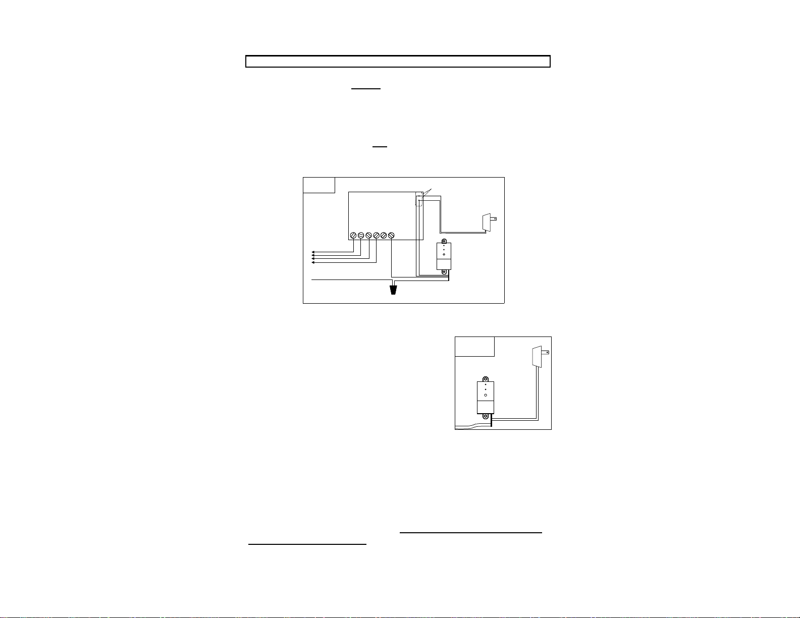
RAIN FALL ADJUSTMENT: (Fig. 8)
The Wireless RainSensor can be adjusted to
detect rainfall quantities of 1/8", 1/4", 1/2",
3/4" or 1". Rotate the cap on the Transmitter
body so the pins are located in the desired rain-
fall amount slot. Be sure to align the slots and
pins properly as this adjustment should not re-
quire excessive force .
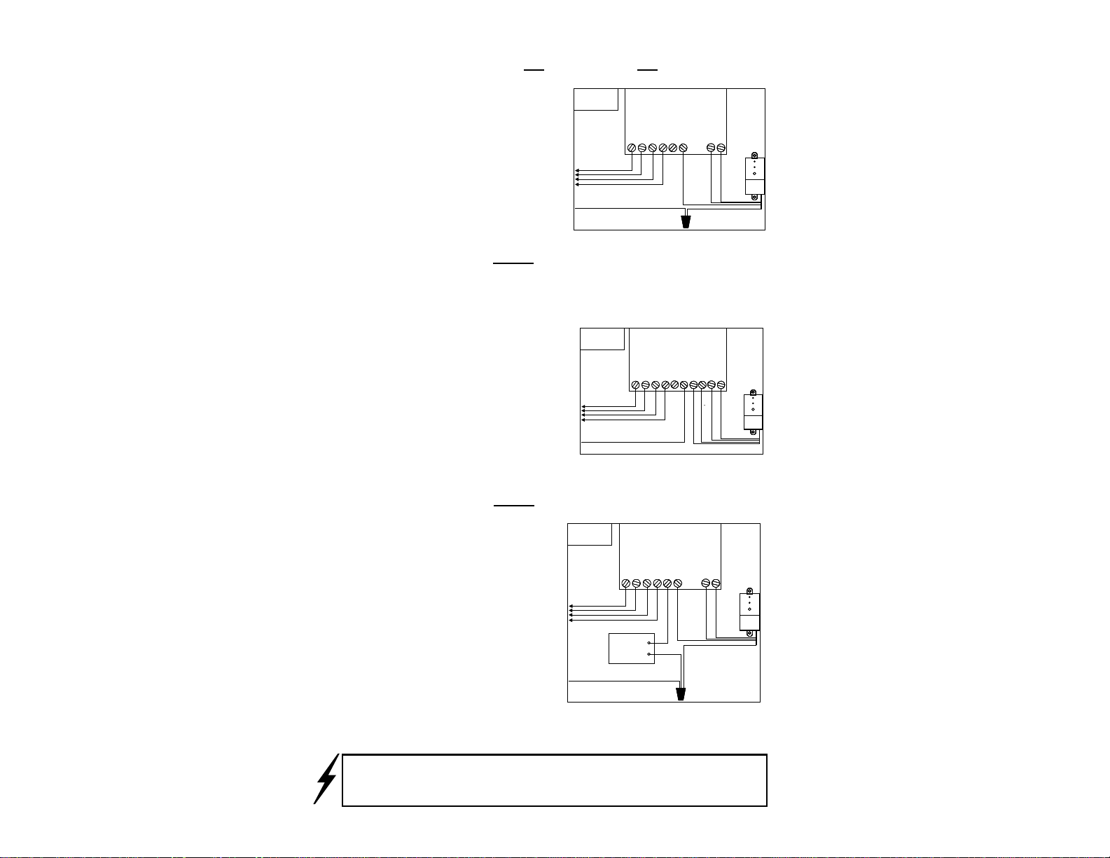
MOUNTING THE TRANSMITTER/SENSOR: (Figs 9, 10, & 11)
Mount the Transmitter as close to the Receiver as possible to avoid inter-
ference of the wireless signal. The Transmitter should be mounted where
it will be exposed to unobstructed rain-
fall, but not in the path of sprinkler
spray. Gutters are ideal locations and
the specially designed bracket makes this
installation as simple as tightening the
supplied thumbscrew under the gutter lip
(see Fig. 9). The Transmitter can also be
mounted on any suitable surface using
the enclosed screws (see Fig. 10). The
Transmitter may also be mounted to a
PVC pipe using a 1-1/4” coupling or optional adapter (Fig. 11). NOTE:
The unit should be mounted in a vertical orientation with the Antenna
wire protruding straight down from the housing,
avoiding installations where the antenna wire comes
in contact with any metal objects.
Prior to final placement, the Transmitter
should be tested again by lightly pressing
& holding the spindle as described in
“Initial Receiver Testing”.
If the Receiver is not visible to
the installer, turn on a watering
zone which is visible from the
installation location and the acti-
vation of the Transmitter will
shut off the “test” zone.
Note: If the location of the Transmitter is not providing a valid signal to
the Receiver, verify the Transmitter operation at close range and choose
another mounting location.
Also, make sure the Antennas are fully extended and straight.
Fig. 8
Fig. 9
5
Fig. 10
TIP!
Fig. 11
1/4
3/4
1/8
1/2
1
ANTENNA