R&M STAGEMAKER SM1 Manual

This document and the information contained herein, is the exclusive property of R&M Materials Handling, Inc., and represents a non-public, confidential and proprietary trade secret that
may not be reproduced, disclosed to third parties, altered or otherwise employed in any manner whatsoever without the express written consent of R&M Materials Handling, Inc.
Copyright © (2010) R&M Materials Handling, Inc. All rights reserved.
INSTALLATION AND
MAINTENANCE MANUAL
STAGEMAKER
®
SM1
English
STD-R-KHA-F-CQD-ENG

SM1 I&M MANUAL/EN/11.16.2010
2/73
This document and the information contained herein, is the exclusive property of R&M MATERIALS HANDLING, INC. and represents a non-public, confidential and proprietary trade
secret that may not be reproduced, disclosed to third parties, altered or otherwise employed in any manner whatsoever without the express written consent of R&M MATERIALS
HANDLING, INC. Copyright © (2010) R&M MATERIALS HANDLING, INC. All rights reserved.
THIS PAGE INTENTIONALLY LEFT BLANK

SM1 I&M MANUAL/EN/11.16.2010
3/73
This document and the information contained herein, is the exclusive property of R&M MATERIALS HANDLING, INC. and represents a non-public, confidential and proprietary trade
secret that may not be reproduced, disclosed to third parties, altered or otherwise employed in any manner whatsoever without the express written consent of R&M MATERIALS
HANDLING, INC. Copyright © (2010) R&M MATERIALS HANDLING, INC. All rights reserved.
mCAUTION: Read the instructions supplied with the product before installation and
commissioning.
mCAUTION: Keep the instructions in a safe place for future reference.
Table of contents
1 INTRODUCTION ........................................................................................................................................ 5
1.1 Contact Information ........................................................................................................................... 5
1.2 Warranty ............................................................................................................................................ 5
1.3 Disclaimer .......................................................................................................................................... 5
1.4 Safety................................................................................................................................................. 6
1.5 Placards and Instructions .................................................................................................................. 8
2 INSTALLATION ......................................................................................................................................... 9
2.1 General .............................................................................................................................................. 9
2.2 Lubrication ......................................................................................................................................... 9
2.3 Mounting .......................................................................................................................................... 10
2.4 Load Hook Throat Opening ............................................................................................................. 11
3 ELECTRICAL CONNECTIONS AND DIAGRAMS.................................................................................. 12
3.1 Control Fuses .................................................................................................................................. 12
3.2 Configuration A – Single-speed – 208 or 230 Volt Connections ..................................................... 13
3.3 Configuration A – Single-speed – 208 or 230 Volt Wiring Diagram ................................................ 14
3.4 Configuration A – Pigtail Pin-out Connections – R&M Standard..................................................... 15
3.5 Configuration B – Single-speed – 208 or 230 Volt Connections ..................................................... 16
3.6 Configuration B – Single-speed – 208 or 230 Volt Wiring Diagram ................................................ 18
3.7 Configuration B – Wiring Labels ...................................................................................................... 19
3.8 Configuration B – Pigtail Pin-out Connections – R&M Standard..................................................... 20
3.9 Configuration C – Single-speed – 208 or 230 Volt Connections ..................................................... 22
3.10 Configuration C – Power Circuit – 208 or 230 Volt Wiring Diagram................................................ 23
3.11 Configuration C – Control Circuit – 208 or 230 Volt Wiring Diagram .............................................. 24
3.12 Configuration C – Wiring Labels ...................................................................................................... 25
3.13 Configuration C – Pigtail Pin-out Connections – R&M Standard..................................................... 26
3.14 Configuration S – Single-speed – 115 Volt Connections ................................................................ 28
3.15 Configuration S – Single-speed – 115 Volt Wiring Diagram............................................................ 29
3.16 Configuration S – Wiring Labels ...................................................................................................... 30
3.17 Configuration S – Pigtail Pin-out Connections – R&M Standard..................................................... 31
3.18 Cable Assemblies ............................................................................................................................ 33
4 INITIAL START-UP.................................................................................................................................. 35
4.1 General ............................................................................................................................................ 35
4.2 Correcting the Direction of Hook Travel .......................................................................................... 35
4.3 Operational Checks – No Load ....................................................................................................... 36
4.4 Operational Checks – With Load ..................................................................................................... 36
5 HOIST OPERATION ................................................................................................................................ 37
6 MAINTENANCE ....................................................................................................................................... 38
6.1 Basic Hoist Construction (Inverted Position) ................................................................................... 38
6.2 Basic Hoist Position (Normal Position) ........................................................................................... 39
6.3 Motor / Body..................................................................................................................................... 40
6.4 Hoist Motor Brake and Load-Limiting Device .................................................................................. 40
6.4.1 Slip Clutch Operation (see Figure 14) ......................................................................................... 40
6.4.2 Slip Clutch Adjustment after Installation ...................................................................................... 42
6.4.3 Hoist Motor Brake Adjustment (see Figure 14) ........................................................................... 43
6.5 Load Chain....................................................................................................................................... 44
6.5.1 General ........................................................................................................................................ 44
6.5.2 Maintenance Inspection............................................................................................................... 44
6.5.3 Load Chain Specifications (see Figure 15).................................................................................. 47

SM1 I&M MANUAL/EN/11.16.2010
4/73
This document and the information contained herein, is the exclusive property of R&M MATERIALS HANDLING, INC. and represents a non-public, confidential and proprietary trade
secret that may not be reproduced, disclosed to third parties, altered or otherwise employed in any manner whatsoever without the express written consent of R&M MATERIALS
HANDLING, INC. Copyright © (2010) R&M MATERIALS HANDLING, INC. All rights reserved.
6.5.4 Removing the Load Chain ........................................................................................................... 47
6.5.5 Installing the Load Chain ............................................................................................................. 48
6.6 Fall Stop Assembly .......................................................................................................................... 50
6.6.1 General ........................................................................................................................................ 50
6.6.2 Fall Stop Installation .................................................................................................................... 50
6.7 Chain Container............................................................................................................................... 51
6.8 Limit Switches.................................................................................................................................. 52
6.8.1 Upper and Lower Travel Safety Limit Switch............................................................................... 52
6.8.2 Rotary Geared Limit Switch ......................................................................................................... 53
6.9 Brake Coil Specifications ................................................................................................................. 54
6.10 SM1 Motor Data............................................................................................................................... 55
6.11 Hooks............................................................................................................................................... 56
6.11.1 General .................................................................................................................................... 56
6.11.2 Inspection................................................................................................................................. 57
6.11.3 Hook Dimensions and Specifications ...................................................................................... 57
6.11.4 Body Hook (Normal Position) .................................................................................................. 58
7 PREVENTATIVE MAINTENANCE .......................................................................................................... 59
7.1 Maintenance and Inspection Table.................................................................................................. 59
7.2 Lubrication ....................................................................................................................................... 60
7.2.1 Load Chain Cleaning and Lubrication ......................................................................................... 60
7.3 Recommended Technical Support for Various Spare Parts............................................................ 61
7.4 Torque (lb-ft) Specifications for Fasteners ...................................................................................... 61
7.5 Troubleshooting ............................................................................................................................... 62
8 PARTS ILLUSTRATION .......................................................................................................................... 64
8.1 Hoist Body (NORMAL position shown)............................................................................................ 64
8.2 Helical Gear Mechanism & Brake.................................................................................................... 66
8.3 Lifting Assembly............................................................................................................................... 68
8.4 Control Panel Assembly – Configuration A ..................................................................................... 70
8.5 Control Panel Assembly – Configuration B & C .............................................................................. 71
8.6 Control Panel Assembly – Configuration S ..................................................................................... 72
8.7 SM1 Pigtail Connectors ................................................................................................................... 73
8.8 Pickle Assembly............................................................................................................................... 73

SM1 I&M MANUAL/EN/11.16.2010
5/73
This document and the information contained herein, is the exclusive property of R&M MATERIALS HANDLING, INC. and represents a non-public, confidential and proprietary trade
secret that may not be reproduced, disclosed to third parties, altered or otherwise employed in any manner whatsoever without the express written consent of R&M MATERIALS
HANDLING, INC. Copyright © (2010) R&M MATERIALS HANDLING, INC. All rights reserved.
1 INTRODUCTION
1.1 Contact Information
Please do not hesitate to use the following contact information in the event that you may need assistance:
R&M MATERIALS HANDLING, INC.
4501 Gateway Boulevard
Springfield, OH 45502
General Telephone: 937 - 328-5100
Toll Free Telephone (US): 800 - 955-9967
General Fax: 937 - 325-5319
Parts Department Fax (US): 800 - 955-5162
Parts Dept. Fax (other): 937 - 328-5162
Website: www.rmhoist.com
1.2 Warranty
All sales are subject to the R&M Materials Handling, Inc. Standard Terms and Conditions of Sale (Revision
101707), a copy of which is available at www.rmhoist.com or upon request from R&M Materials Handling,
Inc. customer service/sales representatives and the terms of which are incorporated as if fully rewritten
herein.
1.3 Disclaimer
This manual has been prepared by R&M MATERIALS HANDLING, INC. to provide information and
suggestions for hoist installation, maintenance, and inspection personnel. This manual should be used in
conjunction with the
STAGEMAKER
®COMPACT Concert Hoist Operator’s Manual to teach safe operating
practices to all personnel associated with hoist operations and maintenance.
It is NOT intended that the recommendations in this manual take precedence over existing plant / site safety
rules and regulations or OSHA regulations. However, a thorough study of the following information should
provide a better understanding of proper installation, maintenance, and inspection procedures that are to be
followed in order to afford a greater margin of safety for people and machinery in the area of hoist
operations.
It must be recognized that this is a manual of recommendations for the Hoist Installation, Maintenance, and
Inspection personnel and its use is permissive, not mandatory. It is the responsibility of the hoist owner to
make personnel aware of all federal, state, and local codes and regulations. The owner is responsible for
providing instruction and ensuring that certain installation, maintenance, and inspection personnel are
properly trained.

SM1 I&M MANUAL/EN/11.16.2010
6/73
This document and the information contained herein, is the exclusive property of R&M MATERIALS HANDLING, INC. and represents a non-public, confidential and proprietary trade
secret that may not be reproduced, disclosed to third parties, altered or otherwise employed in any manner whatsoever without the express written consent of R&M MATERIALS
HANDLING, INC. Copyright © (2010) R&M MATERIALS HANDLING, INC. All rights reserved.
1.4 Safety
Read and understand this manual before using the hoist.
Important issues to remember during installation, operation, maintenance, and inspection are provided at the
hoist control stations, at various locations on the hoist, in this manual, and in the STAGEMAKER®
COMPACT Concert Hoist Operator’s Manual. These issues are indicated by DANGER, WARNING, or
CAUTION instructions or placards that alert personnel to potential hazards, proper operation, load
limitations, and more.
m
DANGER: Indicates an imminently hazardous situation, which, if not avoided, will result in death
or serious injury.
m
WARNING: Indicates a potentially hazardous situation, which, if not avoided, could result in death
or serious injury.
m
CAUTION: Indicates a potentially hazardous situation, which, if not avoided, may result in minor
or moderate injury. It may also be used to alert against unsafe practices.
Taking precedence over any specific rule, however, is the most important rule of all:
“USE COMMON SENSE”
It is a responsibility of the hoist owner / user to establish programs to:
1. Train and designate hoist operators, and
2. Train and designate hoist inspectors / maintenance personnel.

SM1 I&M MANUAL/EN/11.16.2010
7/73
This document and the information contained herein, is the exclusive property of R&M MATERIALS HANDLING, INC. and represents a non-public, confidential and proprietary trade
secret that may not be reproduced, disclosed to third parties, altered or otherwise employed in any manner whatsoever without the express written consent of R&M MATERIALS
HANDLING, INC. Copyright © (2010) R&M MATERIALS HANDLING, INC. All rights reserved.
The words SHALL and SHOULD are used throughout this manual in accordance with definitions in the
ASME B30 standards as follows:
SHALL indicates a rule is mandatory and must be followed.
SHOULD indicates a rule is a recommendation, the advisability of which depends on the facts
in each situation.
Hoist operation, hoist inspection, and hoist maintenance personnel training programs should be based on
requirements in accordance with the latest edition of:
ASME B30.16 Safety Standard for Overhead Hoists (Underhung)
NOTE: When using the
STAGEMAKER
®COMPACT Concert Hoist in the Inverted position,
ASME B30.16 Section 16-0.1 states that this ASME standard does not apply when “drawing both
the load and the hoist up or down the load chain(s) or rope(s) of the hoist.” See WARNING below.
Such training should also provide information for compliance with any Federal, State, or Local Code
requirements, and existing plant safety rules and regulations.
If an overhead hoist is installed as part of an overhead crane or monorail system, training programs should
also include requirements in accordance with the latest editions, as applicable, of:
•ASME B30.11 Safety Standard for Monorails and Underhung Cranes
•ASME B30.17 Safety Standard for Overhead and Gantry Cranes, Top Running Bridge,
Single Girder, Underhung Hoist.
NOTE: It is a responsibility of the owner / user to install, inspect, test, maintain, and operate a
hoist in accordance with the ASME B30.16 Safety Standard, OSHA Regulations, and ANSI /
NFPA 70, National Electric Code. If the hoist is installed as part of a total lifting system, it is also
the responsibility of the owner / user to comply with the applicable ASME B30 volume that
addresses other types of equipment used in the system.
NOTE: Further, it is the responsibility of the owner / user to require that all personnel who will
install, inspect, test, maintain, and operate a hoist read the contents of this manual,
STAGEMAKER® COMPACT Concert Hoist Operator’s Manual, ASME B30.16 Safety Standards
for Overhead Hoists (Underhung), OSHA Regulations, and ANSI / NFPA 70, National Electric
Code. If the hoist is installed as part of a total lifting system, all personnel must also read the
applicable ASME B30 volume that addresses other types of equipment used in the system.
m
WARNING: Failure to read and comply with any one of the limitations noted in this manual
can result in product failure, serious bodily injury or death, and / or property damage.

SM1 I&M MANUAL/EN/11.16.2010
8/73
This document and the information contained herein, is the exclusive property of R&M MATERIALS HANDLING, INC. and represents a non-public, confidential and proprietary trade
secret that may not be reproduced, disclosed to third parties, altered or otherwise employed in any manner whatsoever without the express written consent of R&M MATERIALS
HANDLING, INC. Copyright © (2010) R&M MATERIALS HANDLING, INC. All rights reserved.
R&M MATERIALS HANDLING, INC. has no direct involvement or control over the hoist’s operation and
application. Conforming to good safety practices is the responsibility of the owner, user, and operating
personnel.
Only those Authorized and Qualified Personnel who have shown that they have read and have understood
this manual and the STAGEMAKER® COMPACT Concert Hoist Operator’s Manual should be permitted
to operate the hoist.
The owner / user SHALL ensure that all Operators read and understand the STAGEMAKER® COMPACT
Concert Hoist Operator’s Manual prior to operating the hoist.
1.5 Placards and Instructions
READ and OBEY all Danger, Warning, Caution, and Operating Instructions on the hoist and in this manual
and STAGEMAKER® COMPACT Concert Hoist Operator’s Manual. Make sure that all placards are in
place and legible.
Failure to comply with safety precautions in this manual and on the hoist is a safety violation that may result
in serious injury, death, or property damage.

SM1 I&M MANUAL/EN/11.16.2010
9/73
This document and the information contained herein, is the exclusive property of R&M MATERIALS HANDLING, INC. and represents a non-public, confidential and proprietary trade
secret that may not be reproduced, disclosed to third parties, altered or otherwise employed in any manner whatsoever without the express written consent of R&M MATERIALS
HANDLING, INC. Copyright © (2010) R&M MATERIALS HANDLING, INC. All rights reserved.
2 INSTALLATION
m
DANGER: Before installing, removing, inspecting, or performing any maintenance on a
hoist, the main switch shall be de-energized. Lock and tag the main switch in the de-
energized position in accordance with ANSI Z244.1. Follow other maintenance procedures
outlined in this manual and ASME B30.16.
2.1 General
Prior to installation, the unit shall be checked thoroughly for damage during shipment or handling at the job
site.
Each complete electric chain hoist is load tested at the factory at 125% of the nameplate-rated capacity.
All hoists are designed for the type of mounting specified by the purchaser. The adequacy of the supporting
members (monorail beams, cranes, hangers, supports, framing, etc.) is the responsibility of user / owner and
shall be determined or verified by qualified personnel.
Read the instructions contained in this manual and the STAGEMAKER® COMPACT Concert Hoist
Operator’s Manual as well as any other related manuals. Observe the warning tags attached to the unit
before the installation is started.
2.2 Lubrication
The hoist gear case comes completely pre-lubricated with grease. The load chain requires lubrication prior to
first use. Chain lubricant is included with shipment of each new chain hoist.

SM1 I&M MANUAL/EN/11.16.2010
10/73
This document and the information contained herein, is the exclusive property of R&M MATERIALS HANDLING, INC. and represents a non-public, confidential and proprietary trade
secret that may not be reproduced, disclosed to third parties, altered or otherwise employed in any manner whatsoever without the express written consent of R&M MATERIALS
HANDLING, INC. Copyright © (2010) R&M MATERIALS HANDLING, INC. All rights reserved.
2.3 Mounting
Below are the basic mounting positions for
STAGEMAKER
® COMPACT Concert Hoists:
Figure 1. Inverted Mounting and Normal Mounting
INVERTED
(us
ually associated with a temporary installation)
NORMAL
(usually associated with a permanent installation)
mWARNING:
Do not use hoist to lift people or suspend loads over people.
Do not leave a freely suspended load on hoist unattended.
A suspended load must always be tied off using appropriate chains, cables or other redundant load
bearing means before access to the area beneath the load is permitted (1).
Failure to do so could result in property damage, death or serious injury to personnel.
(1) If the load cannot be tied off due to the nature of the application, redundancies and/or advanced safety
features, including but not limited to multiple/redundant hoists, dual brakes on the hoist, a minimum ten
to one safety factor on load bearing components, load monitoring devices, etc. used either individually
or, as circumstances dictate, in conjunction with one another, must be incorporated into the design of the
system.

SM1 I&M MANUAL/EN/11.16.2010
11/73
This document and the information contained herein, is the exclusive property of R&M MATERIALS HANDLING, INC. and represents a non-public, confidential and proprietary trade
secret that may not be reproduced, disclosed to third parties, altered or otherwise employed in any manner whatsoever without the express written consent of R&M MATERIALS
HANDLING, INC. Copyright © (2010) R&M MATERIALS HANDLING, INC. All rights reserved.
2.4 Load Hook Throat Opening
mCAUTION: ANSI B30.16-1998 recommends that the throat opening of a load hook be measured
and recorded prior to putting a hoist into service and that a gauge be made to provide a quick
visual inspection for a bent hook as required during routine inspections. Record this
information before initial start-up. See section 6.11 for more detailed hook information.

SM1 I&M MANUAL/EN/11.16.2010
12/73
This document and the information contained herein, is the exclusive property of R&M MATERIALS HANDLING, INC. and represents a non-public, confidential and proprietary trade
secret that may not be reproduced, disclosed to third parties, altered or otherwise employed in any manner whatsoever without the express written consent of R&M MATERIALS
HANDLING, INC. Copyright © (2010) R&M MATERIALS HANDLING, INC. All rights reserved.
3 ELECTRICAL CONNECTIONS AND DIAGRAMS
The user / owner must provide the main power supply hardware (cable, conductor bar, fuses, disconnect
switch, etc.).
mCAUTION: Make sure that the power supply voltage is the same as that shown on hoist serial
plate / nameplate.
mCAUTION: Make sure that fuses and other current overload devices are in place to protect the
power supply.
mCAUTION: Make sure that power cable or conductors have sufficient capacity to maintain the
hoist supply voltage by ±5 percent of nominal voltage under all operating conditions. Poor
voltage regulation may cause motor overheating or sluggishness, and chattering / inoperative
motor brake(s) and controls.
mCAUTION: Do not use power supply cables with solid conductors.
mWARNING: Failure to properly ground the hoist presents the danger of electric shock.
mWARNING: An improper or insufficient ground connection creates an electrical shock hazard
when touching any part of the hoist or trolley.
mDANGER: Before installing, removing, inspection, or performing any maintenance on a hoist,
the main switch shall be de-energized. Lock and tag the main switch in the de-energized position in
accordance with ANSI Z244.1. Follow other maintenance procedures outlined in this manual and
ASME B30.16.
3.1 Control Fuses
The control fuse holder for the single-phase 115 volt control panels is installed as a wire mounted in-line fuse
holder. The in-line housing separates for fuse replacement. The control fuse holders for hoists with three
phase power supplies are cylindrical and mounted to the printed circuit control boards (labeled F100).
POWER CONTROL FUSE
SUPPLY VOLTAGE SIZE
3 – PHASE 115 VAC 500 mA
3 – PHASE 48 VAC 630 mA
1 – PHASE 115 VAC 250 mA
SM1 I&M MANUAL/EN/11.16.2010
13/73
This document and the information contained herein, is the exclusive property of R&M MATERIALS HANDLING, INC. and represents a non-public, confidential and proprietary trade
secret that may not be reproduced, disclosed to third parties, altered or otherwise employed in any manner whatsoever without the express written consent of R&M MATERIALS
HANDLING, INC. Copyright © (2010) R&M MATERIALS HANDLING, INC. All rights reserved.
3.2 Configuration A – Single-speed – 208 or 230 Volt Connections
Configuration A utilizes direct connection of a three-phase 208 or 230 volt main power supply to the hoist
motor leads via a terminal strip. A motor brake rectifier circuit board (ACF) is provided to operate the D.C.
hoist motor brake assembly.
Figure 2. Configuration A Connections
The SM1 three-phase motor is only available as a two-speed. Therefore, the above layout shows the
connection of the high-speed motor leads and motor brake coil leads to the ACF direct control board.
The connections are the same for both 208 Volts and 230 Volts. The brake coil supply voltage from the AFC
brake control card is 90 - 100 volts DC for both 208 Volts and 230 Volts.
1U
1U
PE
1W
1V
1V
1W
1U
1V
1W
PE
2W
2V
2U
T1
TRANSFORMER
2U
2V
2W
2U
2V
(+)
(-)
(-)
#1
BRAKE
#2
BRAKE
OPT.
MOTOR
LEADS
2U
2V
2W
L1
L2
L3
PE
SINGLE-SPEED CONNECTIONS FOR
SM1 TWO-SPEED MOTOR
208/230V – 3 PHASE
BRAKE
LEADS
ACF
CARD
POWER
SUPPLY
(+)
SM1 I&M MANUAL/EN/11.16.2010
14/73
This document and the information contained herein, is the exclusive property of R&M MATERIALS HANDLING, INC. and represents a non-public, confidential and proprietary trade
secret that may not be reproduced, disclosed to third parties, altered or otherwise employed in any manner whatsoever without the express written consent of R&M MATERIALS
HANDLING, INC. Copyright © (2010) R&M MATERIALS HANDLING, INC. All rights reserved.
3.3 Configuration A – Single-speed – 208 or 230 Volt Wiring Diagram
Figure 3. Configuration A – Single-speed – 208 or 230 Volt Wiring Diagram
L1
L2
PE
2U
2V
2W
1W
1U
1V
MOTOR
D8
PE
MOTOR
LEADS
NOT IN
USE:
1U
1V
1W
AFC
CONTROL
L3
X1:
OPTIONAL BRAKE #2
DELAYED
2V
X5:
PE
POWER
LEADS
V6
D9
D7
(-)
(+)
(-)
(+)
V4
V3
V1
V2
BRAKE #1
2W 2U

SM1 I&M MANUAL/EN/11.16.2010
15/73
This document and the information contained herein, is the exclusive property of R&M MATERIALS HANDLING, INC. and represents a non-public, confidential and proprietary trade
secret that may not be reproduced, disclosed to third parties, altered or otherwise employed in any manner whatsoever without the express written consent of R&M MATERIALS
HANDLING, INC. Copyright © (2010) R&M MATERIALS HANDLING, INC. All rights reserved.
3.4 Configuration A – Pigtail Pin-out Connections – R&M Standard
Table 1. POWER ONLY – PIGTAIL WITH PLUG
WIRE COLOR
AWG 12 – 4 COND
CONTROL PANEL
CONNECTIONS
MALE CE PLUG
BLUE (ME420P9)
PIN NUMBER
TWIST LOCK
MALE PLUG (L16-20P)
3 POLE + GRD
BLACK L1 1 X
WHITE L2 2 Y
RED L3 3 Z
GREEN PE (GROUND) PE (GROUND) G
Table 2. WIRING DIAGRAM LABELS
CODE DESCRIPTION
L1 POWER SUPPLY – PHASE ONE
L2 POWER SUPPLY – PHASE TWO
L3 POWER SUPPLY – PHASE THREE
PE GROUND
(-) MOTOR BRAKE COIL SUPPLY – VOLTS DC
(+) MOTOR BRAKE COIL SUPPLY – VOLTS DC
1W MOTOR LEAD W – SLOW
2W MOTOR LEAD W – FAST
1U MOTOR LEAD U – SLOW
2U MOTOR LEAD U – FAST
1V MOTOR LEAD V – SLOW
2V MOTOR LEAD V – FAST
mCAUTION: The above pin-out connections reflect R&M’s standard connections. There are no
industry standards for the above pin connections. Always check the wiring of any equipment before
applying power.

SM1 I&M MANUAL/EN/11.16.2010
16/73
This document and the information contained herein, is the exclusive property of R&M MATERIALS HANDLING, INC. and represents a non-public, confidential and proprietary trade
secret that may not be reproduced, disclosed to third parties, altered or otherwise employed in any manner whatsoever without the express written consent of R&M MATERIALS
HANDLING, INC. Copyright © (2010) R&M MATERIALS HANDLING, INC. All rights reserved.
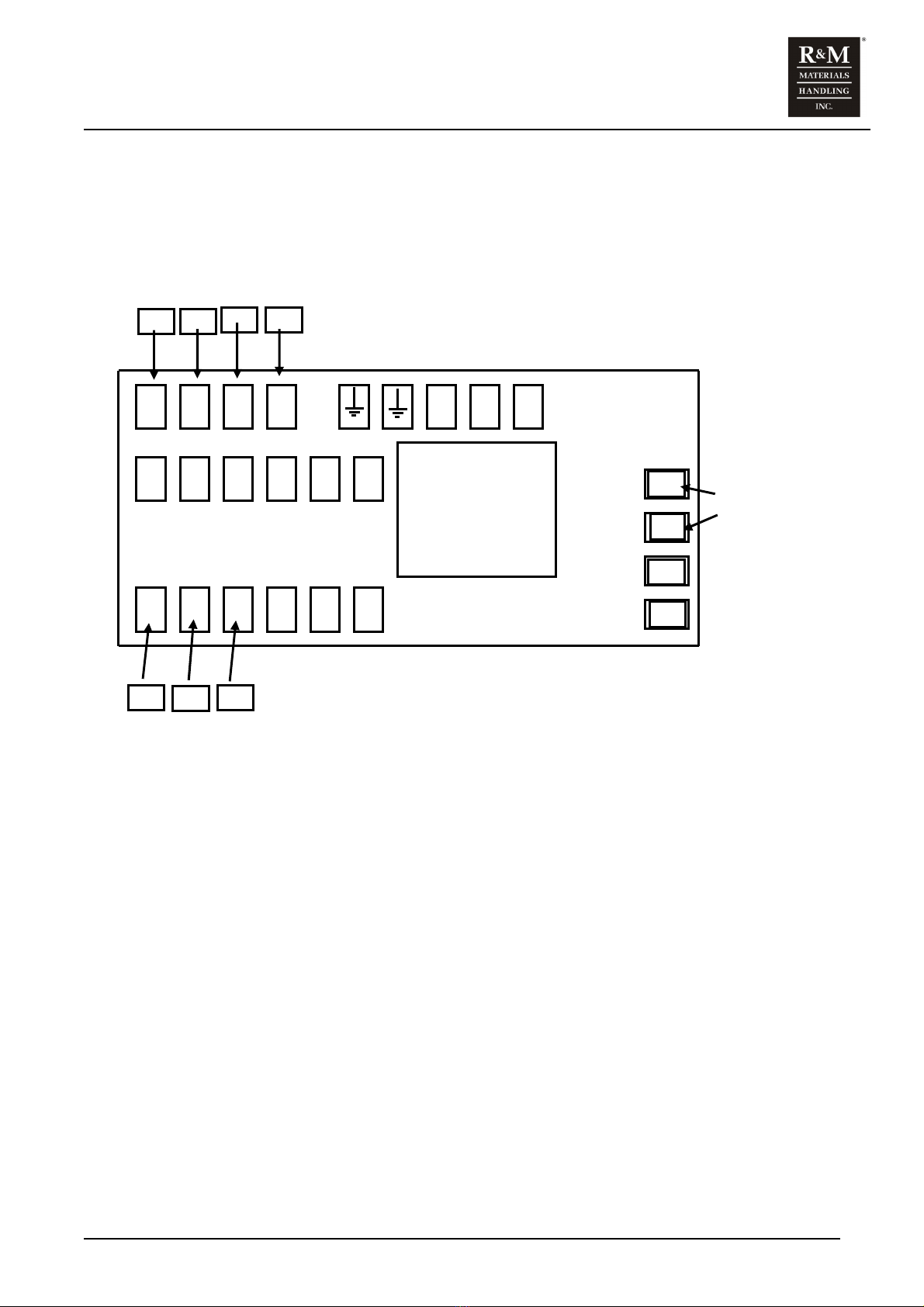
3.5 Configuration B – Single-speed – 208 or 230 Volt Connections
NOTE: THIS CONTROL IS NOT RECONNECTABLE!
Figure 4. Configuration B – Single-speed – 208 or 230 Volt Connections
The SM1 can only be connected to the specific voltage noted on the hoist serial tag. The SM1 three-phase
motor is only available as a two-speed motor. The single-speed SM1 offering is obtained by connecting the
high-speed motor leads of the two-speed motor.
The fuse holder, F100, is located as indicated on the control panel layout. The fuse is easily removed by
loosening the top of the cylindrical holder.
F100
( + )
( - )
BRAKE
COIL
2W
2V
1U
2U
T100

SM1 I&M MANUAL/EN/11.16.2010
17/73
This document and the information contained herein, is the exclusive property of R&M MATERIALS HANDLING, INC. and represents a non-public, confidential and proprietary trade
secret that may not be reproduced, disclosed to third parties, altered or otherwise employed in any manner whatsoever without the express written consent of R&M MATERIALS
HANDLING, INC. Copyright © (2010) R&M MATERIALS HANDLING, INC. All rights reserved.
THIS PAGE INTENTIONALLY LEFT BLANK
SM1 I&M MANUAL/EN/11.16.2010
18/73
This document and the information contained herein, is the exclusive property of R&M MATERIALS HANDLING, INC. and represents a non-public, confidential and proprietary trade
secret that may not be reproduced, disclosed to third parties, altered or otherwise employed in any manner whatsoever without the express written consent of R&M MATERIALS
HANDLING, INC. Copyright © (2010) R&M MATERIALS HANDLING, INC. All rights reserved.
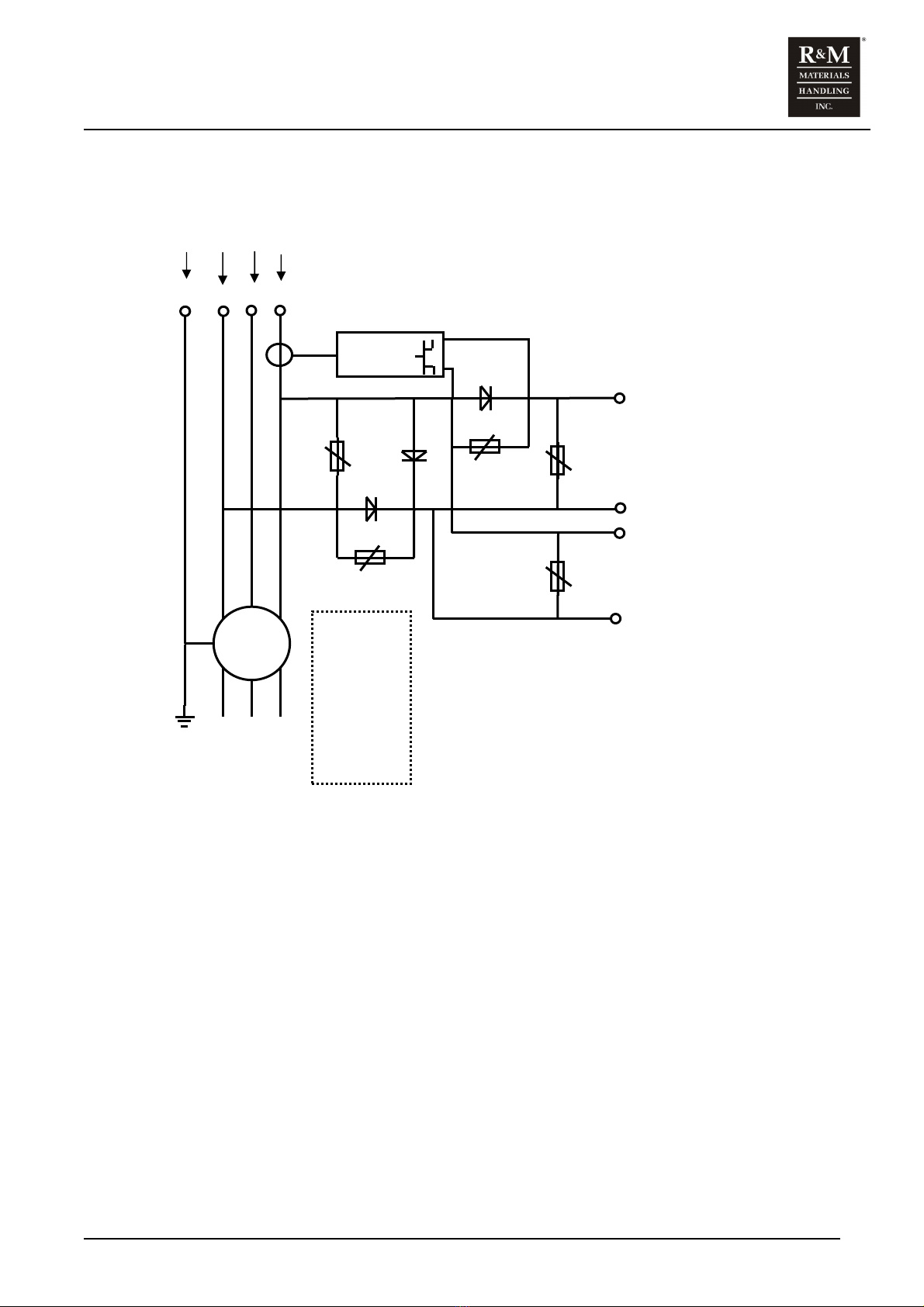
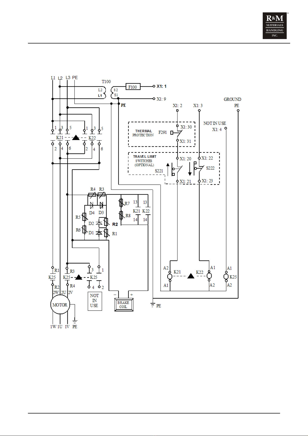
3.6 Configuration B – Single-speed – 208 or 230 Volt Wiring Diagram
Figure 5. Configuration B – Single-speed – 208 or 230 Volt Wiring Diagram

SM1 I&M MANUAL/EN/11.16.2010
19/73
This document and the information contained herein, is the exclusive property of R&M MATERIALS HANDLING, INC. and represents a non-public, confidential and proprietary trade
secret that may not be reproduced, disclosed to third parties, altered or otherwise employed in any manner whatsoever without the express written consent of R&M MATERIALS
HANDLING, INC. Copyright © (2010) R&M MATERIALS HANDLING, INC. All rights reserved.
3.7 Configuration B – Wiring Labels
Table 3. Configuration B – Wiring Labels
CODE DESCRIPTION
L1 POWER SUPPLY – PHASE ONE
L2 POWER SUPPLY – PHASE TWO
L3 POWER SUPPLY – PHASE THREE
PE GROUND
(-) MOTOR BRAKE COIL SUPPLY – VOLTS DC
(+) MOTOR BRAKE COIL SUPPLY – VOLTS DC
1W MOTOR LEAD W – SLOW
2W MOTOR LEAD W – FAST
1V MOTOR LEAD V – SLOW
2V MOTOR LEAD V – FAST
1U2U MOTOR LEAD U
K21 UP CONTACTOR
K22 DOWN CONTACTOR
K25 FAST CONTACTOR - (NOT IN USE)
T100 CONTROL TRANSFORMER
F100 CONTROL CIRCUIT FUSE
S221/S222 TRAVEL LIMIT SWITCHES (OPTIONAL)
F291 THERMAL PROTECTION SWITCH
X1 – 1 TERMINAL STRIP – CONTROL VOLTAGE SUPPLY - HOT
X1 – 2 TERMINAL STRIP – HOIST UP CONNECTION
X1 – 3 TERMINAL STRIP – HOIST DOWN CONNECTION
X1 – 4 TERMINAL STRIP – HOIST FAST CONNECTION - (NOT IN USE)
X1 – 9 TERMINAL STRIP – CONTROL NEUTRAL
X1 – 30, 31 TERMINAL STRIP – MOTOR THERMAL CONNECTIONS
X1 – 21, 22 TERMINAL STRIP – UPPER LIMIT SWITCH CONNECTIONS
X1 – 23, 24 TERMINAL STRIP – LOWER LIMIT SWITCH CONNECTIONS

SM1 I&M MANUAL/EN/11.16.2010
20/73
This document and the information contained herein, is the exclusive property of R&M MATERIALS HANDLING, INC. and represents a non-public, confidential and proprietary trade
secret that may not be reproduced, disclosed to third parties, altered or otherwise employed in any manner whatsoever without the express written consent of R&M MATERIALS
HANDLING, INC. Copyright © (2010) R&M MATERIALS HANDLING, INC. All rights reserved.
3.8 Configuration B – Pigtail Pin-out Connections – R&M Standard
Table 4. POWER ONLY – PIGTAIL WITH PLUG
WIRE COLOR
AWG 12 – 4 COND
CONTROL PANEL
CONNECTIONS
TWIST LOCK
MALE PLUG (L16-20P)
3 POLE + GRD
BLACK L1 X
WHITE L2 Y
RED L3 Z
GREEN PE (GROUND) G
Table 5. CONTROL ONLY – PIGTAIL WITH PLUG
WIRE COLOR
AWG 16 – 7 COND
CONTROL PANEL
CONNECTIONS
TWIST LOCK
FEMALE RECEPTACLE
(L14-20R)
3 POLE + GRD
ORANGE UP W
BLUE COMMON X
BLACK on WHITE DOWN Y
GREEN GROUND G
Table 6. POWER AND CONTROL – 7 PIN – PIGTAIL WITH PLUG
WIRE COLOR
AWG 12 – 4 COND
CONTROL PANEL
CONNECTIONS
MALE PLUG - SOCAPEX 7 PIN
(SX07LF)
PIN NUMBER
BLACK L1 1
WHITE L2 2
RED L3 3
ORANGE UP 4
GREEN PE (GROUND) 5
BLUE COMMON 6
BLACK on WHITE DOWN 7
Other manuals for STAGEMAKER SM1
1
Table of contents
Other R&M Industrial Equipment manuals


