13
N4300(LLM), N5300
N6300 N4950(LLM),
N5450 N5450CS N6450
LJ6VH
N4000(LLM), N5000 N5000CS N6000
19
17
18
20
14
15
16
14
15
INSTRUCCIONES
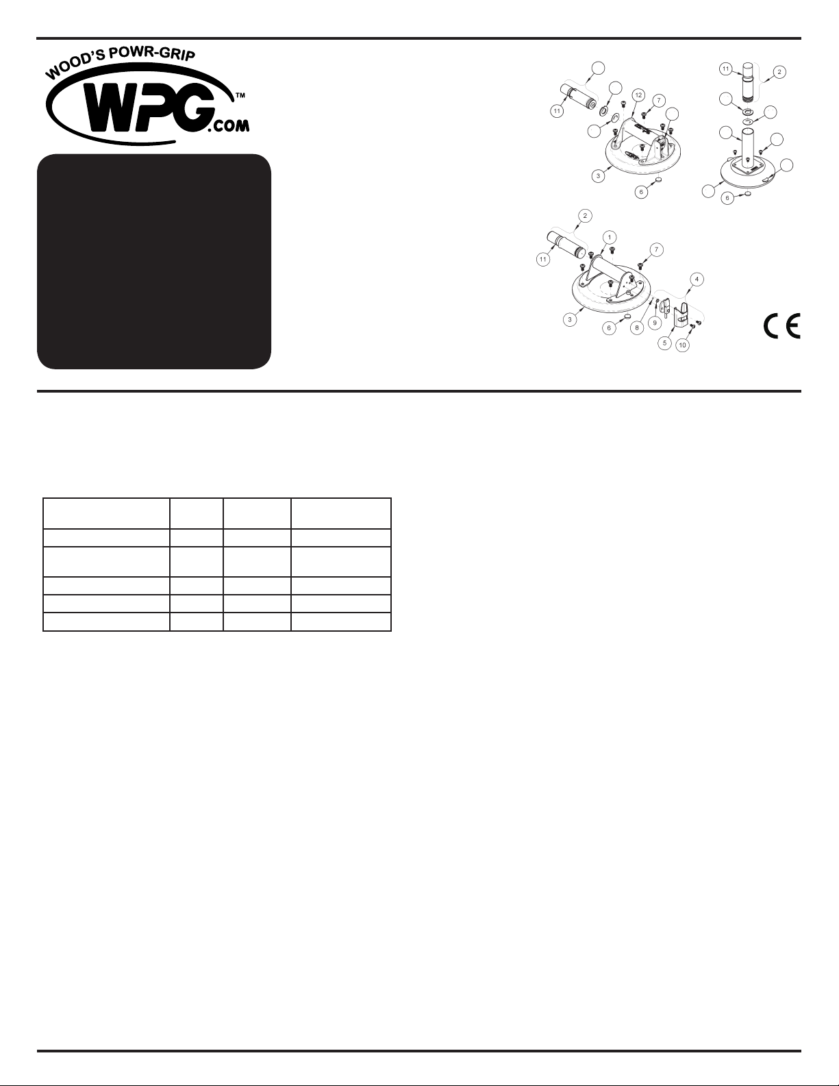
Modelo LJ6VH
Modelos N4000(LLM) N5000 N6000
Modelos N4300(LLM) N5300 N6300
Modelos N4950(LLM) N5450 N6450
Modelos N5450CS N5000CS
CARACTERÍSTICAS TÉCNICAS
Descripción de los productos
Las ventosas de mano utilizan el vacío para levantar y llevar las cargas, como
se indica a continuación: Una bomba manual extrae el aire de entre el disco de
goma y la supercie de contacto; una línea roja en el émbolo de la bomba sirve
como indicador de vacío; una válvula de retención permite que el usuario vuelva
a bombear la ventosa sin quitarla de la supercie de contacto; y un mecanismo
de desprendimiento permite que la ventosa se desprenda por completo.
*La Máxima capacidad de carga incluye un factor de seguridad de 3:1 y requiere
lo siguiente: la adherencia en las supercies que son planas, limpias, lisas y
no porosas; un mínimo nivel de vacío de 17½" Hg [-59 kPa]; y un coeciente
de fricción de 1. Este cálculo se basa en las pruebas de las ventosas de mano
nuevas que están adheridas en la supercie horizontal superior de los objetos
estáticos en las condiciones ideales. Muchos factores pueden reducir la
capacidad, tales como: levantar una carga cuando la ventosa está adherida en
una supercie vertical o inclinada; levantar una carga que ejerce la fuerza de
palanca en la ventosa. Véase www.WPG.com para más información.
Condiciones de la carga y Condiciones ambientales
Use la ventosa en las supercies limpias, relativamente lisas y no porosas,
en las temperaturas desde 10° hasta 120° Fahrenheit [desde -12° hasta 49°
Celsius]. Los líquidos o los contaminantes pueden reducir la resistencia de la
ventosa contra deslizarse. Es posible que el indicador con línea roja no funcione
ablemente en las elevaciones arriba de 5000 pies [1524 metros]; véase Servicio.
FUNCIONAMIENTO
Adherir
1) Ponga la ventosa de mano en la supercie de contacto de manera que la línea
roja sea visible si aparece mientras que usted levanta la carga.
PRECAUCIÓN: Pruebe la ventosa en las supercies de colores claros o de
revestimientos delicados, para asegurarse de que no cause ni manchas ni
deformidades de la carga.
2) Bombee el émbolo hasta que la ventosa se adhiere por completo. Cuando la
línea roja está escondida, el vacío es suciente para levantar.
3) A menudo revise el émbolo para asegurarse que la ventosa permanezca
totalmente adherida. Si la línea roja aparece mientras que se usa la ventosa
para levantar, ponga la carga en tierra inmediatamente y bombee el émbolo
hasta que la línea roja está escondida de nuevo (véase ADVERTENCIAS).
Desprender
1) Ponga la carga sobre un soporte seguro.
2) Tire de una de las pestañas de desprendimiento (para ventosas de 6" [15 cm])
u oprima la palanca de desprendimiento (para otras ventosas) hasta que
la ventosa se desprende por completo. PRECAUCIÓN: Quite la ventosa
cuando no está en uso.
MANTENIMIENTO
Servicio
Ya que el envejecimiento y el uso reducen la capacidad del disco de goma, se debe
reemplazarlo al menos una vez cada dos años o siempre que se descubran los
daños (véase Inspección).
Si la ventosa de mano no funciona normalmente, es posible que la cara de la ventosa
esté sucia o que la ventosa requiera del servicio. Primero, limpie la cara de la ventosa
de acuerdo con las instrucciones a continuación. Si el problema continúa, contacte
a un distribuidor autorizado o visite www.WPG.com para obtener la asistencia.
Limpieza
1) Retire el ltro de aire de la cara de la ventosa.
2) Utilice una esponja limpia o un trapo limpio y sin pelusa para aplicar agua
jabonosa u otro limpiador suave a la cara de la ventosa. Véase
ADVERTENCIAS y www.WPG.com para obtener más información.
PRECAUCIÓN: Para evitar que los líquidos contaminen la bomba, mantenga
la ventosa con la cara hacia abajo o cubra el agujero de succión en el hueco
para el ltro.
3) Utilice la esponja o el trapo para limpiar todo residuo de la cara de la ventosa.
4) Deje que la ventosa se seque y vuelva a instalar el ltro de aire.
Inspección
Examine y ponga a prueba la ventosa regularmente para asegurarse que no muestre
ninguno de los problemas siguientes:
• cortes o daños en los bordes selladores del disco de goma.
• grietas o abolladuras en el mango o en la bomba.
• reaparición de la línea roja poco después de que la ventosa se adhiere.
• la acción de la bomba parece lenta o presenta cambios dramáticos.
• revestimiento duro o dureza en el disco de goma.
• falta el ltro de aire en la cara de la ventosa.
Corrija cualquier problema antes de utilizar la ventosa (véase Servicio).
Almacenamiento
Almacene la ventosa limpia y seca dentro del estuche llevador de protección.
ADVERTENCIAS
No observar las ADVERTENCIAS puede dañar la ventosa de mano o la carga o
causar las lesiones al usuario.
• No use la ventosa para levantar las cargas que excedan la Máxima capacidad
de carga o la capacidad efectiva (véase CARACTERÍSTICAS TÉCNICAS).
• No use la ventosa para soportar una persona.
• No ponga la cara de la ventosa contra supercies que podrían dañar los
bordes selladores.
• Evite las circunstancias que podrían ocasionar que la ventosa resbale o se
desprenda prematuramente, tales como: contaminantes, cortes o rayas en la
cara de la ventosa o en la supercie de contacto; aplicar la ventosa a los
materiales porosos; o aplicar la presión contra la orilla de la ventosa.
• No use la ventosa para levantar cuando la línea roja es visible. Si la línea roja
vuelve a aparecer frecuentemente, deje de usar la ventosa y véase Servicio.
• No permita que nada interera con el movimiento libre del émbolo mientras se
está adhiriendo la ventosa.
• No toque las pestañas de desprendimiento (de ventosas de 6" [15 cm]) o la
palanca de desprendimiento (de otras ventosas) mientras se usa la ventosa
para levantar.
• No adhiera las ventosas con diámetro de 10" [25 cm] a los materiales
delgados y frágiles.
• No utilice los productos químicos agresivos (tales como solventes o gasolina)
ni los limpiadores y suavizantes de goma no autorizados para limpiar la
ventosa.
Modelo Disco Diá. nominal
Máx. capacidad
de carga*
LJ6VH LJ6 6" [15 cm] 70 lbs [32 kg]
N4000(LLM), N4300(LLM),
N4950(LLM)
G0695
(VPFS8L)
8" [20 cm] 125 lbs [57 kg]
N5000, N5300, N5450 G0725 9" [23 cm] 150 lbs [68 kg]
N5450CS, N5000CS VPCS9 9" [23 cm] 150 lbs [68 kg]
N6000, N6300, N6450 G0750 10" [25 cm] 175 lbs [79 kg]
1. 90510AM Mango, metal
2. 90520AM Conjunto de émbolo, metal
(para LJ6VH, N4950, N5450, N5450CS, N6450)
90154AM Conjunto de émbolo, plástico industrial
(para N4300, N5300, N6300)
3. 49486T Disco de goma, diá. de 8" [20 cm], plana (G0695)
49478T Disco de goma, diá. de 8" [20 cm], plana, con reborde,
resistente al manchar (VPFS8L)
49506T Disco de goma, diá. de 9" [23 cm], plana (G0725)
49520T Disco de goma, diá. de 9" [23 cm], cóncava (VPCS9)
49586T Disco de goma, diá. de 10" [25 cm], cóncava (G0750)
4. 90500 Bloque de válvula con palanca de desprendimiento y protector
5. 51506 Protector de válvula
6. Filtro de aire* **
7. 10002 Tornillo, 1/4-20 x 1/2"
8. Bola de retención*
9. Junta tórica*
10. 10008 Tornillo, 10-32 x 3/8"
11. Línea roja
12. 90151AM Conjunto de mango y válvula, plástico industrial
13. 90154AM Conjunto de émbolo, plástico industrial
(para N4000, N5000, N6000)"
14. Retenedor de válvula**
15. Válvula de retención**
16. Palanca de desprendimiento
17. Pestaña de desprendimiento
18. 90115 Mango, vertical
19. 49416T Disco de goma, diá. de 6" [15 cm] (LJ6)
20. 10006 Tornillo, 10-32 x 5/16"
no se muestran
29312 Cubierta de ventosa, 6" [15 cm]
29330 Estuche, amarillo, 8" [20 cm]
29335 Estuche, gris, 8" [20 cm]
29334 Estuche, negro, 8" [20 cm]
29338 Estuche, negro, 9" [23 cm]
29342 Estuche, negro, 10" [25 cm]
* Juego de reparación 90504 para Ventosas de metal (6, 8, 9 et Lubricante de émbolo)
** Juego de reparación 90160 para LJ6VH y Ventosas de plástico industrial (6, 14, 15
et Lubricante de émbolo)


