Manual-4
OPERATION
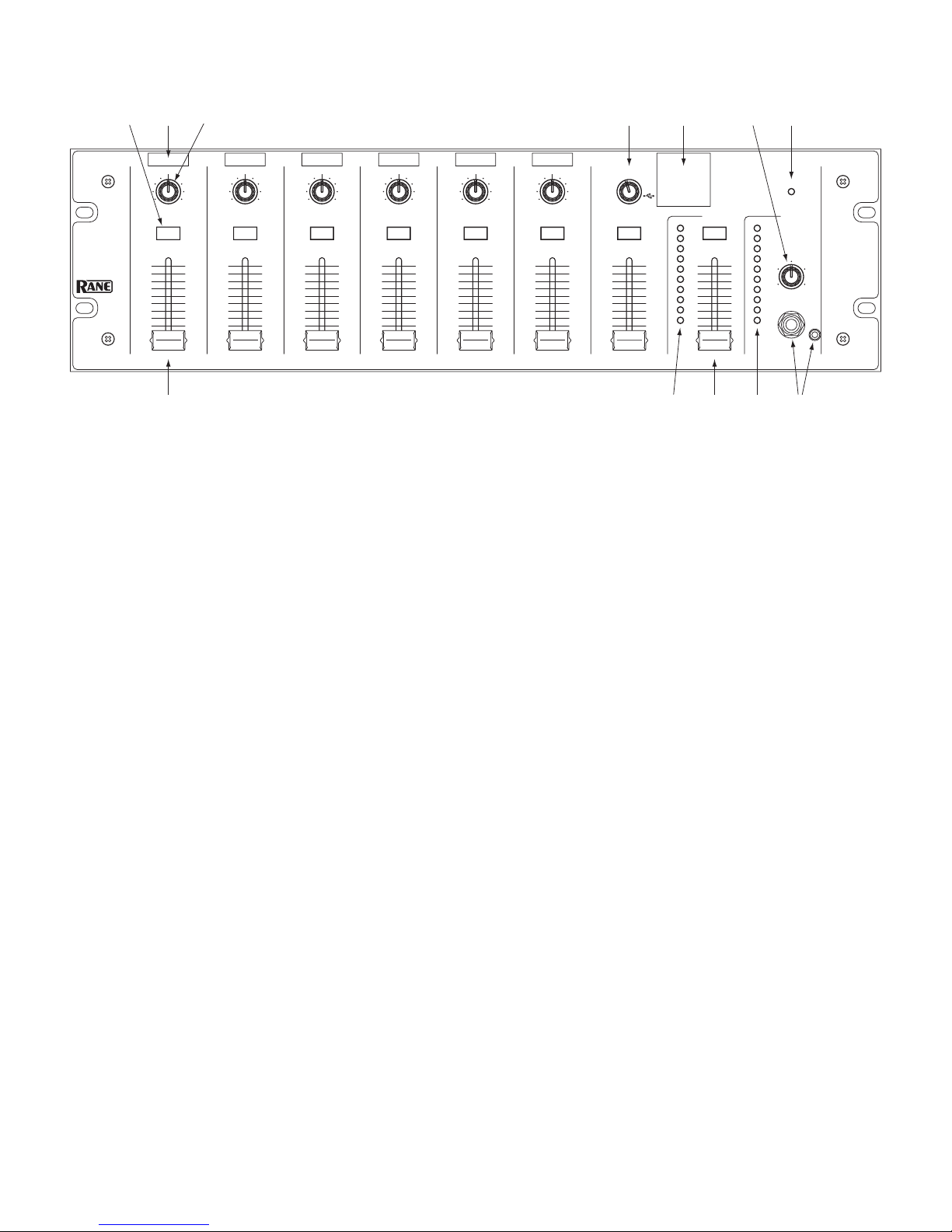
MONO MICROPHONE/LINE LEVEL INPUTS 1-6
e rear-panel MIC INPUT GAIN adjusts the input gain before
the front panel PAN and LEVEL controls. When an Input’s
MIC/LINE button is in the “out” position (MIC level), the gain
range is 12 to 60 dB. When this button is in the “in” position
(LINE-level), the gain range is -4 to 12 dB. To adjust, input
some “loud” source material. en using a screwdriver, adjust
the GAIN for each Input so the rear panel OL LED illuminates
only occasionally during extreme peaks.
Some microphones (usually called condenser mics) require
phantom power to operate. Push the PHANTOM POWER but-
ton (when needed) for each Input. If the MIC/LINE button is
engaged (LINE-level), Phantom Power is automatically defeated
for that Input. e PHANTOM POWER button activates 12
volts which is sucient power for all but the most esoteric con-
denser mics. If in doubt, check the manufacturer’s mic specs.
Pan each Input to the desired stereo image using the PAN
knobs. e 45 mm LEVEL fader on each Input can now be
adjusted to set the relative levels of each input in the main mix.
STEREO AUX INPUTS 1-5
e Stereo Source Selector and Level Fader control which stereo
source is included in the Main Mix, and at what level.
AUX 1 includes a 3.5 mm stereo TRS jack. Only connect to
one AUX 1 input (RCA or TRS) at a time.
AUX 4 includes an RIAA lter when PHONO is selected
using the LINE/PHONO switch. When connecting a phono-
graph, connect its ground wire to the ground lug above the Aux
4 input.
Each rear panel Aux Input level control adjusts the gain of
the AUX source device before it reaches the front panel Stereo se-
lector switch. e Input Level controls may be used to match the
input levels of various stereo program material. Use the following
procedure to match the Aux Input levels.
1. Set the Stereo Fader LEVEL to minimum.
2. Select the Stereo CUE button.
3. Play typical program material on an AUX source.
4. Select that source using the Stereo selector.
5. Using a screwdriver, adjust the rear panel input gain for that
source until the CUE Meter hovers between 0 and +7 dB.
6. Repeat from step 3) for all connected Aux Inputs.
MIXING
e faders on the Mic 1-6 and Stereo input channels control the
level of the corresponding inputs in the mix. e Main meter
displays the peak level of the mix (pre-Main fader). A mix with
optimal dynamic range normally lights the meter from 0 to +7
dB, and only lights the red OL led during the most extreme
peaks. A peak indication 0 dB on the meter corresponds to -20
dBFS in the mix (20 dB below clipping). e stereo Main Mix is
sent to the Record Outputs, Digital Outputs and the Main Level
fader.
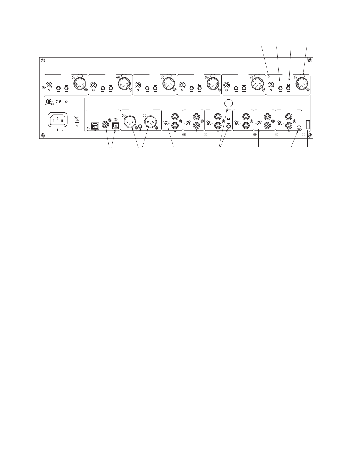
...CONNECTION, continued from page Manual-1.
RECORD OUTPUT
e analog Record Output is a line-level unbalanced output on
a stereo RCA connector. e adjacent level control adjusts the
record output level, while the front panel Main Level does not.
S/PDIF AND TOSLINK OUTPUTS
A 75 ohm cable with RCA plugs connects to the S/PDIF output
of the MLM 65. A TOSLINK (optical) cable connects to the
TOSLINK output. Both digital outputs operate at 24-bit resolu-
tion and 48 kHz sample rate.
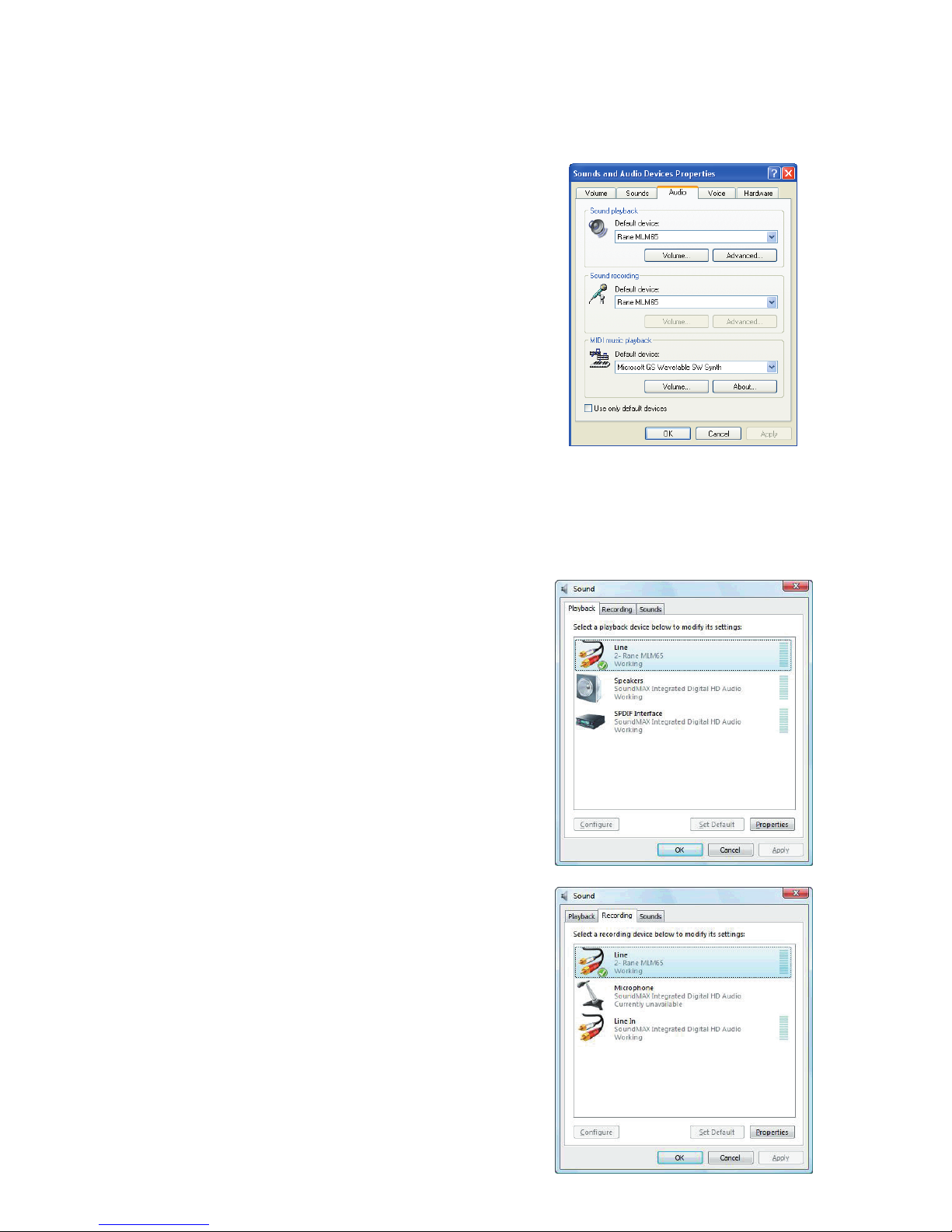
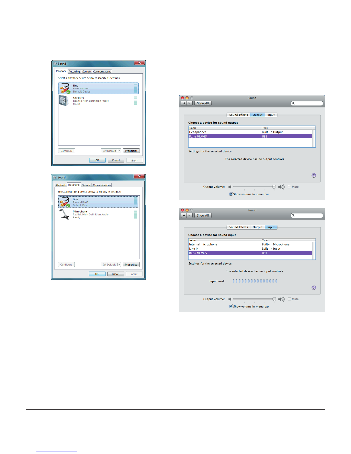
USB CONNECTION
e USB AUDIO IN / OUT port on the MLM 65 carries one
stereo channel of audio in each direction. is USB audio inter-
face is congured to use the audio device drivers that ship with
Windows and Macintosh operating systems. When the operating
system recognizes the MLM 65’s USB audio interface, the blue
LED next to the USB AUDIO jack illuminates.
USB CHARGE PORT
e USB charge port supplies up to 500 mA @ 5V to con-
nected devices, allowing them to charge their battery. e port
is congured to be recognized as a charge-only host port by the
industry’s most popular personal media players.
HEADPHONES
Shielded 1/4" and 3.5 mm TRS jacks are provided for connect-
ing headphones. We recommend only connecting one pair of
headphones at a time for best output.
e USB AUDIO IN / OUT jack provides a stereo record and
playback audio interface to a personal computer. e class-
compliant USB audio interface is supported by native drivers
on Windows and Macintosh operating systems. is USB
stereo input is available as a source for the AUX Input (see
front panel 5). e USB stereo output carries the Main
Mix unaected by the Main Level fader, and may be used to
record the Main Mix using computer software. e blue LED
next to the USB AUDIO jack illuminates when the MLM 65
is recognized by the computer.
r e IEC appliance input jack uses a C5 cord, connected to
AC mains using a line cord appropriate for your area. e
high eciency switching power supply used in the MLM
65 operates at voltages from 100 to 240 VAC, 50 or 60 Hz.
To prevent accidental shuto, there is no front panel power
switch.