Manual-4
OPERATION
The User Interface
All programming of the SRM 66 is done with the Data
wheel and the buttons on the front panel using one of the ten
programming pages. Each page consists of the page name,
multiple parameter fields and possible Command fields and
status indicators.
To navigate between pages use the Next Page (>>) and
Previous Page (<<) buttons. Within a page the Next (>) and
Previous (<) buttons move the cursor to each field.
Above each parameter field is a label indicating its
function. Once the cursor is positioned beneath the desired
parameter field the Data wheel is turned clockwise to increase
the value and counter-clockwise to decrease it. For a quick
jump to extreme values you can hold down the Shift (EXE)
Button and press either the MAX (>>) or MIN (<<) buttons.
Command Fields
Most pages contain a Command Field. Here you can Copy
settings from the current page to the clipboard, Paste settings
from the clipboard, Recall page settings from memory, and
Zero all page settings.
To access a command, position the cursor under the
Command Field, use the Data wheel to select the desired
command (not all commands are available in all pages) and
press the EXE button.
Clipboard
There are actually three separate clipboards in the
SRM 66: one for an Output’s settings (shared by all Outputs),
one for the Remote to Group settings, and one for the Output
to Group settings. Using the clipboard can greatly simplify
setting up multiple Outputs or multiple Memories. The
clipboard settings are lost whenever power is removed.
Status Indicators
Next to the page name in many pages is a Status Indicator.
In the Output pages it shows the current amount of Limiter
gain reduction or startup muting. If there is no gain reduction
being applied the field is blank. On the Memory page an
asterisk (*) appears in this field whenever the current working
Memory does not match the last recalled Memory.
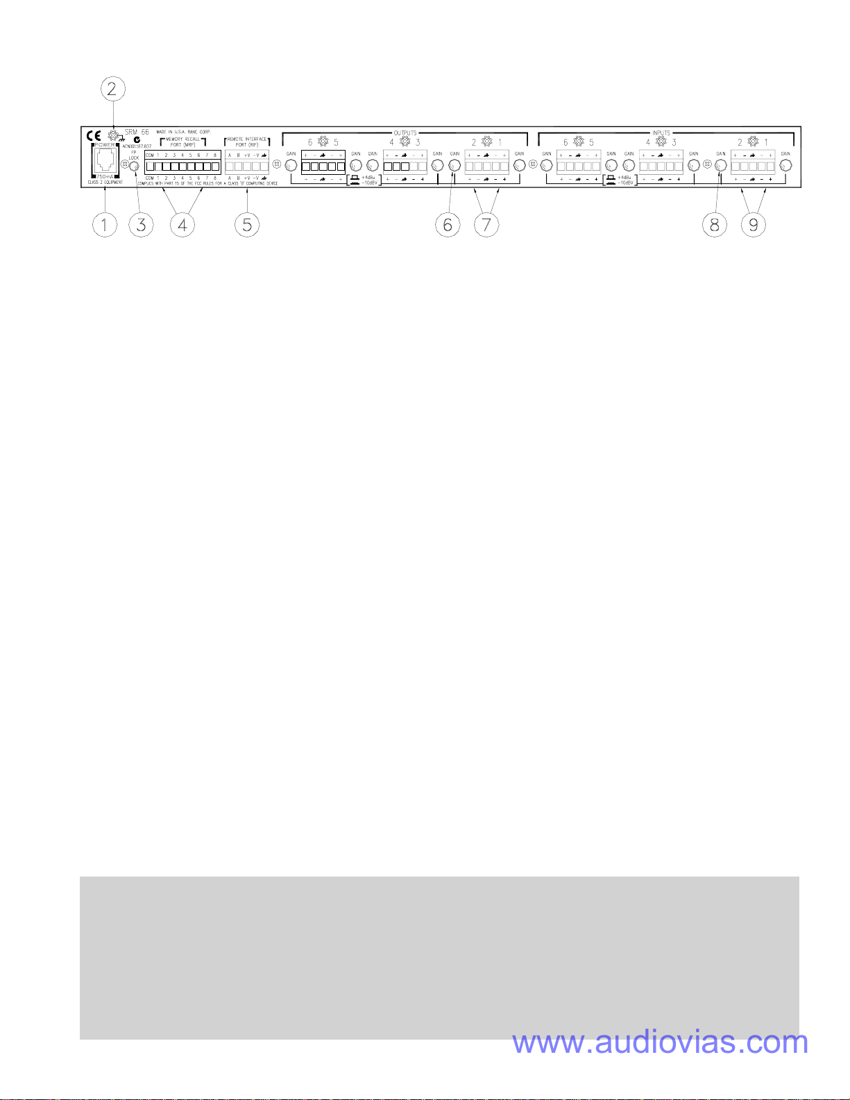
Programming the SRM 66
Programming of each SRM 66 Output requires use of only
one edit page as shown in Figure 2. Note that unique Input
mix levels are possible for each Output.
The following parameters define each Output:
IN1 Input one mix Level +6 dB to -25 dB, Off
IN2 Input two mix Level +6 dB to -25 dB, Off
IN3 Input three mix Level +6 dB to -25 dB, Off
IN4 Input four mix Level +6 dB to -25 dB, Off
IN5 Input five mix Level +6 dB to -25 dB, Off
IN6 Input six mix Level +6 dB to -25 dB, Off
MST Master mix Level +0 dB to -60 dB, Off
LIM Limit Threshold Max. to -28 dB
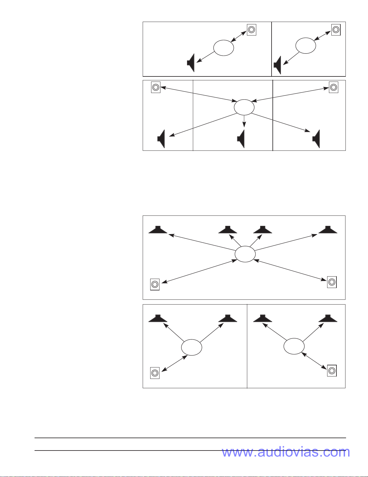
Groups
The SRM 66 uses Groups to link attenuation levels and
Limiter gain reduction of one or more Outputs. Understand-
ing and utilizing the power of them is essential to harness the
power and versatility of the unit.
The Group level parameter is independent of mix Input
level and the Output’s Master level. Group levels are not
affected by Memory changes. The Group levels Edit page is
shown in Figure 2 below.
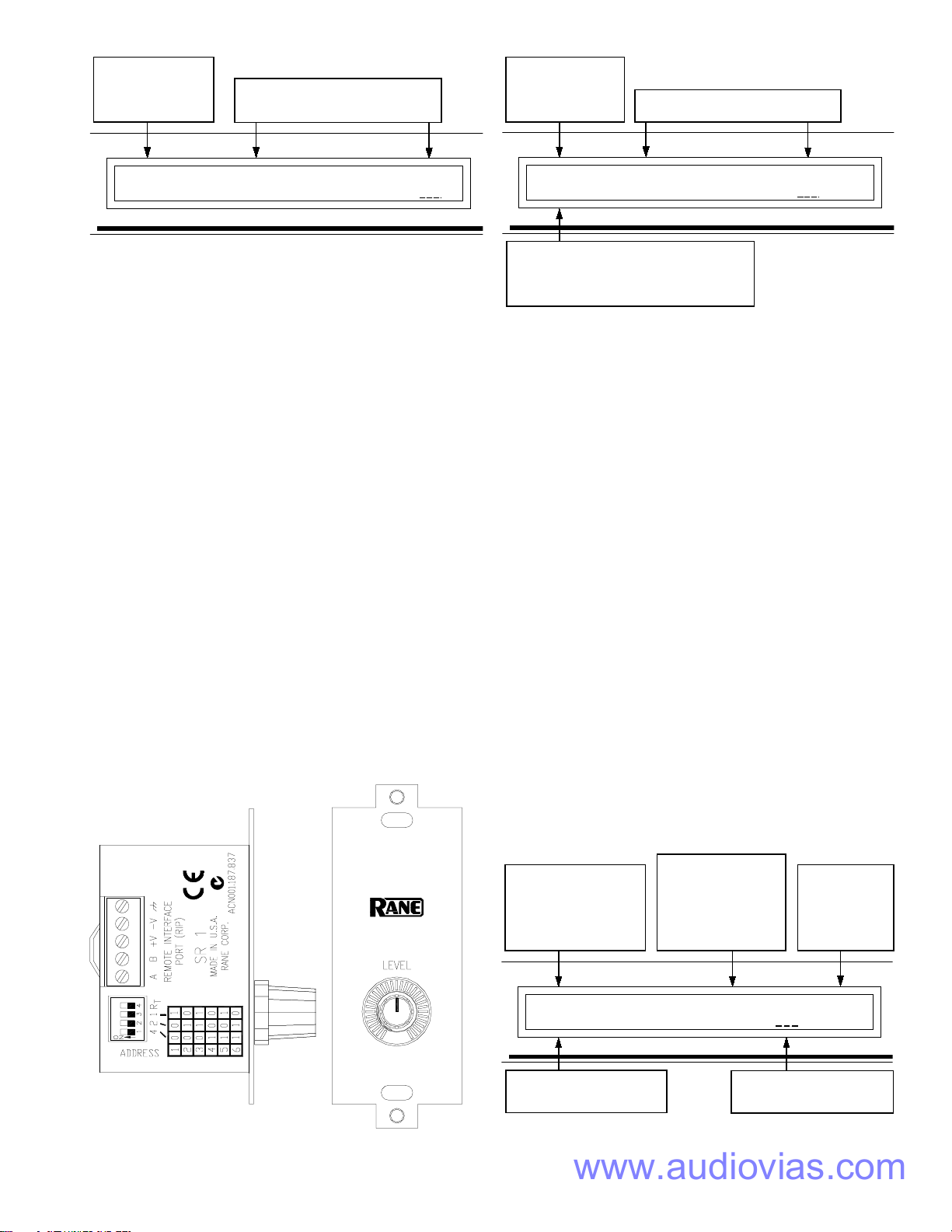
Outputs are assigned to 1 of 6 (or no/Off) Groups as
shown in Figure 3. For example, a stereo pair would typically
be assigned to the same Group. This ensures that they limit
together and are controlled by a common SR 1 Remote level
control.
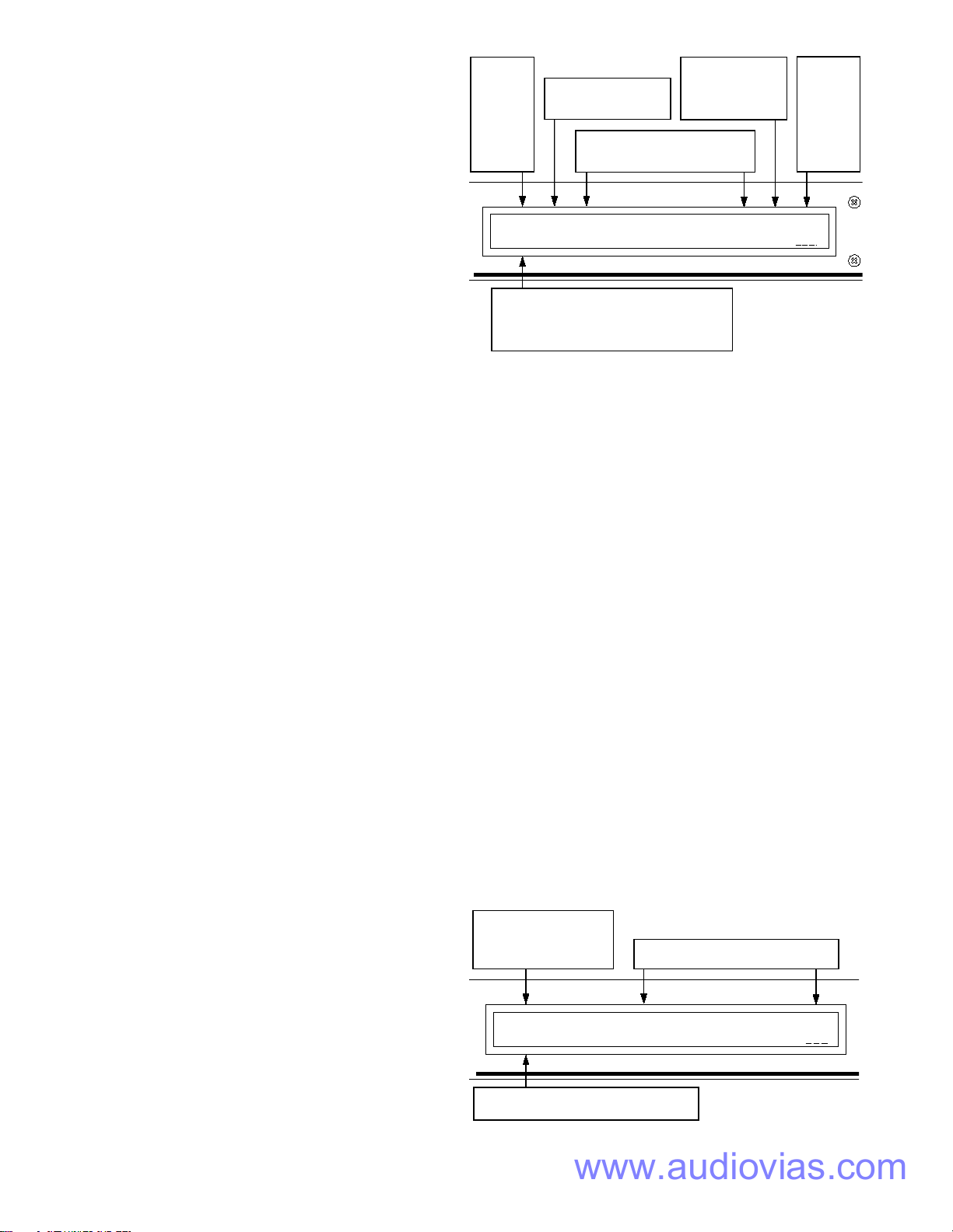
Output
Page,
where [x]
indicates
the Output
currently
being
edited.
Limiter gain reduction is
indicated in [y]dB when
the Limiter is active.
Out[x]:[y] IN1 IN2 IN3 IN4 IN5 IN6 MST LIM
Copy +6 -3 +6 0 +6 -25 0 Max
Sets the Input Level of Inputs 1-6
mixed at the Output. Range is +6
dB to -25 dB and Off.
Copy parameters of current page to clipboard.
Paste contents of clipboard to current page.
Recall[n] loads current page parameters from
Memory[n], where [n]=Memory 1-12.
Sets the Master
Level for Output[x].
Range is 0 dB to
-59 dB and Off.
Sets the
Limiter
Threshold
for Output
[x]. Range
is Max to
-28 dB.
Figure 1. Output Edit Page
Group attenuation levels
page. This has the same
action as controlling from
optional SR 1 Remote(s).
Group Lvls G1 G2 G3 G4 G5 G6
Zero All -20 -10 0 Off 0 -6
Groups G1 through G6 may be
attenuated 0 dB to -29 dB or set to Off.
When Zero All is selected, pressing EXE
sets all Group attenutation levels to 0 dB.
Figure 2. Group Levels Edit Page