Rane TTM 57SL User manual

15645
TTM 57SL
MIXER
USB
MAC WIN
Version 1.6

Introduction
Please read through these operating instructions so you will
know how to get the most from your TTM 57SL and the in-
cluded Scratch LIVE software. Keep this manual in a safe place.
If you ever lose it, a new copy may be downloaded at
www.rane.com/ttm57sl.html.
To keep up with the latest tips, and to check for software up-
dates for your TTM 57SL, visit the Official Scratch LIVE Forum
at scratchlive.net.
Minimum system requirements
• At least one turntable or CD player.
• ComputerwithUSB1portsupporting Full Speed Mode(USB 1.1).
• Screen resolution 1024 x 768 or higher.
• Hard drive space for storing music.
• PC Windows XP with Service Pack 1
Pentium 3 / 700 Mhz
256 MB RAM.
• Mac OSX 10.3
G4 / 500 Mhz
256 MB RAM.
Scratch LIVE is compatible with Intel-based Mac computers.
Note: no sound card is necessary.
Check List
ese items are included with the TTM 57SL in the box:
• Scratch LIVE software install disc.
• 2 (two) control CDs.
• 2 (two) control records.
• 1 USB cable.
• IEC C5 line cord.
• Package of 4 rubber feet.
• Quick Start Guide.
• is manual.
Copyright notices
© 2006 Rane Corporation. All rights reserved. Scratch LIVE
and the Scratch LIVE logo are trademarks of Serato Audio Re-
search. Trademarked in the U.S. and other countries. Licensed
exclusively to Rane Corporation. is software is based in part
on the work of the Independent JPEG Group, and uses libpng
code, copyright © 2000-2002 Glenn Randers-Pehrson. Win-
dows XP is either a registered trademark or a trademark of Mi-
crosoft Corporation in the United States and/or other countries.
Apple, Mac, Macintosh and iTunes are trademarks of Apple
Computer, Inc., registered in the US and/or other countries.
Important Safety Instructions
1. Read these instructions.
2. Keep these instructions.
3. Heed all warnings.
4. Follow all instructions.
5. Do not use this apparatus near water.
6. Clean only with a dry cloth.
7. Do not block any ventilation openings. Install in accordance
with manufacturer’s instructions. If rackmounting, provide
adequate ventilation. Equipment may be located above or
below this unit, but some equipment (like large power ampli-
fiers) may cause an unacceptable amount of hum or may
generate too much heat and degrade the performance of this
equipment.
8. Do not install near any heat sources such as radiators, heat
registers, stoves, or other apparatus that produce heat.
9. Do not defeat the safety purpose of the grounding-type plug.
A grounding-type plug has two blades and a third grounding
prong. e third prong is provided for your safety. If the pro-
vided plug does not fit into your outlet, consult an electrician
for replacement of the obsolete outlet.
10. Protect the power cord and plug from being walked on or
pinched particularly at plugs, convenience receptacles, and the
point where it exits from the apparatus.
11. Only use attachments and accessories specified by Rane.
12. Use only with the cart, stand, tripod, bracket, or table speci-
fied by the manufacturer, or sold with the apparatus. When
a cart is used, use caution when moving the cart/apparatus
combination to avoid injury from tip-over. is equipment may
be installed in an industry standard equipment rack. Use screws
through all mounting holes to provide the best support.
13. Unplug this apparatus during lightning storms or when
unused for long periods of time.
14. Refer all servicing to qualified service personnel. Servicing is
required when the apparatus has been damaged in any way,
such as power supply cord or plug is damaged, liquid has been
spilled or objects have fallen into the apparatus, the appara-
tus has been exposed to rain or moisture, does not operate
normally, or has been dropped.
15. e plug on the power cord is the AC mains disconnect
device and must remain readily operable.
WARNING: To reduce the risk of fire or electric shock, do not
expose this apparatus to rain or moisture. Apparatus shall not
be exposed to dripping or splashing and no objects filled with
liquids, such as vases, shall be placed on the apparatus.
RISK OF ELECTRIC SHOCK
DO NOT OPEN
CAUTION
To reduce the risk of electrical shock, do not open the unit.
No user serviceable parts inside. Refer servicing to qualified
service personnel.
e symbols shown below are internationally accepted symbols that
warn of potential hazards with electrical products.
is symbolindicates that a dangerous voltage
constituting a risk of electric shock is present
within this unit.
is symbol indicates that there are important
operating andmaintenance instructions in the
literature accompanying this unit.
WARNING

Manual-1
TTM 57SL MIXER
HARDWARE MANUAL
Contents
TTM 57SL: The Hardware ................................ 3
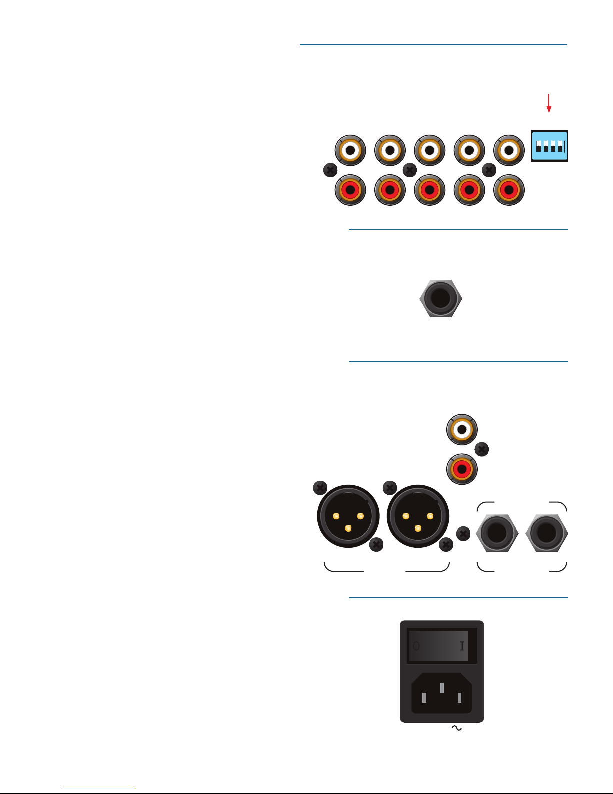
Connecting the Mixer ......................................... 3
PGM Inputs 1-4 and Aux Input......................... 3
Mic Input ......................................................... 3
Outputs ........................................................... 3
Power Supply................................................... 3
Program Controls................................................ 4
INPUT .............................................................. 4
GAIN ............................................................... 4
PAN ................................................................. 4
HIGH / MID / LOW EQ ...................................... 4
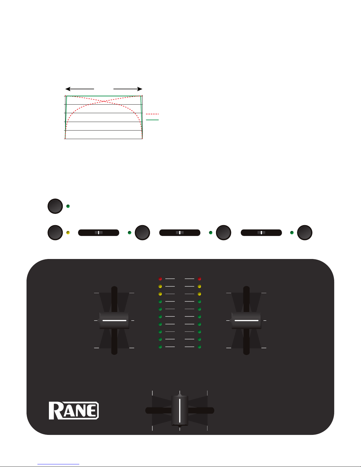
Faders.............................................................. 5
CONTOUR........................................................ 5
REVERSE ......................................................... 5
CHANNEL SWAP .............................................. 5
METER ............................................................. 5
AUX IN ............................................................ 6
MIC LEVEL and EQ........................................... 6
OUTPUT LEVELS .............................................. 6
PHONES........................................................... 6
CUE ................................................................. 6
MASTER CUE ................................................... 6
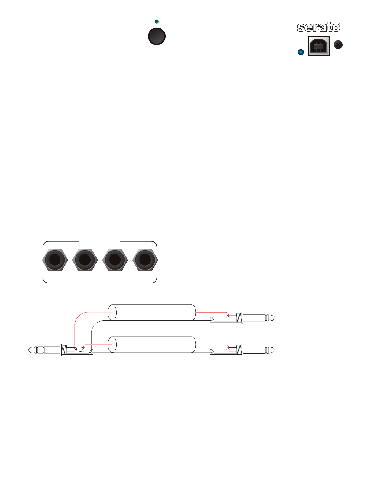
FlexFX Loop..................................................... 7
USB Streaming Audio....................................... 7
Serato and Effects Control Panel...................... 8
Internal Digital Effects..................................... 8
Inserting an Effect........................................... 8
Basic Effects Controls ...................................... 9
Footswitch....................................................... 9
Effects Cueing ................................................. 9
Control Assignments for Echo Effect...............10
Control Assignments for Filter Effect ..............10
Scratch LIVE: The Software ............................11
Install the software ........................................11
Setting up your turntables..............................12
Starting the software......................................12
Calibrating Scratch LIVE .....................................13
Audio output ..................................................13
Signal threshold .............................................13
Scope view......................................................13
Playing your first track ......................................14
Loading tracks ................................................14
Supported file types .......................................14
Using tool tips ................................................14
Playing tracks ....................................................15
The control record ..........................................15
Vinyl Scroll .....................................................15
Virtual Deck ...................................................15
Visual aids ......................................................16
Tempo Matching display .................................16
Track Overview display...................................16
Main Waveform display...................................17
Beat Matching display ....................................17
Tracking indicator ..........................................18
Autoplay.........................................................18
Master gain ....................................................18
Track gain.......................................................18
Playing tracks direct from audio CD ................18
Previewing tracks ...........................................18
33 / 45 Speeds................................................18
Repeat ............................................................18
Scratch LIVE modes ...........................................19
Absolute mode ...............................................19
Relative mode.................................................19
Censor ............................................................19
Internal mode................................................ 20
Cue points ........................................................ 21
Looping ............................................................ 21
Organizing your music...................................... 22
Grouping tracks into crates ........................... 22
Sorting your files ........................................... 22
Using the song browser ................................. 23
Searching ...................................................... 23
Prepare window ............................................ 24
Review window ............................................. 24
Editing file information ................................. 24
Status icons ................................................... 24
Display album art .......................................... 24
Recording ......................................................... 25
Keyboard shortcuts .......................................... 26
Additional setup............................................... 27
USB audio buffer size..................................... 27
Audio cache (seconds) ................................... 27
Horizontal waveforms.................................... 27
Maximum screen updates (per second) .......... 27
Instant doubles.............................................. 27
Play from first cue point ................................ 27
Play from start............................................... 27
Sort cues chronologically ............................... 27
Track end warning......................................... 27
Playback keys use shift .................................. 27
Lock playing deck.......................................... 27
Track start offset ........................................... 28
Braking.......................................................... 28
Vinyl scroll speed .......................................... 28
Drift compensation ........................................ 28
Reverse vinyl select ....................................... 28
Read iTunes™ library ..................................... 28
Auto fill overviews......................................... 28
Rescan ID3 tags ............................................. 28
Protect library ............................................... 28
Show all file types ......................................... 29
Build overviews ............................................. 29
USB dropout indicator ................................... 29
The mixer hardware control panel .................... 30
Controlling Scratch LIVE from the TTM 57SL... 30
Groups........................................................... 31
Customizing the control assignments ............ 31
Library & playback groups ............................. 32
Cueing, looping & recording groups .............. 33
Effects group: Delay & LP Filter ..................... 34
Hardware panel setup ...................................... 35
Control source ............................................... 35
Expand library on track scroll ........................ 35
Flashing deck indicator.................................. 35
Phono sensitivity ........................................... 35
Transform direction ....................................... 35
Latch kill switches ......................................... 35
Reset controls to defaults .............................. 35
Footswitch..................................................... 35
Save to mixer................................................. 35
Advanced Techniques ....................................... 36
Mixing with only one turntable ..................... 36
Swapping the turntables mid-mix .................. 36
Troubleshooting and FAQ................................. 37
Scope reading and fixes................................. 38
TTM 57SL Specifications.................................... 40
Appendix ........................................................ 41
DSP processing block diagram .......................... 41
Analog diagram................................................ 42
Foot switch diagram ......................................... 42

Manual-2
TTM 57SL Mixer Overview
e TTM 57SL Performance Mixer combines the best technolo-
gies that Rane and Serato have to offer in a single high-perfor-
mance mixer. e TTM 57SL fully integrates Rane’s proven
hardware and Serato Scratch LIVE, creating a whole new range of
possibilities for your performance. e TTM 57SL was specifically
designed to work with Scratch LIVE and the available features are
best served when used with Scratch LIVE. e TTM 57SL is also a
very competent standalone performance mixer.
Future proof
e features and functionality of your mixer will improve with
each new release of the Scratch LIVE software – and all Scratch
LIVE updates are free
Scratch LIVE control surface
Control Scratch LIVE without taking your hands off the mixer.
Navigate though your library, load tracks, hit cues, loop and
control effects via the integrated control surface. Control
includes an input for connecting a Footswitch for hands free
looping, sampling and effects.
Eects
24-bit effects using Rane and Serato's award winning studio and
live sound software technologies give you professional studio-
quality sound. e mixer is introduced with Echo and Filter
effects with more to follow.
Advanced recording capabilities
Record your mix directly to hard drive. Choose between one
single mixed output, or recording PGM 1 and 2 post-fader sepa-
rately. Perfect for editing after the mix (a mix-tape DJ’s dream!).
External sound card interface
Use the TTM 57SL as a high quality USB audio interface for your
favorite Mac or PC software — USB 1.1 with 8 channels of stream-
ing 16 bit / 44.1 kHz audio with onboard DSP effects processing.
Magnetic faders
Rane's legendary patented magnetic faders are the fastest, most
accurate, and longest lasting on the planet. e TTM 57SL uses
the same faders and performance oriented layout that made the
TTM 56 famous.
Hardware features
• Internal universal power supply works in almost any country.
• 4 line / phono switchable inputs.
• “Kills” on each EQ band, on each bus; six total.
• Dual headphone outputs: ¼" jack and 3.5mm mini-jack.
• Rane’s famous “FlexFX” effects loop system, in addition to
built-in effects.
• RCA, ¼" and XLR outputs, each with an independent vol-
ume control.
• USB 1.1 with 8 channels of streaming 16 bit / 44.1 kHz audio
• Mic input EQ and Engage switch.
TURNTABLE OUTTURNTABLE OUT
DUAL CD PLAYER OUTS
GROUND
GROUND
USB
+12-12
+12-12
10 OL
0
2
4
8
6
100
RL +6OFF
100
64
2 8
64
2 8
100
64
2 8
OL
+8
+4
+2
0
–4
–2
–8
–16
–24
PERFORMANCE MIXER
100
64
2 8
100
64
2 8
+6OFF
+6OFF
+15-15
A
D
A
D
RL
+6OFF
+6OFF
+6OFF
+15-15
MIC LOW
MIC HIGH
MIC LEVEL
OUTPUT
LEVELS
MAIN
INPUT
BOOTH
PAN
HIGH
AUX OUT
MID
GAIN GAIN
PHONES
METER
LOW
HIGH
MID
LOW
PGM 2PGM 1
TTM 57SL
A B
PGM 1 CUE PGM 2
SLOW
FADER 1 CONTOUR
FAST SLOW
FADER 2 CONTOUR
FASTSLOW
CROSSFADE CONTOUR
FAST
FlexFX
PAN
FlexFX
GROUPDECK
AUX IN
P1
2
1
INPUT
P2
2
1
J1
B1 B2
1 2
B3 B4 B5 B6
J2
CHANNEL
SWAP
MIC ON
STEREO
HOUSE
MASTER
CUE
REVERSEREVERSEREVERSE
RECORDS
CONTROL RECORD
This record contains a control signal only
and is intended solely for use in conjunction
with Serato Scratch LIVE software.
©2004Serato Audio Research
©2004Rane Corporation
Allrights reserved.
14368
10:00
CV02
12-125-33
A
RECORDS
CONTROL RECORD
This record contains a control signal only
and is intended solely for use in conjunction
with Serato Scratch LIVE software.
©2004Serato Audio Research
©2004Rane Corporation
Allrights reserved.
14368
15:00
CV02
12-125-33
B

Manual-3
AUX
PGM 1PGM 2
4321
IN
R
L
R
L
R
L
R
L
PHONO
LINE
4321
ON
MAIN BOOTH
AUX
LEFTLEFTRIGHT
BALANCED
OUT
RIGHT
MIC
BALANCED
INPUT
POWER
100-240V
50/60 Hz
20 WATTS
TTM 57SL: The Hardware
e best way to understand the TTM 57SL is to learn the basic
mixer without a computer or digital effects first. Only after you
are familiar with the ins and outs of all this mixer can do on its
own, then connect a computer and learn Scratch LIVE.
Connecting the Mixer
Leave the power unplugged until everything else is connected!
PGM Inputs 1-4 and Aux Input
e TTM 57SL has two stereo analog inputs for PGM 1 and
two stereo analog inputs for PGM 2. Any of these analog inputs
may be set for Line Input or Phono Input using the LINE /
PHONO switches located on the rear panel. Up is LINE and
down is PHONO. Unused inputs are best set to LINE. Attach
your turntable’s ground wires to the Phono Ground connectors.
Two stereo digital inputs from the USB connection, Digital 1
and Digital 2, are also available for PGM 1 and PGM 2. It is
possible to select any combination of digital and analog signals.
Any of the four analog inputs may be used for Scratch LIVE
vinyl emulation control. Input 1 or Input 2 may be selected for
Scratch LIVE Deck 1 control. Input 3 or Input 4 may be selected
for Scratch LIVE Deck 2 control. Control input sources are
selected using the Scratch LIVE software. As will be discussed
later in Program Controls, if a source has been selected for vinyl
emulation control by the Scratch LIVE software, the number is
back-lit as a reminder that the source is selected for control.
e Aux input has an independent Level control as described
on page Manual-6.
Mic Input
e Mic Input will accept either a balanced ¼" TRS (tip-ring-
sleeve) plug or an unbalanced TS (tip-sleeve) plug. Any type of
microphone may be used, except those that require phantom
power to operate. See the Mic Level section on page Manual-6.
Outputs
All analog outputs come from the same “Main Mix” signal.
Main, Booth and Aux outputs each have their own Level
controls. e Main output is on balanced XLR jacks with pin 2
“hot” per AES standards. e Booth output is on balanced ¼"
TRS (tip-ring-sleeve) jacks, though unbalanced TS (tip-sleeve)
plugs may be used. e Aux output is on regular unbalanced
RCA jacks. Because all signals are identical, users may use any
of these outputs as the “main” output if a different cable type is
required for system connection.
Rane recommends balanced wiring for the strongest signal
and rejection of hum and noise. If your cable to the amp rack
is less than 10 feet (3 meters), you can usually get away with an
unbalanced cable. See the RaneNote “Sound System Intercon-
nection” available at www.rane.com for details and cable options.
Power Supply
e TTM 57SL features an internal universal switching power
supply that operates on any AC mains 100 to 240 VAC, 50 or 60
Hz (most places in the world). All that is required when traveling
is the appropriate IEC line cord which is usually readily avail-
able. e universal supply is a major plus for the traveling DJ.
Set the unused inputs to LINE.

Manual-4
Program Controls
INPUT
Choose one of four INPUT
sources for each Program.
PGM 1 selects:
• Analog-1 (A1)
• Analog-2 (A2)
• Digital-l (D1)
• Digital-2. (D2)
PGM 2 selects:
• Analog-3 (A3)
• Analog-4 (A4)
• Digital-l (D1)
• Digital-2. (D2)
e Analog Inputs come
from your turntables or CD
players. e Digital Inputs
come from the Scratch LIVE
software “Decks” in your
laptop.
If the number for A1or A2is illuminated,
the Input has been selected by Scratch LIVE
software as the vinyl emulation input for Deck
One. If the number for A3or A4is illuminated,
the Input has been selected by Scratch LIVE as
the vinyl emulation input for Deck Two. e
backlit number is a reminder that this source may
be a control signal and not audio. You may select
a control input and use it as a normal analog input at any time
without de-selecting it for control in Scratch LIVE, but remember
that if you are playing a control record or CD, you will hear the
control signal.
See Control source and Phono sensitivity on page Manual-33.
GAIN
ese “trim” controls adjust the selected input to match other
inputs. ese controls have a built-in Limiter that prevents signal
clipping regardless of the Gain setting. If increasing the Gain
does not increase the signal level, then the signal is already at
maximum and the Limiter is controlling the signal to prevent
clipping. Turning this control down does not turn the signal off.
PAN
ese controls pan the signal between the Left and Right out-
puts.
HIGH / MID / LOW EQ
e control range is OFF to +6 dB. ese use 2nd-order, Link-
witz-Riley, Accelerated Slope™ filters. e Low-Mid crosspoint is
300 Hz. e Mid-High crosspoint is 4 kHz.
Kill switches provide instant-off for each control. e skull
lights red and the band is off when its Kill switch is pressed.
When the switch is released, the EQ goes back to the setting
of its EQ control. ese switches may be set to momentary or
toggle operation within Scratch LIVE software.
See Latch kill switches on page Manual-33.
Interactivity of the Accelerated-Slope™ EQ controls
AUDIO PRECISION AMPL (dBr) vs AMPL (dBr) 23 MAY 102 16:39:24
-40
-35
-30
-25
-20
-15
-10
-5
0
5
10
G
A
I
N
FREQUENCY
20 100 1k 10k 20
k
LOW–
MID–
HIGH–
LOW+
MID+
HIGH+
RL +6OFF
+6OFF
+6OFF
+15-15
A
D
A
D
RL
+6OFF
+6OFF
+6OFF
+15-15
INPUT
PAN
HIGH
MID
GAIN GAIN
LOW
HIGH
MID
LOW
PGM 2PGM 1
FlexFX
PAN
FlexFX
2
1
INPUT
2
1

Manual-5
Faders
Magnetic faders are used for both Channel Faders and Cross-
fader (the same faders used in the TTM 56). Each fader has an
independent Contour control and a Reverse switch.
CONTOUR
ese controls provide a full range of fader adjustment from
constant power (Slow) to extremely fast cut (Fast).
CHANNEL SWAP
is button reverses the channel assignment for all three faders.
Pressing the switch toggles Channel Swap on and off. When the
yellow indicator is lit, Channel Swap is engaged. When chan-
nels are swapped, the PGM 1 Fader controls PGM 2 and the
PGM 2 Fader controls PGM 1. PGM 1 is also moved from the
Aside of the Crossfader to the Bside of the Crossfader. Fader
Contour and Reverse controls stay with the original Fader. Fader
1 Contour and Reverse is always with the left Fader and Fader 2
Contour and Reverse is always with the right Fader. is switch
is slightly recessed to prevent accidental engagement.
METER
e Meter has two modes of operation. e METER switch
toggles between dual mono CUE and STEREO HOUSE.
When the green indicator is lit, the Meter displays Stereo Mix
output. When the green indicator is off, the Meter displays Dual
Mono Cue. e red OL indicator lights at 0 dBFS (clipping).
e Meter displays both true rms and true peak. e peak signal
indicates remaining headroom (how close to clipping) and the
rms meter shows the average signal level, which is good for
matching the perceived loudness of two signals. If the red OL
indicator lights, turn the level down using the Gain control.
OL indicators follow mode selection. If the Meter is set to
CUE, OL is independent for PGM 1 and PGM 2. If the Meter
is set to STEREO HOUSE, left and right OL are shown for the
mix.
On = Stereo House Metering
O = Dual Mono Cue Metering
0
20
40
60
80
100
Channel and CrossFader Contour
travel
dB Attenuation
SLOW
FAST
REVERSE
ese switches are provided for each fader just to the right of
each Contour control. Reverse toggles on (lit green) and off with
each push of the switch. ese switches are slightly recessed to
prevent accidental engagement.
OL
+8
+4
+2
0
–4
–2
–8
–16
–24
PERFORMANCE MIXER
METER
TTM 57SL
A B
SLOW
FADER 1 CONTOUR
FAST SLOW
FADER 2 CONTOUR
FASTSLOW
CROSSFADE CONTOUR
FAST
CHANNEL
SWAP
STEREO
HOUSE
REVERSEREVERSEREVERSE

Manual-6
+12-12
+12-12
10
OL
0
2
4
8
6
100
64
2 8
MIC LOW
MIC HIGH
MIC LEVEL
AUX IN
MIC ON
100
100
64
2 8
64
2 8
100
64
2 8
100
64
2 8
OUTPUT
LEVELS
MAIN
BOOTH
AUX OUT
PHONES
PGM 1 CUE PGM 2
MASTER
CUE
AUX IN
is level adjusts the level of the Auxiliary Input signal. is is a
full-range control providing Off to +6 dB gain adjustment.
MIC LEVEL and EQ
e MIC ON switch engages the Mic. e green indicator is lit
when the MIC is engaged.
MIC LEVEL adjusts the Mic gain over a range of Off to +50
dB. Set the gain where you want it and use the MIC ON switch
to turn the MIC on and off.
e OL indicator lights when the signal reaches clipping. If
this lights red, turn the MIC LEVEL down.
MIC HIGH and MIC LOW tone controls allow you to
adjust the bass and treble of the MIC Input signal.
OUTPUT LEVELS
Output Level controls are provided for MAIN, BOOTH and
AUX Outputs. All three outputs have the same Main Mix
source. As shown previously in Analog Outputs, the Main out-
put is a balanced output on XLR connectors, the Booth output
is a balanced signal on TRS connectors and the AUX output is
an unbalanced signal on RCA connectors. is combination of
jacks allows you to hook into other equipment regardless of the
connector type.
Headphone Cueing
e Cueing system allows users to Pan the Cue from PGM 1 to
PGM 2 or select the Master Mix. Cueing is also provided for the
internal digital effects, covered on page Manual-9.
Both 3.5 mm and ¼" jacks are provided. ese can be used
simultaneously, but using only one at a time yields more power
to the headphones.
PHONES
e headphone output can deliver very high volume to some
headphones. To avoid pain, never put headphones on your head be-
fore plugging them in. Always start with the Phones Level turned
down, and then turn it up to the desired level.
CUE
is slider allows you to pan between PGM 1 and PGM 2 in the
headphones when the Master Cue light is off. When Master Cue
is on, this control has no effect. e cue signals are post-EQ and
pre-fader.
MASTER CUE
Press this switch (green light on) to hear the Main Mix in the
headphones. When this light is off, the Cue slider takes over. HEADPHONES
(XLR)
(TRS)
(RCA)

Manual-7
FlexFX Loop
is stereo loop connects an external effects pro-
cessor. e signals coming from the PGM 1 fader,
the PGM 2 fader, or both may be routed to the
FlexFX loop. is allows a single external effects unit to process
PGM 1 and/or PGM 2.
FlexFX switches are provided for PGM 1 and PGM 2. Press-
ing the FlexFX switch lights the green indicator and sends the
signal to the external FlexFX Loop. Press the switch again and
the channel is unassigned from the loop and the green indicator
goes off.
FlexFX jacks are unbalanced mono ¼" TS (Tip/Sleeve).
SEND jacks provide output to the effects processor. RETURN
jacks provide input from the effects processor. Effects insert
devices with a single in/out TRS jack place Send on the TIP and
Return on the RING. For this application, you will need a “Y”
cable, as shown below.
Send signals may be used as another auxiliary output, allow-
ing PGM 1, PGM 2 or both to be routed to an external source
(another amp or recorder).
It is not necessary to connect cables from FlexFX Send to
FlexFX Return as the FlexFX Return jack automatically con-
nects the Send to the Return when a cable is not connected.
Any signal assigned to the FlexFX Loop will be processed by
any internal digital effect assigned to the AUX BUS. is has
the advantage of allowing one of the two internal effects to be
assigned to the AUX BUS and then assigning PGM 1 and/or
PGM 2 to the FlexFX Loop. Internal digital effects are covered
on page Manual-8.
USB
USB Streaming Audio
ere are up to eight channels of stream-
ing audio over the USB port. Two stereo
channels from the computer and two stereo
channels to the computer. While internal
processing is all 24-bit 44.1 kHz, streaming
audio is 16-bit 44.1 kHz. If the blue indica-
tor is on, the device is connected and communicating with the
computer.
Two stereo signals from the computer appear as Digital 1 and
Digital 2 inputs. ese stereo digital signals may be selected for
PGM 1 and/or PGM 2 (see source selection in Program Controls
section).
Two stereo channels are sent to the computer. ese may
be two independent stereo audio streams for recording -or- one
stereo audio stream for recording and one 4-channel stream for
vinyl emulation control. Scratch LIVE software selects the record
and vinyl emulation control sources.
When not using Scratch LIVE, the mixer appears as an 8-
channel sound card with two stereo channels in and two stereo
channels out. e source for the stereo output channels must be
selected in your software.
e following signals may be selected as the source for either
digital output to the computer:
PGM 1 Pre- or Post- Fader
PGM 2 Pre- or Post-Fader
Main Mix
AUX BUS (sum of MIC, AUX and FlexFX Return).
1-CONDUCTOR SHIELDED CABLE
T = SEND
R = RETURN
S = SHIELD
+ + SEND
RETURN
+ +
SHIELD SHIELD
SHIELD
Send/Return Cable Wiring
FlexFX
RETURN SEND
RIGHT LEFT
UNBALANCED
LEFTRIGHT
FlexFX

Manual-8
Serato and Effects Control Panel
ese “soft” controls have multiple functions for controlling
Serato Scratch LIVE software. ese also control the Internal
Digital Effects when the mixer is operated stand-alone without a
computer. Scratch LIVE controls are described on page Manual-
30.
Internal Digital Effects
ere are two Effects Processors available in the TTM 57SL.
Digital Effects hang out in the mixer instead of the software so
they are available for processing digital and analog signals even
when Scratch LIVE is not running.
• e effect for Processor 1 is the Echo.
• e effect for Processor 2 is the LFO Filter.
When Scratch LIVE is running, the deployed Effect is
indicated for each Effect Processor along with all of the control
assignments and settings. e Effects are still available when the
mixer is operating stand-alone, however, there is no display for
indicating the deployed Effect, control assignment or settings.
For this reason, you may want to begin by using the Effects
with Scratch LIVE to learn control assignments. Typically, Effects
are controlled by ear. If you know which Effect is installed in
the Effects Processors and what controls are assigned to what
functions, the Effects are very usable without the software. e
function of the controls has been standardized for stand-alone
operation to help keep stand-alone operation simple.
Inserting an Effect
ere are four possible insert points for a deployed Effect:
PGM 1, PGM 2, AUX BUS or Main Mix. An insert point can
only be used by one Effects Processor at a time. For example,
if Effects Processor 1 is inserted in PGM 1, and you insert
Effects Processor 2 in PGM 1, Processor 1 is replaced by
Processor 2. When an Effects Processor is inserted in PGM 1 or
PGM 2, pre- or post-fader operation is determined by the Effect.
For example, the Echo Effect is post-fader.
e controls required to select an Effects Processor and
determine it’s insert point are shown here:
e DECK button selects the Effects Processor to be con-
trolled. Pressing the button toggles between Effects Processor 1
and Effects Processor 2.
B1 inserts the selected Effects Processor in PGM 1.
B2 inserts the selected Effects Processor in PGM 2.
B3 inserts the selected Effects Processor in AUX BUS.
B4 inserts the selected Effects Processor in Main Mix.
Scratch LIVE software eect controls mirror the TTM 57SL front panel.
GROUPDECK
P1 P2
J1
B1 B2
1 2
B3 B4 B5 B6
J2
DECK
B1 B2
1 2
B3 B4
ECHO
PROCESSOR 1
LFO FILTER
PROCESSOR 2
PGM 1 PGM 2 AUX B MAIN
INSERT

Manual-9
Basic Effects Controls
e selected effect is edited with the remaining soft controls. e
function of some controls depends on the selected Effect. Spe-
cific control funtions are outlined in the operational details for
each Effect (see page Manual-10). e basic operation of these
controls is outlined here:
PGM 1 CUE
PGM 2 CUE
MAIN MIX CUE
CUE
PGM 1 EFFECT CUE
PGM 2 EFFECT CUE
MAIN MIX EFFECT CUE
AUX BUS EFFECT CUE
MASTER CUE
CUE PAN
ON
OFF
Eects Cue Block Diagram
B5 B6
J2
ON ON
CUE EFFECT
TRANSFORM
B5 Toggles the Effects Cue On / Off. is is a global setting and
does not change state when toggling between Effects Processors.
See the Effects Cueing section for details.
B6 toggles the selected Effects Processor On / Off.
J1 and J2 joy-switches may operate as transform switches or to
control effects parameters. J1 and J2 each feature an eight-posi-
tion joy switch, a push switch and a green mode indicator. If the
green mode indicator is off, the associated joystick operates as a
transform switch. If the green mode indicator is lit, the joystick
is assigned to an effect parameter as outlined below. Pressing the
joystick toggles between the two modes of operation. If a second
function is not available, pressing the joystick has no effect.
P1 and P2 encoders may be used to control Effect parameters.
P1 and P2 each feature a rotary encoder, a push switch and a
green mode indicator. ere are two basic modes of operation for
each of these controls:
1) e first mode of operation allows the encoder to present two
controls, with the push switch toggling between the two.
• Green mode indicator is off, the encoder adjusts parameter #1.
• Green mode indicator is on, the encoder adjusts parameter #2.
If the second parameter is not used, pushing the control does
nothing and the green mode indicator remains off.
2) e second mode of operation allows the encoder to operate
as a single rotary encoder with a Tap function. In this mode
of operation the green mode indicator is normally off and
lights only while the push switch is pressed, indicating a Tap
is being read. ere is no second rotary encoder function in
this mode.
Effects Cueing
Inserting an Effects Processor in one of the four possible insert
points automatically sends and returns audio to the appropriate
insert point, and connects the Effects Processor Cue signal to the
proper location. e Effect Cue switch is global, meaning that if
it’s on it stays on when switching between Effects Processor 1 and
Effects Processor 2. e Effect Cue is only active for the selected
Effects Processor.
To Cue an Effect before it is heard in the Main Mix, leave
the Effect off and engage the Effect Cue (B5). For an Effect Cue
to be heard in the headphones, the Effect Processor must be se-
lected, Effect Cue must be on and the Cue Pan and Master Cue
controls must be in the correct position.
e Effects Cue for an Effect inserted in PGM 1 or PGM 2
is sent to the appropriate side of the Cue Pan control, and like a
normal PGM 1 or PGM 2 Cue, is only heard if the Master Cue
switch is off. Panning between PGM 1 and PGM 2 Cue works
the same for both Effects Cue and normal Cue.
e Effects Cue for an Effect inserted in Master or Aux Bus
is only heard in the headphones if the Master Cue switch is on.
is scheme leaves Cue Pan and Master Cue features intact, even
when Cueing effects.
FOOT SWITCH
Footswitch
e last soft control is the optional footswitch. A footswitch al-
lows hands-free control of:
• Looping: in point, out point, and loop.
• Recording: start /stop record and load to either Virtual Deck.
ree buttons gives the most flexibility, but you can use
setup in the Scratch LIVE effects control panel for one- or two-
button footswitches (see page Manual-33). e foot switch needs
to be a passive pull-down device capable of grounding the TIP,
RING or TIP and RING to get the three possible states. Good
choices are the DigiTech FS300 or GNXFC. A schematic of a
3-switch foot switch is in the Appendix on page Manual-40:

Manual-10
Control Assignments for
Echo Effect
Delay Time is calibrated in BPM.
ere are two ways to set the BPM
using encoder P1. e BPM may be
set continuously over a range of 40
to 240 BPM with a resolution of 0.1
BPM by rotating P1 or simply by tap-
ping P1 to the beat.
e Regenera-
tion is adjusted
using P2.
Regeneration is
the amount of
delayed signal
fed back into
the delay input.
Regeneration
may be adjusted
continuously
transforming with the control return-
ing to the set Wet/Dry ratio when the
control is at rest (in the center).
Tip: To build an Echo in the back-
ground, leave the Effect Cue on. To
empty the Echo memory, turn Effect
Cue (B5) and Effect (B6) off.
Tip: To share
an effect with
both PGM 1
and PGM 2,
insert the effect
in the Aux Bus
and use the
FlexFX switches.
Remember that
an effect in the
Aux Bus affects
the FlexFX, Mic
and Aux Inputs.
over a range of 10% to 94% in 256 steps. ere
is no second function for P2 in the Echo Effect.
e BPM Multiplier is selected using J1.
Pressing J1 toggles between normal transform
operation and the BPM multiplier. If the green
mode indicator is lit, J1 adjusts the multiplier to
½, 1, 2, or 4.
A Wet / Dry control is provided for all effects
with J2. Pressing J2 toggles between transform
operation (indicator off ) and Wet / Dry control
(indicator on). Left joystick movement is more
Dry, right movement is more Wet. Moving the
joystick up provides instant, momentary 100%
Wet. Moving the joystick down provides instant,
momentary 100% Dry. is allows Wet or Dry
Control Assignments for
LFO Filter Effect
Filter Cutoff Frequency is adjustable
from 40 Hz to 10.24 kHz with the
primary function of P1 (green mode
indicator off ).
LFO frequency (sweep rate of
modulating signal) is calibrated in
BPM by tapping the beat on P1. e
TAP may set the BPM over a range
of 24 to 240 beats per minute with a
resolution of
0.1 BPM.
Resonance
(filter Q) is
adjusted using
the primary
function of P2
(green mode indicator off ). Resonance or (Q) is
adjustable over a range of 0.7 to 15. Resonance
determines how peaked the cutoff of the filter is.
Depth is adjusted using the second function
of P2 (green mode indicator on). e Depth is
adjustable from 0 to 4 octaves. Depth sets how
far the Filter Cutoff Frequency is moved from
the set value, at the LFO (low frequency oscilla-
tor) modulating frequency. One octave is 2x, so
if the Depth were set to 1 octave and the filter
frequency were set to 1 kHz, the filter would be
swept from a cutoff frequency of 500 Hz to 2
kHz at the LFO modulating rate.
e BPM Multiplier is selected with J1. Press-
ing J1 toggles between transform operation and
BPM multiplier. If the green mode indicator is
on, J1 may adjust the multiplier to ½, 1, 2, or 4.
Wet / Dry control is provided
for all effects on J2. Pressing J2
toggles between transform operation
(indicator off ) and Wet / Dry control
(indicator on). Left joystick movement
is more Dry, right movement is more
Wet. Moving the joystick up provides
instant momentary 100% Wet. Mov-
ing the joystick down provides instant
momentary 100% Dry. is allows
Wet or Dry
transforming
with the con-
trol returning
to the set Wet /
Dry ratio when
the control is
at rest (in the
center).
GROUPDECK
P1 P2
J1
B1 B2
1 2
B3 B4 B5 B6
J2
TRANSFORM /
BPM x1
ECHO
PROCESSOR 1
DELAY IN BPM ECHO REGENERATION
TAP BPM
LFO FILTER
PROCESSOR 2
2
4PGM 1 PGM 2 AUX B MAIN ON ON
INSERT CUE EFFECT
½
TRANSFORM /
ALL WET
MORE
DRY
ALL DRY
MORE
WET
GROUPDECK
P1 P2
J1
B1 B2
1 2
B3 B4 B5 B6
J2
TRANSFORM /
BPM x1
ECHO
PROCESSOR 1
FILTER FREQUENCY FILTER RESONANCE
FILTER DEPTHTAP / LFO BPM
LFO FILTER
PROCESSOR 2
2
4PGM 1 PGM 2 AUX B MAIN ON ON
INSERT CUE EFFECT
½
TRANSFORM /
ALL WET
MORE
DRY
ALL DRY
MORE
WET

Manual-11
The Software:
Getting started
1) Install the software
Mac
1. Insert the Software Installation CD-ROM and double-click
the installer icon.
Windows XP
1. Insert the Software Installation CD-ROM. If Setup doesn’t
start automatically, browse to the CD drive and run
setup.exe. Note: Select custom install to change the directory
you wish to install Scratch LIVE into.
2. Follow the on-screen instructions. Once the installation is
complete, Scratch Live appears in the Start Menu under All
Programs > Serato > Scratch Live.
2) Connect the TTM 57SL mixer
Mac
Mac users need only connect the mixer after installing the soft-
ware. No extra hardware installation is required.
Windows XP
ere are two drivers to install. e first is the standard Win-
dows driver that allows you to use your TTM 57SL as a sound
card. e second driver allows you to use the TTM 57SL with
Scratch LIVE.
When the TTM 57SL is connected to the computer with
the USB cable for the first time, Windows will recognize it with
'Found New Hardware' bubbles appearing in the taskbar. Wait
for it to finish as it loads the default sound card driver. When
you see the bubble "Your new hardware is installed and ready to
use," proceed to install the Scratch LIVE driver.
Installing the Scratch LIVE driver.
4. With the Scratch LIVE installation CD in the drive, run
Scratch LIVE.
5. Windows will ask you if you wish to search for drivers on the
internet – select “No, not this time”, and click “Next”
6. Choose the “Install the software automatically” option, and
click “Next”
7. Windows may warn you that the driver has not been signed.
Click “Continue Anyway”
8. Click Finish.
TTM 57SL as a sound card
e TTM 57SL will be available as a standard Windows sound
card whenever Scratch LIVE is not running. It will replace the
previous sound card and default to TTM57SL Line 2 (select D 2 on
either of the PGM INPUTS).
If you wish to change to Line 1 or back to your previous
sound card when not using the TTM 57SL:
1. Start > Control Panel > Sounds and Audio Devices.
2. Click the Audio tab.
3. Make changes using the drop menus for both Sound Playback
and Sound Recording.
4. Click OK.
Tip: Be aware that Windows system event sounds (beeps, dings,
etc.) will come through your TTM 57SL when it is your sound
card. To prevent embarrassment, have no other applications run-
ning. Better yet, turn off your computer’s sound scheme:
1. Start > Control Panel > Sounds and Audio Devices.
2. Click the Sounds tab.
3. Under Sound scheme, change to No Sounds.
4. Click OK.

Manual-12
Setting up your turntables
1. Set the tone arms to the specific recommendations of the cartridge used, such that the needle never
leaves the record, but not heavy enough that it heats up significantly. Both produce poor tracking.
2. If the track plays backwards, try swapping the left and right cables. e inputs from your turntables
might be the wrong way around. Left=white, Right=red.
3. Grounding is extremely important when using Scratch LIVE. Make sure you have good connections
from the ground wires of your turntables to the grounding post of your DJ mixer. All DJ mixers with
turntable inputs have built in grounding points for this purpose. If you do not ground your turntables
properly, the control signal will be noisy and the tracking of the record position will be erratic. (See
signal threshold on the next page.
Tip: We recommend Shure M44-7 needles for use with Scratch LIVE, due to their high output volume,
excellent tracking and low record wear.
Starting the software
Close all other programs on your Mac or PC.
When you load Scratch LIVE for the first time, you will see the following screen:
Troubleshooting: The TTM 57SL mixer is not recognized
It takes five seconds for Scratch LIVE to detect the TTM 57SL. e mixer can be unplugged at any
time; you do not need to exit Scratch LIVE before disconnecting the hardware. Use the supplied USB
cable — longer lengths are not recommended.
On some Windows machines each USB port is treated separately, so you will need to install the
driver separately for each USB port.

Manual-13
Calibrating Scratch LIVE
e TTM 57SL interprets the signal on record and communicates with the software. e signal needs to be clear for Scratch LIVE to
perform well. is section describes how to calibrate Scratch LIVE to optimize reading the control signal from your turntables or CD
players.
For best results, re-calibrate Scratch LIVE each time you move or make changes to your DJ equipment. To calibrate Scratch LIVE,
go to the setup screen by pressing the button at the top of the main screen, to the right of the Scratch LIVE logo.
Audio output
By default the output of Scratch LIVE is stereo. You can also select mono output. is setting is saved when you exit Scratch LIVE.
Signal threshold
e first step is to set signal threshold. ere is always a certain amount of background noise, particularly when using turntables in a
club environment. With a normal turntable setup, this background noise is transmitted through the body of the turntable and platter
to the stylus, and can cause stylus feedback. In Scratch LIVE, this can cause the errors on the reading of the position and velocity of
the control record.
Place the needle on the record with the record stopped. Click the estimate button to measure the background noise and esti-
mate the appropriate threshold. Moving the threshold slider to the left will make Scratch LIVE more sensitive to slow record move-
ment, but also more sensitive to background noise.
Tip: If the slider jumps to the far right, then you have a problem with noise in your turntables/CD players/mixer. Check all your
connections and make sure your equipment is well earthed. In some situations you will not be able to improve the signal quality, and
you will have to play on regardless. In this situation, stick to rel mode. (See page Manual-19 for details)
Scope view
Once you have set the threshold, start both turntables. You will see green rings appear in the scope view, as shown below.
For optimal performance the inner ring should be as close to circular as possible. Use the scope zoom slider (1x to 16x) to zoom
in or out as necessary. Use the scope L/R balance and P/A balance controls to adjust the shape of the inner ring.
e number in the top left corner of the scope view gives the current absolute position within the control record or CD. e
number in the top right corner is the current speed in RPM. In the bottom left is the current threshold setting, and the number in
the bottom right shows the percentage of readable signal – this number should be 100% when your system is calibrated properly.
Tip: If you have trouble getting the rings circular, you probably need to clean or change your needles. If the image appears as a
line, then one of the channels of the turntable is not working. See examples of potential problems and fixes on pages Manual-23-24.

Manual-14
Playing your first track
Now that you have calibrated Scratch LIVE, you are ready to play your first track. We will return to the setup screen later to set
general system preferences.
To import your own tracks, drag files and folders directly from Windows Explorer (PC version) or Finder (Mac version) into the
Scratch LIVE library.
You can also load files into Scratch LIVE by pressing the import button. Navigate the hard drive of your computer to locate your
audio files. Click on these files (or folders containing files) and drag them onto the ✽ All
…
icon.
Scratch LIVE supports importing M3U playlists.
Loading tracks
Click on the ✽ All… icon to show all the tracks in your library.
To load a track on to one of the decks, drag the track from the
track list on to either deck. You can drag the same track on to
both decks to load it onto both turntables.
Tip: Use the keyboard shortcut shift to load the highlight-
ed track on to the left deck, and shift to load the highlighted
track on to the right deck.
To start playing a track, simply put the needle on the record
and start the turntable. e track will start playing from the
position dictated by the placement of the needle on the record
– if you place the needle at the beginning of the record, the track
will start playing from the beginning. You can skip through
the track by picking up the needle and placing it further into
the record, just as with regular records (is is known as needle
dropping).
Supported file types
Scratch LIVE supports fixed and variable bit rate .MP3, Ogg
Vorbis, .AIFF, and .WAV file types. iTunes™ library and iTunes
playlists can be automatically imported in the setup screen by
clicking read iTunes library. You can also play audio direct
from CD. See Rescan 1D3 tags on page Manual-28.
Using tool tips
Click on the
?
icon to enable tool tips. Tool tips provide a handy
way to learn the various features of Scratch LIVE. Move the
mouse over a section of the screen to bring up a context-sensi-
tive tool tip. Holding the mouse over the
?
button with tool tips
turned on will show you a list of all keyboard shortcuts.
Tool tips are available in several languages. Scratch LIVE will
display the tool tips in the language that your computer is set to.
If your language is not available, the tool tips will be displayed in
English.

Manual-15
Playing tracks
When a track is loaded, the track name, artist and length
are displayed in the track title bar, and the Virtual Deck
shows a solid black line. e track will start playing as soon
as it detects the signal from the control vinyl (or CD).
The control record
e control record has two sides. e first side is 10 minutes long and contains the Vinyl Scroll
section. e second side is 15 minutes long. Scratch LIVE can be configured to work with
records playing at either 33 RPM or 45 RPM, depending on your preference.
e record has thin marks every minute, and a thicker mark every 5 minutes
(when playing at 33 RPM). ese marks are to assist you when using needle
dropping to move through the track. ese marks do not affect the play-
back of the track.
Vinyl Scroll
Vinyl Scroll allows you to select and load tracks using only your
turntables (or CD player) – no contact with the computer neces-
sary! To use Vinyl Scroll with turntables, lift the needle off the
record and drop it into special “bonus track” section at the end of
the record’s Aside. e movement of the control disk now con-
trols the selected track within your library. Lift the needle out of
the Vinyl Scroll section of the record and into the lead out (be-
tween the Vinyl Scroll area and the end of the record) to change
crates or iTunes playlists. Go back to the Vinyl Scroll area of the
record to choose a track within the crate or playlist. Once you
have found the track you wish to play, put the needle back at the
beginning of the record and it will load automatically.
is feature is available to CD users. Go to track 2on the
control CD to access Vinyl Scroll. Find the track you want to load,
and go back to track 1. e track you selected will be loaded and
ready to play.
You can reverse the direction of Vinyl Scroll and set the sensitivity
in the setup screen (page Manual-20).
Tip: You can also use Vinyl Scroll in the prepare window. See page
Manual-24.
Virtual Deck
Virtual Deck shows everything about the speed and position of a track. As the vinyl
rotates, so does the line on the label. e circular progress bar around the edge is a visual
representation of the position within the song, and can be set to flash to warn you that the track
is nearing its end. e time and remaining time are displayed in minutes and seconds. e turn-
table speed as a percentage pitch shift is shown on the left of the Virtual Deck, and the pitched
BPM (BPM with pitch adjustment multiplier added) is shown on the right of the virtual Deck. If
the track has no BPM information, pitched BPM will not be shown.
You can change the color of the record label by clicking on the Label button
to help identify records of different types. e color information is stored with the file, and is
displayed every time the song is loaded. A small icon showing the label color is displayed left of
the track information in the main library.
If you are playing regular vinyl, notice that the Virtual Deck behaves strangely as Scratch
LIVE attempts to decode the incoming signal. is will not cause any problems, but you may
find it distracting. You can unload the currently loaded track using the eject button next to each
Virtual Deck.
Tip: Use the keyboard shortcut shift-alt-arrow to unload a track from the Virtual Deck.
Eject button

Manual-16
Visual aids
When the track is playing several waveforms are displayed. Each
shows a different aspect of the track being played.
Tempo Matching display
e Tempo Matching display area provides a helpful tool for
beat matching. Scratch LIVE detects the beats within the track,
and places a row of orange peaks (for the track on the left side)
above a row of blue peaks (for the track on the right side) in the
Tempo Matching display area. When the two tracks are matched
to the same tempo, the peaks will line up.
Note that the tempo display is aligned with the beginning
of the bar, so the peaks keep their relative position as the track
plays. is display does not show the relative timing of the beats,
only the tempos of the tracks. e peaks will still line up when
the tracks are playing at the same tempo, but are out of sync.
Track Overview display
is view provides a complete overview of the waveform of the
track, and includes a marker to show the current position within
the track.
is view is useful for finding transitions within the track.
e waveform is colored according to the spectrum of the sound
– red representing low frequency bass sounds, green represent-
ing mid frequency sounds and blue representing high frequency
treble sounds.
You can jump to different positions within the track by click-
ing on the Track Overview display (disabled in abs mode).
Grey lines behind the overview show the length of the track
– a thin grey line every minute, and a thick grey line every 5
minutes.
e overview will be filled when you load the track onto a
Virtual Deck. On slower computers, you should disable auto fill
overviews in the setup screen – with this setting disabled, the
overview will be filled as you play the track.
See also: Cue points on page Manual-21
Absolute mode on page Manual-19
Build overviews on page Manual-29
Track overview display

Manual-17
Main Waveform display
is view provides a close-up view of the track, including color-
coding to show the frequency of the sound; red representing low-
frequency bass sounds, green representing mid-frequency sounds
and blue representing high-frequency treble sounds.
You can also switch to a three-band spectrum view by hold-
ing the crtl key and clicking on the waveform.
Click on the waveform to ‘scrub’ or make fine adjustments
to your position within the track. is applies to int mode only,
and may be useful if you wish to set cue points in your tracks
without your turntables or CD players connected. e Main
Waveform is zoomed around the current position in the track.
See also: Internal mode on page Manual-20.
Cue points on page Manual-21.
Tip: Use the + and – keys to zoom in and out.
In the example below, the red part of the wave represents a
kick drum, while the purple part represents a snare drum.
Kick Drum
Snare Drum
Beat Matching display
is view shows the position of beats within the track. When
beat matching, this view helps align the downbeats of the two
tracks. e markers are matched up when the two tracks are beat
matched.
Example
e following is a demonstration of using the visual aids to help
beat match. In this example, the track that is playing is on the
left deck, and the track to be mixed in is on the right deck.
1. Start the track playing on the right deck. After a few seconds,
blue peaks appear in the Tempo Matching display.
2. Adjust the pitch of the right turntable until the blue peaks
sit under the orange peaks in the Tempo Matching display.
Once they are aligned, the two tracks have the same tempo.
3. Next align the markers in the Beat Matching display. Watch
the color of the items passing by in the Main Waveform dis-
play. Remember that a kick or bass drum will be red in color,
and a snare drum will be green or blue.
is technique will by no means guarantee perfect mixes, but
may help to speed up the process of beat matching.
Main waveform display
Beat matching display
Tempo Matching display

Manual-18
Repeat
Use the repeat function to repeat the song across the
entire length of the control record.
Tip: Short “ loop” samples can be turned into a
continuous track using repeat function. e loops need
to be less than 10 seconds long, and cut at the start and
end of a bar.
Autoplay
Click the
auto
button to
enable autoplay. With this
setting turned on, when one
track finishes playing, the next
track starts automatically. Load
from a crate to play through the
songs in that crate, or from your
library to play through your
library. Use the next | and
previous | buttons to jump
to the next track or go to the
previous track in the list. Auto-
play works in both rel and int
modes. Play from start must
be checked in the setup screen
for autoplay to work correctly.
See page Manual-27.
Track gain
Use the track gain adjustment
to balance the volume of the
tracks in your library. Any ad-
justment made to the gain of a
track is saved with the file, and
will be reapplied to the entire
track when it is loaded again.
e level meter shows the
level sent to the hardware in-
terface — after both individual
track gain and master gain
adjustment.
Master gain
e master output of Scratch LIVE can be controlled using the master gain control.
is adjusts the output volume of all tracks played. Note: for best results, set the
master gain to the 12 o’clock position, and adjust the volume of individual tracks
using the track gain adjustment.
Playing tracks direct from audio CD
You can play tracks direct from an audio CD in your CD-ROM
drive. When you insert the CD into your computer, it appears
under your Scratch LIVE library. Click on the CD and the tracks
will be displayed in the track list.
Tip: Disable any third-party CD Auto-Play functions before
inserting a CD, as they may interfere with Scratch LIVE.
Previewing tracks
You can preview the tracks in your library using your computer’s
default media player. Highlight a track and press ctrl-o. is
will launch the player your computer has associated with the file
type, and start playback. Also applies to the import panel.
33 / 45 Speeds
Set this to match the speed of your turntable for normal
playback.
Tracking indicator
e tracking indicators on the main screen show the quality of
the signal coming from the control record or CD. e length
of the bar indicates the speed of the record or CD. e color
indicates the amount of position information Scratch LIVE is
receiving. When you are playing the record at normal speed, the
tracking indicator should be grey. If it is mostly red there is a
problem reading the control signal. Make sure your needles are
clean, and check the calibration in the setup screen. Note: it is
normal for the light to be red when cueing or scratching.
Other manuals for TTM 57SL
4
This manual suits for next models
2
Table of contents
Other Rane Music Mixer manuals