Rane TTM 54I User manual

Manual-1
TTM 54i
PERFORMANCE MIXER
OPERATORS MANUAL
Quick Start
For experienced turntablists, ninety percent of
the operation of the TTM 54i Performance Mixer
is obvious — however, the TTM 54i also has many
unique features. ese new features will be mastered more
quickly if you read the entire manual. Right! We know some
of you can’t resist jumping right in, so please read at least this
portion of the manual. It will help you get a good start.
• GAIN TRIM: ese controls are intended to set the signal level
before the Crossfader. Always set the GAIN TRIM controls to
indicate an average signal level of +4 on the meter with the Program
Faders set to maximum. Never use the GAIN TRIM controls to set the
output level. Always use the MASTER LEVEL control to set the output
level. is is a very simple thing, yet makes a huge difference in the performance
of your mixer.
• EFFECTS: e assignable effects loop allows insertion of a stereo effects processor into:
• Pre-Program Fader PGM 1....... Engage PGM 1 EFFECTS only.
• Pre-Program Fader PGM 2....... Engage PGM 2 EFFECTS only.
• Post-Crossfader MASTER........ Engage both PGM 1 and PGM 2 EFFECTS switches.
• Read sections and for more information.
• PHONES: e headphone output of the TTM 54i is a high power output stage (unlike most you have used before). ere are
some notable differences…
• e headphone output of the TTM 54i delivers very high volume into your headphones.
• To avoid pain, never put headphones on your head and then plug them in.
• Always start with the PHONES LEVEL turned down and then turn it up to the desired level.
• Because of the high current and low output impedance, never short one side to ground or short left and right together as is
possible with mono cup headphones. Note: Low power headphone stages typically use large resistors on their outputs, which
allow shorting, but prevent high power. e TTM 54i gives you high power but does not allow shorting.
• MIC LEVEL: For best performance, keep this control at 0 when not in use.
• For instructions on rotating Phono/Line switches to the desired location, see page Manual-6.
• Do not spray cleaner or lubricant into the front of the Program Faders or Crossfader. e fluid will just run out the bottom of
the unit. Never use unapproved cleaner or lubricants such as skateboard wheel lube, as corrosive damage may result, voiding the
warranty. See page Manual-6 for cleaning and replacement instructions and cleaner recommendations.
• Never connect anything except an RS 1 Rane AC power supply to the thing that looks like a telephone jack on the rear. is
is an 18 VAC center-tapped power unit. Consult the Rane factory for replacement or substitution.
• WEAR PARTS: is product contains the following wear parts subject to the ninety (90) day warranty period described on page
Warranty-1: FT 45 Crossfader & Channel Fader Assembly(3); ST 2 Phono/Line Switch Assembly (2).

Manual-2
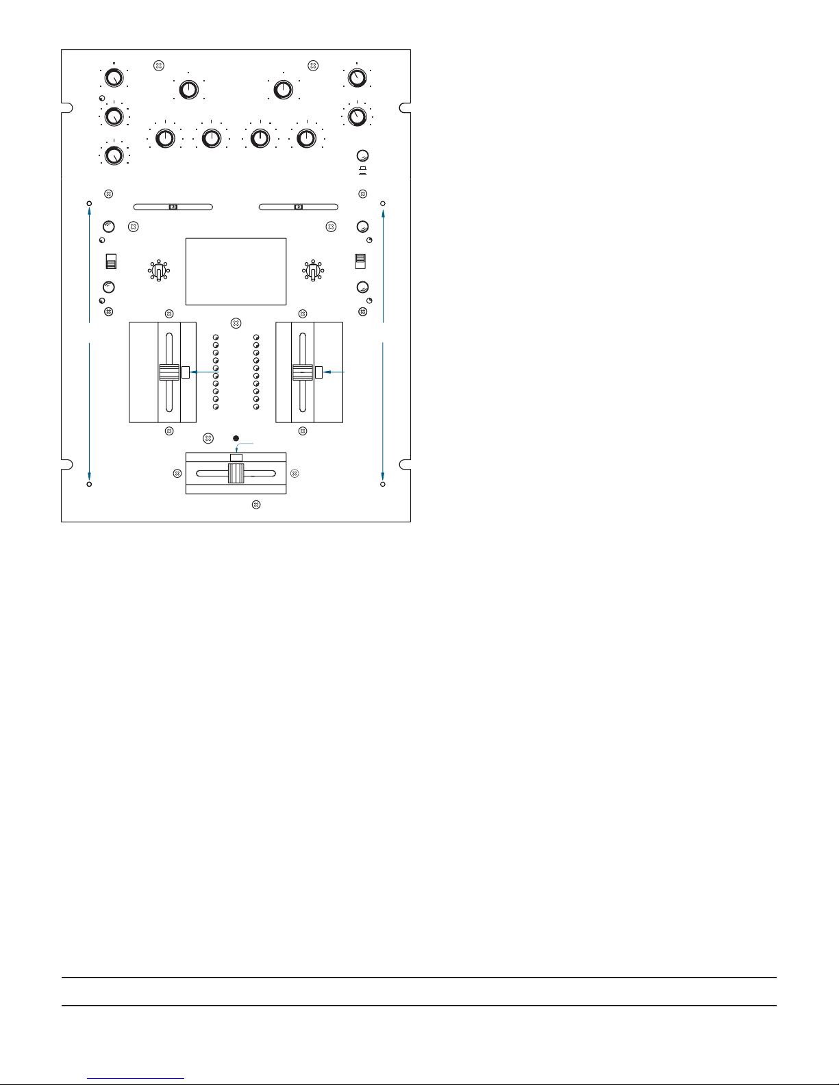
Front and Rear Panel Descriptions
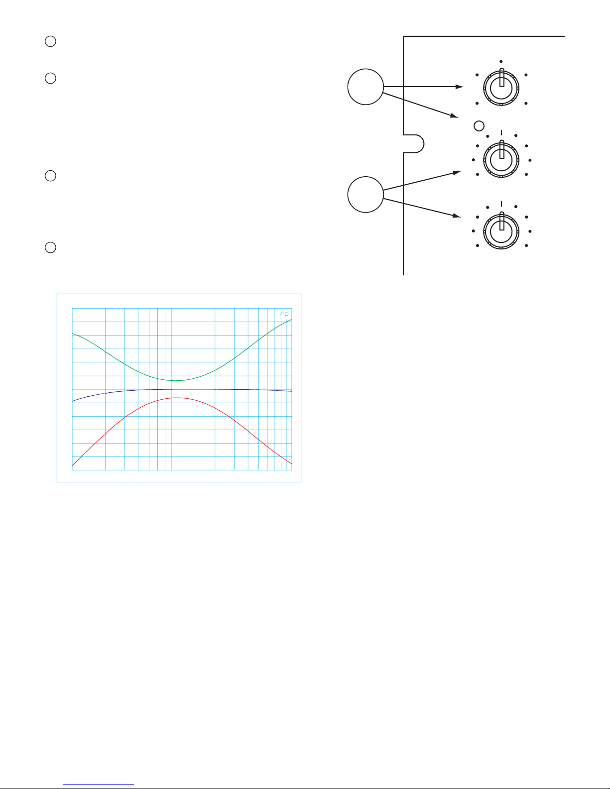
PGM 1 and PGM 2 input GAIN TRIM controls adjust the input level. With the
Program Faders () at maximum, set GAIN TRIM to give a peak reading of +4 on
the meter. Set the MASTER LEVEL () to minimum while adjusting). It is always
best to run the input level at +4 to +7. Use the MASTER LEVEL to adjust the vol-
ume at the MASTER OUT ().
BASS and TREBLE controls provide deep cut, Accelerated Slope™ EQ for PGM 1
and PGM 2. is unique EQ design makes it possible to eliminate the “sizzle” or
“bass beat” without changing the vocal range. e graph in Figure 1 indicates the
response of the filters.
BALANCE controls are used for LEFT/RIGHT balance of PGM 1 and PGM 2 or
for LEFT/RIGHT Pan effect. Push the control to the left and sound moves to the
left channel. Push the control to the right and sound moves to the right channel.
EFFECTS engage switches are provided for PGM 1 and PGM 2. ese two switches
determine the location of a single, assignable, stereo EFFECTS LOOP.
• PGM 1 & PGM 2 EFFECTS both out: EFFECTS is not engaged.
• PGM 1 EFFECTS switch in only: EFFECTS inserted pre-Program Fader PGM 1.
• PGM 2 EFFECTS switch in only: EFFECTS inserted pre-Program Fader PGM 2.
• PGM 1 & PGM 2 EFFECTS both in: EFFECTS inserted post-Crossfader Master.
CONTOUR switches provide three tapers for PGM 1 and PGM 2 Program Fad-
ers. e numbers 6, 20 and 30 indicate the mid-point attenuation. Settings can
provide smooth fade or cut and scratch effects. Note in Figure 2, the 6 dB setting
provides a quick on contour for cut and scratch (0% travel is with Program Fader
up). When used with the HAMSTER reversal switch, the Program Fader operates
very similar to the Crossfader, allowing the same hand motion for cut and scratch
operation. e 20 dB setting provides a normal audio taper while the 30 dB setting
provides a more rapid fade out.
HAMSTER switches reverse the operation of the adjacent PGM 1 and PGM 2
Program Faders. When engaged, signal is off with the Program Fader up, and
maximum with the Program Fader down.
PHONO / LINE source select switches are provided for PGM 1 and PGM 2. ese
are “clickless” switches suitable for “transform scratch” applications. e switches
are replaceable and may be rotated. See page Manual-6 for rotation and replacement
instructions.
Program Fader controls for PGM 1 and PGM 2 are ultra low noise, long-life,
monorail devices. e control element is completely isolated from the audio using
VCA circuits (voltage-controlled amplifier), providing the highest reliability and
performance. See page Manual-6 for cleaning and replacement.
PGM 1 and PGM 2 Meters provide true L+R Dual Mono indication of Post-
Program Fader signal levels. Ten segment resolution is provided with a one second
peak hold indication. With the Program Fader set to maximum, set the input GAIN
TRIM to indicate an average level of about +4.
Crossfader is implemented using Ranes’ VCA design. As with the Program Faders,
all audio is isolated from the control element, greatly extending the life and perfor-
mance of the control. See page Manual-6 for cleaning and replacement.
Figure 1. PGM Bass & Treble Controls
10
8
6
4
0
2
10
8
6
4
0
2
0
10
0
2
4
6
10
8
30
20
6
-8
LEFT
+8
-40 +10
RIGHT
-40
0
-8
2
4
10
+8
8
6
4
0
2
10
6
8
0
68 4
HAMSTER
42 6
2 0
8 10
0
-7
-10
-20
-2
-4
+7
+4
+2
+10
2
4
6
10
8
CUE 1
+10
LEFT
-40 +10
30
20
6
+10-40
RIGHT
0
2
4
10
6
8
2
MASTER
CUE
10
0
CUE 2
4
8
6
TREBLE
PGM 1
HAMSTER
CONTOUR
EFFECTS
BASS
PHONO
LINE
BALANCE
TREBLE
MIC
OL
LEVEL GAIN TRIM
PGM 1
GAIN TRIM
PGM 2
BASS
PGM 2
PHONES
LINE
PHONO
BALANCE
BASS TREBLE
PAN
LEVEL
HAMSTER
CONTOUR
EFFECTS
MASTER/CUE
TTM 54i PERFORMANCE MIXER
1
2
3
4
13
14
15
5
6
8
10
7
9
AUDIO PRECISION FRQ_UB vs 11 AUG 98 10:34:42
-80
-75
-70
-65
-60
-55
-50
-45
-40
-35
-30
-25
-20
-15
-10
-5
0
5
10
15
20
2-CHAN(dBr)
20 100 1k 10k 20k
FREQ(Hz)

Manual-3
CROSSFADER CONTOUR control allows adjusting the “shape” of the Crossfader response from
a gentle curve for smooth, long running fades, to the steep pitch required for top performance cut and
scratch effects shown in Figure 3.
CROSSFADER HAMSTER control allows reversing the operation of the Crossfader. With the combina-
tion of ActiveFader™, CONTOUR control, and HAMSTER control, the TTM 54i provides a level of flex-
ibility and performance previously unavailable.
PHONES LEVEL control adjusts the loudness of the Headphone output signal. Always start with the
LEVEL at minimum (CCW) and increase to a comfortable level with signal present and your headphones
on. is prevents tearing them off after you plug them in with the level set too high. is Headphone
Amplifier delivers very high sound pressure levels (SPL) into most headphones. Because of the high current
and low output impedance, never short one side to ground or short left and right together as is possible
with mono cup headphones. Note: Low power headphone stages typically use large resistors on their
outputs, which allow shorting, but prevent high power. e TTM 54i gives you high power but does
not allow shorting.
MASTER / CUE switch selects the HEADPHONES monitor source:
• Use MASTER to rehearse your performance. is signal is the same as that at the MASTER OUT, but is
not affected by the MASTER LEVEL control.
• Use CUE to monitor the Program Input signal, so you can “Cue” a signal before fading it in. is signal is
not affected by the Program Faders or Crossfader.
PHONES PAN control is only active when CUE is selected. is control allows you to PAN between
PGM 1 or PGM 2.
HEADPHONES jack provides a high current output, capable of driving headphones between 8 Ω and
600 Ω. Because the amplifier is capable of high current drive, it is important that the outputs are not
shorted together or to ground. Do NOT use single cup phones that short tip and ring.
MASTER LEVEL adjusts the MASTER OUTPUT level for both the balanced and unbalanced outputs.
Figure 3. Crossfader Contour control
Figure 2. Contour Switch
0
20
40
60
80
100
CrossFader Contour
travel
dB Attenuation
Slow limit
Fast limit
BA
0
10
20
30
40
50
60
70
80
90
100
0 10 20 30 40 50 60 70 80 90 100
% TRAVEL
dB ATTENUATION
6 dB
6 dB
20 dB
20 dB
30 dB
30 dB
10
8
6
4
0
2
10
8
6
4
0
2
0
10
0
2
4
6
10
8
30
20
6
-8
LEFT
+8
-40 +10
RIGHT
-40
0
-8
2
4
10
+8
8
6
4
0
2
10
6
8
0
68 4
HAMSTER
42 6
2 0
8 10
0
-7
-10
-20
-2
-4
+7
+4
+2
+10
2
4
6
10
8
CUE 1
+10
LEFT
-40 +10
30
20
6
+10-40
RIGHT
0
2
4
10
6
8
2
MASTER
CUE
10
0
CUE 2
4
8
6
TREBLE
PGM 1
HAMSTER
CONTOUR
EFFECTS
BASS
PHONO
LINE
BALANCE
TREBLE
MIC
OL
LEVEL GAIN TRIM
PGM 1
GAIN TRIM
PGM 2
BASS
PGM 2
PHONES
LINE
PHONO
BALANCE
BASS TREBLE
PAN
LEVEL
HAMSTER
CONTOUR
EFFECTS
MASTER/CUE
TTM 54i PERFORMANCE MIXER
1
2
3
4
13
14
15
5
6
8
10
7
9
CROSSFADER
CONTOUR
HAMSTER
CROSSFADER HEADPHONES
PWR
MASTER LEVEL
11 12 16 17

Manual-4
POWER connector. is is not a telephone jack! Connect only the Rane RS 1 power supply included with your TTM 54i.
MASTER OUT includes two sets of stereo outputs:
• e ¼" TRS jacks provide high current BALanced output, which should be used whenever driving equipment with a balanced
input or running distances greater than about 10 feet (3 meters). Due to the high drive capability and low impedance, never use a
mono ¼" Tip/Sleeve (no ring) cable in this jack; this grounds one side of the balanced output.
• Use the UNBALanced output for shorter runs, such as connecting to a recorder, looping to another mixer, or to other local signal
processing or amplifiers.
EFFECTS jacks are unbalanced mono ¼" Tip/Sleeve. is stereo loop is inserted in the signal path as in section .
• e SEND jacks provide the output to your effects processor.
• e RETURN jacks provide an input for the signal returning from your effects processor.
21 PGM 1 and PGM 2 inputs include both PHONO and LINE input.
• PHONO 1 and PHONO 2 inputs are RIAA compensated inputs with 18 dB per octave, 20 Hz rumble filters.
• LINE 1 and LINE 2 inputs are unbalanced line level inputs with a nominal sensitivity of -10 dBV.
• PHONO/LINE selection is made as described in .
• PGM 1 inputs are sent to the left side of the Crossfader. (HAMSTER switch out)
• PGM 2 inputs are sent to the right side of the Crossfader. (HAMSTER switch out)
22 PHONO GND terminals provide an independent ground connect point for two turntables. It is very important that each turn-
table have a very good ground connection to one of these terminals. e thumb screws are not captivated, so use care not to spin
them off and lose them.
Important Note
CHASSIS GROUNDING
If your system exhibits excessive hum or buzzing, there is an incompatibility in the grounding configuration between units some-
where. Here are some things to try:
1. Check that the turntable grounding wires are connected to the PHONO GND posts ( 22 ).
2. Try combinations of lifting grounds on units that are supplied with ground lift switches or links.
3. If your equipment is in a rack, verify that all chassis are tied to a good earth ground, either through the line cord grounding pin or
the rack screws to another grounded chassis, or tied to the ground screw located just above the POWER jack.
4. is unit’s outboard power supply does not ground the chassis through the line cord. Make sure that this unit is grounded either to
another chassis which is earth grounded, or directly to the grounding screw on an AC outlet cover by means of a wire connected to
a screw on the chassis with a star washer to guarantee proper contact.
Please refer to RaneNote “Sound System Interconnection” (supplied with this manual and available at our web site) for further
information on system grounding.
18
22
23
24
19 20 21
CLASS 2 EQUIPMENT UNBALBAL SEND RETURN
ACN001.187.837
MADE IN U.S.A.
RANE CORP.
R
L
R
L
U.S. PATENT PENDING
RETURN
SEND
INPUT
LINE 1
R
L
PHONO 2LINE 2
R
L
PHONO 1
MASTER OUT EFFECTS
MIC
PGM 2 PGM 1
EFFECTS
PHONO GND
TTM 54i
750mA
POWER

Manual-5
23 e MIC INPUT is a balanced input specifically designed for a
dynamic microphone.
24 MIC EFFECTS jacks are unbalanced mono ¼" Tip/Sleeve. is is
an independent Effects Loop for the mic. ere is no engage switch,
so the mic signal is always processed when you have an effects box
connected.
• e SEND jack provides the output to your effects processor.
• e RETURN jack provides an input for the signal returning from
your effects processor.
25 MIC LEVEL sets the gain of the Mic Input. e range of operation
is off to +60 dB. ere is no engage switch, so set the MIC LEVEL
to 0 when not in use. e OL indicator lights 6 dB before clipping.
Adjust the MIC LEVEL so the OL indicator flashes only when you
shout into the microphone.
26 MIC TREBLE and BASS controls provide as much as 8 dB of boost
or 8 dB of cut. Response is flat when the controls are set to the center
detent.
-8 +8
0
-8
2
4
10
+8
8
6
BASS
TREBLE
MIC
OL
LEVEL
26
25
AUDIO PRECISION MMIC_HF vs 11 AUG 98 11:09:01
-12
-10
-8
-6
-4
-2
0
2
4
6
8
10
12
AMPL(dBr)
100 1k 10k
FREQ(Hz)
Figure 4. Mic Bass & Treble Controls

Manual-6
©Rane Corporation 10802 47th Ave. W., Mukilteo WA 98275-5098 TEL 425-355-6000 FAX 425-347-7757 WEB www.rane.com
Fader Cleaning
With heavy use in harsh environments, the faders may need
lubrication. is treatment extends longevity and can make used
faders as good as new. e fader assembly must be removed from
the TTM 54i for proper cleaning. We recommend any of the
following cleaning solutions:
Caig Cailube MCL 100% spray lubricant
Caig Cailube MCL 5% spray cleaner
CRC 2-26 (www.crcindustries.com)
Order CaiLube MCL® from:
CAIG Laboratories, Inc.
12200 atcher Ct.
Poway, CA 92064
Phone 858-486-8388
Fax 858-486-8398
(www.caig.com)
CLEANING INSTRUCTIONS
A. Front panel removal
1. Disconnect the power cord.
2. Remove (3) slide fader knobs.
3. Remove (4) #4-40 front panel screws.
Faders and switches are now accessible.
B. Fader assembly removal
To remove any single fader:
1. Remove (2) 3mm screws.
2. Draw fader assembly out through hole.
3. Remove ribbon cable.
C. Fader cleaning
1. Hold the fader assembly away from the mixer.
2. Position the fader at mid-travel.
3. Spray cleaner/lubricant into both ends of the fader.
4. Move the fader over its full travel back and forth a few times.
5. Shake excess fluid from the fader assembly.
6. Wipe off excess fluid.
D. Fader assembly installation
1. Connect the ribbon cable to the fader assembly.
2. Place the fader assembly in position with the ribbon connector
to the right side or top, as shown.
3. Line up the fader screw holes with the mixer mounting holes.
4. Install (2 provided) 3mm screws. Using the wrong screw will
ruin the fader!
5. Replace the front panel and knobs.
Replacement Parts
Replacement Phono/Line switch assembly: ST 2
Replacement Fader Assembly: FT 45
Follow steps A, B and D in the Fader Cleaning instructions.
Replacement assemblies are available from your local
Rane dealer.
Figure 4. Phono/Line switch rotation or replacement
Rotating or Replacing Phono/
Line Switches
1. Remove the metal faceplace with a #2 philips screwdriver.
2. Remove the M2.5 x 6 mm screws with a #1 philips screw-
driver.
3. If replacing, remove the jumper cable from the old switch and
attach it to the new switch.
4. Rotate or install switch to desired PHONO position.
5. Reinstall the M2.5 x 6 mm screws with a #1 philips screw-
driver.
6. Replace the faceplate.
104034
+8-8
46
2
0 10
8
-40 +10
100
2
4
8
6
-40 +10
0 10
2 8
46
CUE 1 CUE 2
-8 +8
0
-40 +10
2
4
10
+10-40
8
6
MASTER
CUE
BASS
OL
LEVEL
MIC PGM 1
GAIN TRIM
BASS TREBLE
PGM 2
LEVEL
PHONES
TREBLE
GAIN TRIM
BASS TREBLE
MASTER/CUE
PAN
REPLACE FADER WITH RIBBON TO THE TOP
(4) SCREWS HOLD
FRONT PANEL
(4) SCREWS HOLD
FRONT PANEL
REPLACE
FADER WITH
RIBBON TO
THE RIGHT
REPLACE
FADER WITH
RIBBON TO
THE RIGHT
Table of contents
Other Rane Music Mixer manuals