Rankam Member's Mark GR2298906-MM-01 Owner's manual

1 | P a g e
Assembly Instructions & User’s Manual
for
Member’s Mark Outdoor Gas Griddle
Item Number: 980167856 / 980169672 / 980014462
Model Number: GR2298901-MM-02 / GR2298906-MM-01
Customer Assistance (spare/replacement parts): 1-888-837-1380
or Email: customerservice@rankam.com
THIS ASSEMBLY MANUAL CONTAINS INPORTANT SAFETY INFORMATION.
PLEASE READ AND KEEP FOR FUTURE REFERENCE.

2 | P a g e
Table of Contents
Quality Statement .................................................................................................................................. 3
Important Safety Information.............................................................................................................. 3
Before Assembly.................................................................................................................................... 3
Care & Use............................................................................................................................................3-6
Package Contents...............................................................................................................................7-8
Product Information .............................................................................................................................. 8
Components....................................................................................................................................... 9-11
Hardware................................................................................................................................................ 12
Tools....................................................................................................................................................... 12
Step 1 –Step 16............................................................................................................................... 13-20
Warning................................................................................................................................ 21-24
Danger....................................................................................................................................... 25
Troubleshooting.............................................................................................................................. 26-27
Care & Use Instructions ................................................................................................................27-32
Technical Data...................................................................................................................................... 32
Warranty Information.......................................................................................................................... 33
WARNING
1. Do not store or use gasoline or other flammable liquids or vapors in the vicinity of
this or any other appliance.
2. An LP cylinder not connected for use shall not be stored in the vicinity of this or any
other appliance.
DANGER
If you smell gas:
1. Shut off gas to the appliance.
2. Extinguish any open flame.
3. Open lid.
4. If odor continues, keep away from the appliance and immediately
call your fire department.
Failure to follow these instructions could result in fire or explosion
which could cause property damage, personal injury or death.

3 | P a g e
Quality Statement
Important Safety Information
Please read all instructions carefully before assembling this product.
Where applicable, and for your safety, assembly by an adult is strongly
recommended.
Use only vendor-supplied hardware to assemble this item. Using unauthorized
hardware could jeopardize the structural integrity of the item.
Hardware may loosen overtime. Periodically check that all connections are tight.
Follow all warnings and instructions when using the appliance.
Failure to follow these instructions and warnings could result in serious product or
personal damage.
Before Assembly
Remove all parts and hardware from the box. Place all items on a carpeted or
scratch-free work surface, as this will avoid damaging parts during assembly.
The shipping box can provide an ideal work surface if none is available.
Use the components and hardware lists below to identify, inventory and separate
each of the hardware and components included.
To avoid accidentally discarding small components or hardware, do not dispose
of any packaging or contents of the shipping carton until assembly is complete.
DO NOT USE power tools unless it is explicitly identified in this manual as
required for use during assembly. Power tools can damage the fasteners,
hardware and/or components.
Do not fully tighten all fasteners / screws until all parts are in place. Failure to
follow these instructions may cause the fasteners / screws to misalign during
assembly.
Care & Use
Use a soft, clean cloth that will not scratch the surface when cleaning.
Gloves are recommended while assembling the grill.

4 | P a g e
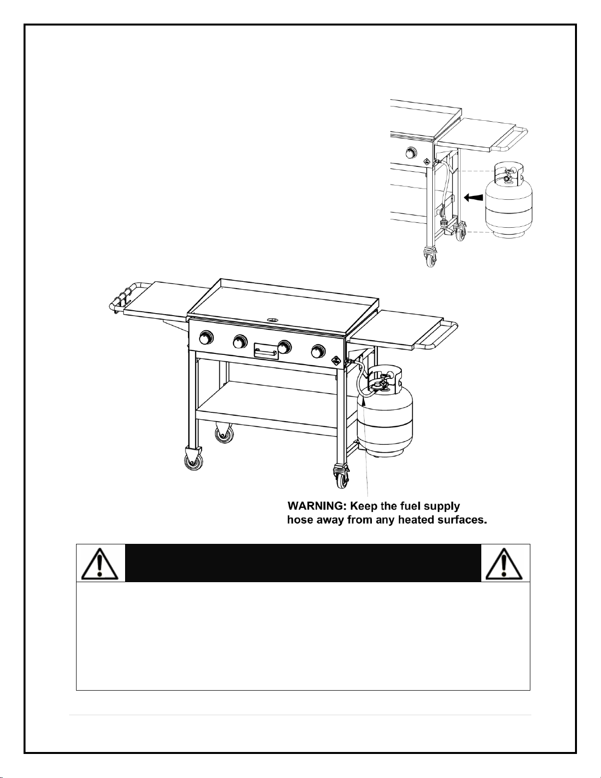
USE AND INSTALLATION OF LP GAS CYLINDER (PROPANE TANK)
BEFORE INSTALLING:
The installation must conform with local codes or (in the absence of local codes) with
either the National Fuel Gas Code, ANSI Z223.1/NFPA 54, Natural Gas and Propane
Installation Code, CSA B149.1, or Propane Storage and Handling Code, B149.2, or the
Standard for Recreational Vehicles, ANSI A 119.2/NFPA 1192, and CSA Z240 RV Series,
Recreational Vehicle Code, as applicable.
BEFORE EVERY USE:
Be sure to inspect the hose for leaks, cuts, wear, abrasion, or damage of any sort before
using this appliance. If any the hose shows any damage, it must be replaced with a new
hose specified by the manufacturer before further use.
LP GAS CYLINDER
The LP (liquid propane) cylinder specifically designed to be used with this unit MUST
have a 20 lb. (9.1kg) capacity with a Type 1 cylinder valve and an overfilling protection
device (OPD). Only use LP cylinders with this type of valve.
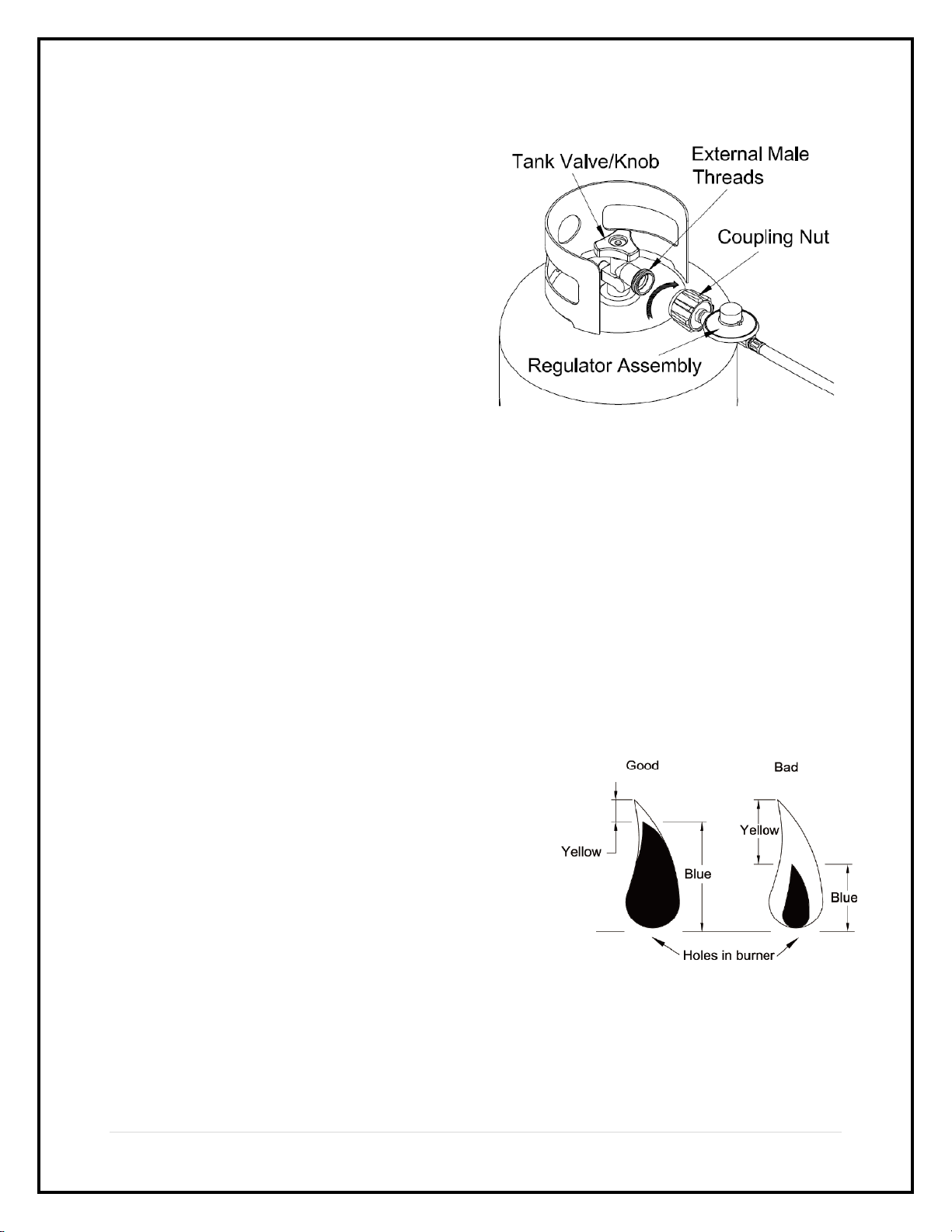
LP Tank Valve Requirements:
Purchase LP tanks only with these required measurements: 12”
(30.5cm) (diameter) x 18” (45.7cm) (tall) with 20lb. (9kg)
capacity maximum.
Type 1 outlet compatible with regulator or appliance.
Safety relief valve.
UL-listed Overfill Protection Device (OPD).
This OPD safety feature is identified by a
unique triangular hand wheel. Use only
tanks equipped with this type of valve.
LP tank must be arranged for vapor
withdrawal.
The LP cylinder must be constructed and
marked in accordance with the
Specifications for LP-Gas Cylinders of the
U.S. Department of Transportation (D.O.T.)
or the National Standard of Canada
CAN/CSA – B339, Cylinder, Spheres, Tubes
for Transportation of Dangerous Goods; and
Commission of Dangerous Goods; and Commission, as applicable.
The LP cylinder must include a collar to protect the cylinder valve.
If the outdoor cooking gas appliance is not in use, the gas must be turned off at the
supply cylinder(s).
The LP cylinder must be stored outdoors out of the reach of children and MUST NOT
be stored in a building, garage, shed, breezeway, or any other enclosed space.
Storage of an outdoor cooking gas appliance indoors is permissible ONLY if the
cylinder is disconnected and removed from the appliance.
The cylinder should ALWAYS sit in an upright position.

5 | P a g e
INSTALLING GAS CYLINDER
1. Check that the cylinder valve is closed by turning the
knob in clockwise.
2. Place cylinder into tank holder in bottom cabinet.
3. Place cylinder such that the valve opening faces the right
side table in such a way that the hose is not
kinked/damaged.
4. Attach or detach the regulator to the LP gas cylinder only
when the cylinder is placed on the cylinder holder.
CAUTION
When installing LP cylinders, the pressure regulator and hose supplied by the
manufacturer MUST be used with the appropriate cylinder. Replacement
regulators and hoses need to be specified by the manufacturer of this
appliance.
Place the dust cap on the cylinder valve outlet whenever the cylinder is not in
use. Only install the type of dust cap on the cylinder valve outlet that is
provided with the cylinder. Other types of caps or plugs may result in a propane
leak.

6 | P a g e
CONNECTION PROCEDURES
1. Make sure the tank valve is closed (turn
valve clockwise until tight).
2. Check the tank valve to ensure it has the
proper external male threads.
3. Make sure all burner valves are turned
OFF.
4. Inspect valve connections, port, and
regulator assembly. Look for any
damage or debris. Remove any debris.
Inspect the hose for damage. Never
attempt to use damaged or obstructed
equipment. Contact your local LP gas
dealer for repair.
5. When connecting the regulator assembly to the valve, hand tighten the quick
coupling nut clockwise to a complete stop. Do not use a wrench to tighten. Use of a
wrench may damage the quick coupling nut and result in a hazardous condition.
6. Open the tank valve fully (counterclockwise). Use a soapy water solution to check all
connections for leaks (leak test) before attempting to light the grill (see P.23-24). If a
leak is found, turn the tank valve off and do not use the grill until your LP gas dealer
can make repairs.
TO DISCONNECT LP CYLINDER:
1. Turn the burner valves off.
2. Turn the tank valve off fully (turn clockwise to stop).
3. Detach the regulator assembly from the tank valve by turning the quick coupling nut
counterclockwise.
FLAME CHARACTERISTICS
This procedure outlines how to check for proper
burner flame characteristics.
Burner flames should be blue and stable with little
yellow tips, with no excessive noise, or lifting. If the
flame is yellow, it indicates too much air. If any of
these conditions exist, call our customer service.
Visually check the burner flames prior to each use.
The flames should look like this picture. If not, refer
to the burner maintenance part of this manual.

7 | P a g e
Package Contents

8 | P a g e
Component
Description
Quantity
Component
Description
Quantity
1
Hook
3
12
Left Cart Beam
1
2
Side Table Handle
2
13
Right Cart Beam
1
3
Griddle
1
14
Right Rear Leg
1
4
Side Table
2
15
Locking Caster
2
5
Side Table Left
Bracket
2
16
Tank Holder
1
6
Side Table Right
Bracket
2
17
Tank Hook
1
7
Griddle Adjustor
2
18
Right Front Leg
1
8
Grease Drip Tube
1
19
Cart Base
1
9
Left Rear Leg
1
20
Front/Rear Cart Beam
2
10
Grill Body
Assembly
1
21
Tank Holder Supporting
Beam
1
11
Left Front Leg
1
22
Scraper
1
Product Information
Product Dimensions –73.3” x 26.4” x 36.7” (186.2cm x 67.1cm x 93.2cm)
Product Weight Capacity –Supports up to 110 lbs. (50 kg.)
Need Assistance? Visit us at: samsclub.com/membersmarkhelp

9 | P a g e
Components
Component 1
Hook
Part No. MET-4B0014
Qty 3
Component 2
Side Table Handle
Part No. MET-4B0015
Qty 2
Component 3
Griddle
Part No. MET-4B0016
Qty 1
Component 4
Side Table
Part No. MET-4B0017
Qty 2
Component 5
Side Table Left Bracket
Part No. MET-4B0018
Qty 2
Component 6
Side Table Right Bracket
Part No. MET-4B0019
Qty 2
Component 7
Griddle Adjustor
Part No. MET-4B0020
Qty 2
Component 8
Griddle Drip Tube
Part No. MET-4B0021
Qty 1
Component 9
Left Rear Leg
Part No. MET-4B0022
Qty 1
Component 10a
Grill Body –Body
Part No. MET-4B0023
Qty 1
Component 10b
Grill Body –Carry Over
Part No. MET-4B0024
Qty 3
Component 10c
Grill Body –Burner
Part No. GAS-4B0002
Qty 3

10 | P a g e
Component 10d
Grill Body –Valve & Manifold
Assembly
Part No. GAS-4B0003
Qty 1
Component 10e
Grill Body –Control Panel
Part No. MET-4B0025
Qty 1
Component 10f
Grill Body –Control Knob
Bezel
Part No. PLA-4B0002
Qty 4
Component 10g
Grill Body –Control Knob
Part No. PLA-4B0003
Qty 4
Component 10h
Grill Body –Ignition Burner
Part No. GAS-4B0004
Qty 1
Component 10i
Grill Body –Ignition Electrode
& Wire
Part No. ELE-4B0001
Qty 1
Component 10j
Grill Body –Hose & Regulator
Assembly
Part No. GAS-4B0005
Qty 1
Component 10k
Grill Body –Grease Cup
Part No. MET-4B0026
Qty 1
Component 11
Left Front Leg
Part No. MET-4B0027
Qty 1
Component 12
Left Cart Beam
Part No. MET-4B0028
Qty 1
Component 13
Right Cart Beam
Part No. MET-4B0029
Qty 1
Component 14
Right Rear Leg
Part No. MET-4B0030
Qty 1

11 | P a g e
Component 15
Locking Caster
Part No. HAR-4B0001
Qty 2
Component 16
Tank Holder
Part No. MET-4B0031
Qty 1
Component 17
Tank Hook
Part No. MET-4B0032
Qty 1
Component 18
Right Front Leg
Part No. MET-4B0033
Qty 1
Component 19
Cart Base
Part No. MET-4B0034
Qty 1
Component 20
Front/Rear Cart Beam
Part No. MET-4B0035
Qty 2
Component 21
Tank Holder Supporting Beam
Part No. MET-4B0036
Qty 1
Component 22
Scraper
Part No. MET-4B0037
Qty 1

12 | P a g e
Hardware
Phillips Head Bolt, M6x12mm,
Item No. A
Qty: 58
Tools
Phillips Head Screwdriver (Not included)
Adjustable Wrench (Not
included)
Symbol: The following symbols will be shown in each procedure for indication of
tightening the bolt and nut if necessary.
Need Assistance? Visit us at: samsclub.com/membersmarkhelp
Hand tighten or use the tools but
not fully tighten at this time
Tighten with tools at this time

13 | P a g e
Step 1 –Step 16
Step 1. Attach the Right Front & Rear Legs (18 & 14) to the Right Cart Beam (13)
and the Tank Holder Supporting Beam (21) using 6pcs M6x12 Bolts (A).
Remark: Please remind the holes position of the beams (13 & 21) as shown below.
Step 2. Attach the Left Front & Rear Legs (11 & 9) to the Left Cart Beam (12) using
2pcs M6x12 Bolts (A).

14 | P a g e
Step 3. Attach the left and right leg assemblies to the Front / Rear Cart Beam (20)
using 8pcs M6x12 Bolts (A).
Step 4. Attach the Cart Base (19) to the cart assembly using 12pcs M6x12 Bolts (A).

15 | P a g e
Step 5. Attach the Locking Casters (15) and tighten them to the right legs as shown.
Step 6. Make sure that all the legs, beams and cart base are aligned then fully tighten
all the bolts on the cart assembly.

16 | P a g e
Step 7. Attach the Tank Holder (16) and the Tank Hook (17) to the cart assembly using
4pcs M6x12 Bolts (A). Fully tighten the bolts.
Step 8. This step needs two people to complete! Attach the Grill Body Assembly (10)
to the cart assembly using 4pcs M6x12 Bolts (A) and fully tighten the bolts.

17 | P a g e
Step 9. Attach the Side Table Left & Right Brackets (5 & 6) to the Side Table (4)
using 4pcs M6x12 Bolts (A) as shown below. Attach the Side Table Handle (2) and
the Hooks (1) to the Side Table (4) using 2pcs M6x12 Bolts (A). Tighten all the bolts.
Step 10. Attach the left side table assembly to the grill body using 4pcs M6x12 Bolts
(A) and tighten all the bolts.

18 | P a g e
Step 11. Attach the Side Table Left & Right Brackets (5 & 6) and the Side Table
Handle (2) to the Side Table (4) using 6pcs M6x12 Bolts (A). Tighten all the bolts.
Step 12. Attach the right side table assembly to the grill body using 4pcs M6x12 Bolts
(A) and tighten all the bolts.

19 | P a g e
Step 13. Attach the Grease Drip Tube (8) to the grill body using 2pcs M6x12 Bolts (A)
and tighten all the bolts.
Step 14. Attach the Griddle Adjustor (7) to the Griddle (3) as shown.

20 | P a g e
Step 15. This step needs two people to complete! Place the griddle on the grill as
shown. You can adjust the height of griddle by rotating the griddle adjustor.
Step 16. Your unit is fully assembled! Make sure to read and follow the Instruction
Manual before operating this appliance.
Need Assistance? Visit us at: samsclub.com/membersmarkhelp
This manual suits for next models
4
Table of contents
Other Rankam Griddle manuals
Popular Griddle manuals by other brands

BIG JOHN
BIG JOHN PG-52S Owner's Manual for Assembly, Operating & Maintenance

Globe
Globe GG60TG instruction manual

APW Wyott
APW Wyott HMG-2424i Installation and operating instructions

Black Stone
Black Stone 1814 owner's manual

croydon
croydon GR1G instruction manual

Char-Broil
Char-Broil 463614023 Product guide