RAPA E Product information sheet

1
TRANSLATED FROM
MANUAL
ORIGINAL USER
REFRIGERATED COUNTERS
AND MODULES
Line E, F
08/2021
EN

Table of contents
1. Application and device code meaning 4
2. Product characteristics 5
3. Cooling system diagram 5
4. Wiring system 6
5. Wiring system diagram 6
6. Drawings 7
7. Positioning, start-up and operation 9
8. Maintenance 10
9. Transport and equipment 10
10. Temperature controller manual 11
11. Interferences 15
12. Notes 15

3
Please read this user manual carefully before using the device
and keep it for future reference.
Following the manual's recommendations guarantees long-lasting and
failure-free exploitation of the device.
IT IS FORBIDDEN
1. Make repairs on your own and fail to comply with the rules contained in
this manual regarding the connection and operation of the device;
2. Store substances that may explode in the device, such as aerosols
filled with combustible propellants;
3. Place the device in the sun;
4. Covering the inlet and outlet of air from the aggregate;
5. Switching the device on to the mains without a properly
functioning protective circuit system;
6. Use of extension cords and dividers to connect power.
7. Use devices/objects that could cause an electric spark inside
the device and in the aggregate chamber.
WARNING !
1. Incorrect connecting of the device to the mains may result in an
electric shock.
2. In the event of sparks or breakdowns, immediately disconnect the
device from the power supply by pulling the plug from the socket and
calling an authorized service technician.
3. It is necessary to protect the wiring system and control system
against water and mechanical damage.
4. When servicing and replacing parts, the device must be
disconnected from the power supply.
5. The power cord is directly connected to the sockets installed on the
device. The aggregate and lighting switches do not disconnect the
voltage in the socket.
CAUTION !
1. Before cleaning the condenser – switch the device off!
2. When cleaning the condenser, do not use tools/objects that could
cause an electric spark.
3. Water condensation on glass panes and sheets at high relative
humidity (over 60%) is a natural phenomenon. Long-term and frequent
occurrence of dewing indicates inadequate ambient conditions and is
not a basis for calling the service!
4. Take care when removing the glass panes.
Breaking the glass panes can cause injury!
The device is not intended for household use.
The device is not intended for outdoor use
.

4
1. APPLICATION AND DEVICE CODE MEANING
The device is stationary-type equipment intended for storing and expose food
products (previously cooled) at a reduced temperature. Unpacked food should be
stored (exposed) in containers or on trays specially designed for this purpose.
DEVICE CODE MEANING
Example of device code:
L-F Max/202/107/2N
L– type of the device: refrigerated counter
E, E Max, E1, E1 Max, F, F Max –device model
2N – housing made of stainless steel
202/107 – device dimensions (see table p.2)
Important information on the rating label of each device:
In the case of contact with the service
department, prepare the following data for
efficient service:
>
device type,
>
serial no. of device
Climatic class means the maximum ambient
temperature at which the device works without
disturbances.
Climatic class
3
>
maximum permissible ambient temperature
of +25°C,
>
temperature test:
ambient temperature +25°C ± 1°C
relative humidity 60% ±3%
Name, logo and device type
Device technical parameters
Manufacturer contact details

5
2. PRODUCT CHARACTERISTICS
>rated voltage: 230V~ / 50Hz
>refrigerant: HC-290; ODP = 0, GWP = 3
>working temperature: +1°C ÷ +10°C
>sound pressure level: <70dB (A)
Model
Catalogue
length/depth
[cm]
Depth with
open door
[cm]
Length of the
exposition
total/usable
[cm]
Depth of the
exposition
usable
[cm]
Length of the
storage
total/usable
[cm]
Depth of
the
storage
total/usable
[cm]
Capacity of
the exposition
usable
[l]
Capacity of
the storage
usable
[l]
Power
of
LED
lamp
[W]
Power of
LED
backlight
[W/m]
E/E1/F
202/107 183 194/190 65,5 183/179 91/80 180 270 26 4,8
180/107 183 171/167 65,5 160,5/156,5
91/80 158 236 26 4,8
153/107 164 144/140 65,5 133,5/129,5
91/80 133 195 22
4,8
138/107 164 129/125 65,5 118,5/114,5
91/80 119 173 17
4,8
123/107 159 114/110 65,5 103,5/99,5 91/80 104 150 17
4,8
80/107 173 71/67 65,5 61/57 91/80 64 86 11
4,8
E Max
E1 Max
F Max
202/107 183 194/190 65,5 77/73 1)
100/96 2)
91/80 1)
69/60 2) 180 110 1)
287 2) 26 4,8
F-NW -/107 169,5 149/145 4) 50 164/160 4) 69/60 4) 72 104 11 4,8
F-NZ -/107 93,5 3) 193/189 4) 53,5 - - 119 - 17 4,8
3. COOLING SYSTEM DIAGRAM
capillary
chemical filter
condenser
compressor
evaporator
Exposition loading limit: 1) – applicable to small storage in E Max / E1 Max / F Max
at front glass pane side – 10 cm 2) – applicable to enlarged storage in E Max / E1 Max / F Max
at evaporator side – 20 cm 3) – no storage (refrigerated counter without door)
4) – sloping storage (given dimension is maximum dimension)
Height of the low storage – 20,5 cm, enlarged storage in E Max / E1 Max / F Max – 48 cm
Usable height of the low storage – 18 cm, enlarged storage in E Max / E1 Max / F Max – 42 cm

6
4. WIRING SYSTEM
1. The device is equipped with the protective PE cable.
2. Before connecting the device to the power supply, check the compatibility of the mains
voltage with the device supplying voltage (data on the plate).
3. Connecting the device to the mains socket should be made so that the plug of the
connecting cable is visible and easily accessible for the service.
4. The device should be connected to a separate, properly made electrical circuit protected
by a fuse no greater than 10 A with a B-characteristic, ended with a socket with a protective
pin.
5. The device may be started only after confirming the effectiveness of the shock protection
with the results of measurements carried out in accordance with the applicable regulations.
6. Before carrying out any maintenance or cleaning, turn off the device with the switch and
then remove the plug from the mains socket.
7. The device is started after connecting the plug to the mains socket, and then by turning
on the switch. The backlight of the switch indicates that the device has been turned on.
8. Any repair of electrical installation and replacement of the connection cable (only into
original one available from the manufacturer) may be carried out by an authorized
electrician only.
5. WIRING SYSTEM DIAGRAM
CKO – defrost ending sensor REG – electronic temperature regulator
CRT – electronic temperature regulator sensor SPR – compressor
G– PTC heater WA – aggregate switch
GN – electric socket WO – lighting switch
MS – condenser fan MN – evaporator fan
*- additional equipment
** - applicable to refrigerated counter and module L-F/NW
STARTING CAPACITOR
RELAY
THERMAL
PROTECTION

7
6. DRAWINGS
Fig. 1
Fig. 2.
Fig. 1 Back view
Fig. 2 Side view
Fig. 3 Layout of products in enlarged storage of L-E Max, L-E1 Max i L-F Max counters.
Fig. 3
Do not block the air outlet with products.
Place the goods on the platform.
Defrost water collection drain
Aggregate cover
Aggregate switch
Lighting and backlight switch
products
depth with open door
depth
length
products
Electronic temperature controller
Enlarged storage
Standard storage

8
Fig. 4.
Fig. 4 Layout of products along the length of the exposition and storage.
It is necessary to keep the distance between the front glass pane and side of the storage.
Fig. 5 Layout of products in L-E, L-E1 counters and in small storage of L-E Max, L-E1 Max i L-F Max
counters.
Fig. 5
Fig. 6 L-E, L-E Max, L-E1, L-E1 Max – stand in front
of the glass pane and slightly open it (ca. 10°),
than hold it with both hands and lift carefully up.
Warning! In L-E, L-E Max refrigerated counters it
not allowed to leave glass pane in extremely open
position (this may damage the hinge).
Fig. 7L-F, L-F Max, L-F/NW, L-F/NZ – in order
to wash the front glass pane, it should be
gently opened using handle.
Side glass pane
Do not block the air outlet with products.
products
products
products
products
products
products
products
products

9
7. POSITIONING, START-UP AND OPERATION
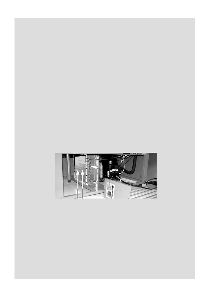
To ensure proper operation, the device should be placed in an area with a good air circulation, away
from heat sources and sunlight, free from dust (the device is not dustproof), at ambient temperature
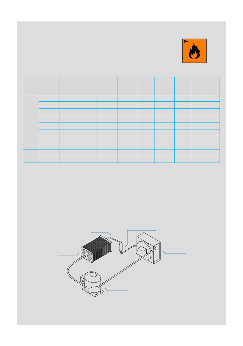
from +16°C to +25°C. It is prohibited to cover the air inlet and outlet of the aggregate. Place the
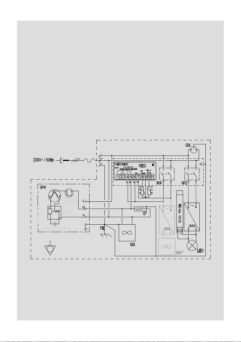
device horizontally and connect it to the power supply according to the guidelines included in the
chapter No. 4 - “Wiring system”.
The manufacturer is not responsible for interferences of the device operation in temperature below
+16°C (the defrosting cycle is too long) and over +25°C (3rd climatic class).
WARNING:
The device cannot be placed below the floor level (in a hollow).
The room in which the device is located must have a minimum cubature of 4 m3.
The sockets mounted on the device cannot be loaded with a current greater than
1.0 A (230 W) in total - regardless of the number of sockets installed and the
number of connected receivers.
Power cord is connected directly with sockets mounted on the device.
The aggregate and lighting switches do not disconnect current voltage into
the socket.
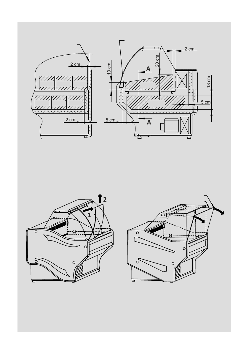
When moving the device with a set of wheels, secure the front glass against
spontaneous opening. Failure to do so may damage the front glass and may
cause a threat to people near the device.
Start-up and exploitation
The aggregate and lighting are switched on and off by means of the switches shown on Figure 1.
The temperature inside the device is adjusted by means of the electronic temperature controller,
according to the instructions included in the chapter No. 10. After switching the device on, leave it
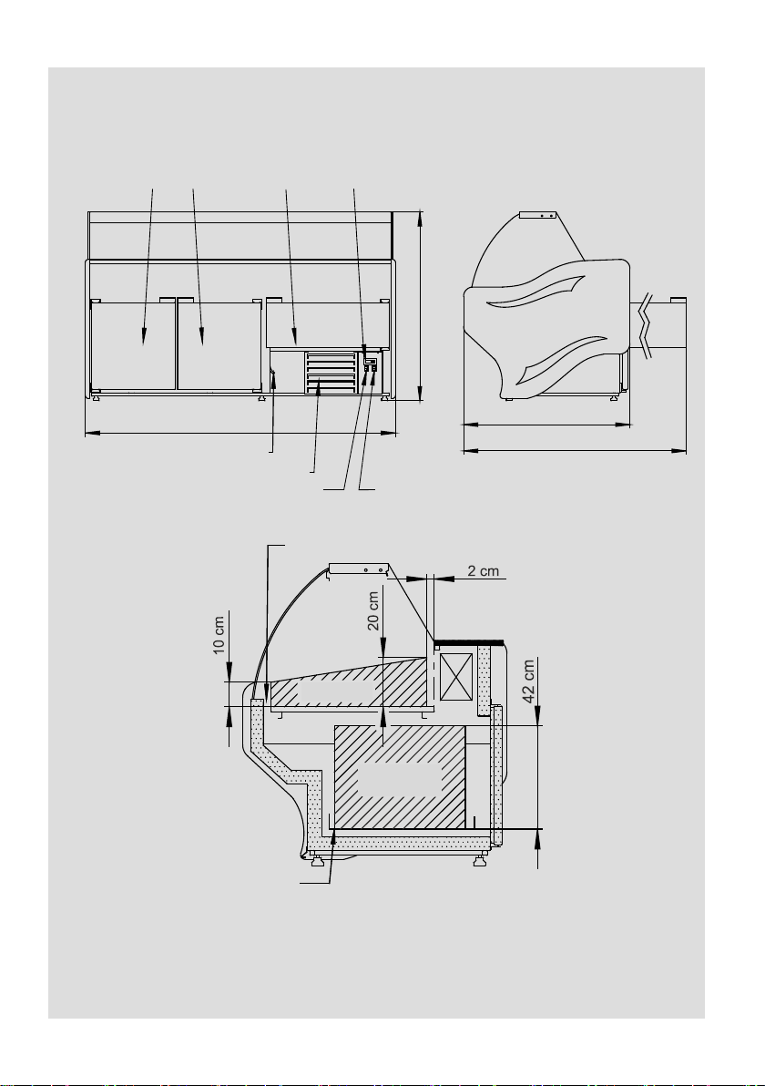
empty until its switching off for the first time. After that it is ready to be filled with products leaving
free space as on the Figures 3 and 4. The maximum glass shelf load is 10 kg (to be distributed
evenly).
In case of L-E, L-E Max refrigerated counters the maximum load, that may be on the top of front
glass panes (or cash shelves of stainless steel) is 10 kg – to be distributed evenly.
In case of L-E1, L-E1 Max refrigerated counters the maximum load, that may be on the stainless
steel top is 10 kg – to be distributed evenly.
In case of L-F, L-F Max, L-F/NW, L-F/NZ refrigerated counters the maximum load, that may be on
the glass top is 10 kg – to be distributed evenly.
In case of L-F/123 refrigerated counters it is not allowed to put the products on the top glass.
Lamp exchange - disconnect socket from LED lamp and unclip it from latches.
In case of defrost process interferences modular refrigerated counters joined in series lines, it is
recommended separation of the exposition space (in place of modules joining) by means of
partitions.
By L-F/NW module joined in series lines with L-F module sit is forbidden to open front glass panes at
the same time – it may damage the glass panes.
It is unacceptable to load the device with a warm/hot products because it causes the temperature
increase inside the device for a longer period of time and it might be the reason of a breakdown
even.

10
8. MAINTENANCE
After disconnecting the device from power supply, the general maintenance should
be done by the user, as follows:
1.washing with water of the temperature not more than +40°C with addition of natural
cleaning agents. To wash and clean the device it is forbidden to use agents
containing of chlorine and sodium of various varieties, which destroy the
protective layer and components of the device! Any residual glue or silicone on
the metal parts of the device should be removed only with gasoline (not applicable
to plastic components!). Do not use other organic solvents.
2.removing impurities from the condenser by means of vacuum cleaner
(from up to down - along the fins) at least once a month so that the flow of the
cooling air through the condenser fins is not hampered.
Not following the above instructions causes increased energy consumption,
decreased refrigeration efficiency of the device and eventually result in aggregate
overheating, which consequently may lead to failure.
While cleaning the condenser be careful not to deform the fins.
Do not wash the device with a water jet.
It is not advisable to clean the condenser with a brush as it causes impurities
penetration deep into the condenser fins and finally block the air flow
completely.
For units with an automatic condensate evaporation system, clean the container every
2 weeks to prevent the formation of unpleasant odours.
9. TRANSPORT AND EQUIPMENT
While transporting secure the device to prevent its overturning, damage of the
paint coat and breaking of the glass elements. When handling the device do not
press the glass elements, do not grab the door or aggregate protective crate to
lift the device. It is best to use belts and place them under the frame, between
the feet (so that the belts do not slide). Do not lift the device directly with a
forklift or a pallet truck without a palette, as it may damage the aggregate.
The device has to be transported in the position of its operation!
Equipment: user manual, condensate container
CLEAN THE CONDENSER WITH A VECUUM CLEANER HERE

11
10. TEMPERATURE CONTROLLER MANUAL
DISPLAY DESCRIPTION
The display is three digits with decimal point and 6 symbols (compressor, fan,
defrost, AUX, alarm and clock).
1. COMPRESSOR
The symbol is visible when the compressor operates. It flashes when the
compressor’s start up is delayed because of protective procedure. It flashes in the
cycle: two flashes – break when there is continuous operation mode activated.
2. FAN
The symbol is visible when there are evaporator fans switched on. It flashes when
the fans start-up is delayed by means of external switching off or when there
is other procedure in progress.
3. DEFROST
The symbol is visible when there is defrost function switched on. It flashes when
the defrost start-up is delayed by means of external switching off or when there is
other procedure in progress.
4. AUX
The symbol is visible when there is additional AUX output activated.
5. CLOCK
The symbol is visible when there is clock switched on – switching on by means of
„tEn” switch or when there is time limit set. When switching on the symbols
appears for few seconds as clock function availability.
6. ALARM
The symbol is visible when there is alarm activated.
SWITCHES DESCRIPTION
Information: Short pressing of any of the switches causes appearance of message
related to the currently active function.

12
7. UP / ON OFF
During normal operation of the controller; pressed for longer than 3 sec. will cause
change of controller ON/OFF operation state, pressed along with the “DOWN”
switch at the same time for longer than 3 sec. will cause activation or deactivation
of continuous operation function (after pressing there will be shown on the display
“CC” symbol). In the parameters setting mode: enable going to the next
parameters settings. During setting parameter values: it causes parameter value
increase.
8. SET / MUTE
Pressed during normal controller operation switches the alarm sound signal off;
pressed for longer than 3 sec. shows setting point; pressed along with the
“DOWN” switch at the same time while switching power supply of the controller on
will cause return to the parameters fabric settings (there will be shown “CF”
symbol on the display). In the parameters setting mode: its pressing changes the
information shown on the display: parameter name/parameter value, pressed for
longer than 3 sec. will cause saving of the set parameters. During setting
parameter values: pressed it will cause saving of the entered parameter value.
9. DOWN / DEFROST
During normal operation of the controller; pressed for longer than 3 sec. will cause
switching on/off of the manual defrost mode. In the parameters setting mode: it
allows to go to previous parameter setting. During setting parameter values: it
decreases setting value.
Set point setting (desired temperature value)
To view and modify the set point:
>press the “SET” switch for 1 sec. – the set value will start flashing;
>increase or decrease the value using the “UP” or “DOWN” switches;
>press the “SET” switch to confirm the new value
If the “SET” switch is not pressed for 60 sec., then the controller returns to
previous settings.
Manual defrost
In order to activate the manual defrost press the “DOWN” switch for more than
3 sec. The essential condition is the temperature has to be lower than +6°C.

13
Temperature checking on the defrost probe
>press the “SET” switch for longer than 3 sec. (in case there is the alarm is
activated it is necessary to switch the sound alarm off first). On the display there
will appear “PS” symbol (password);
>go to the “d/” parameter be means of the “UP” and/or “DOWN” switches, then
press the “SET” switch - there will appear temperature of defrost probe and the
symbol or
>hold the “SET” switch for longer than 3 sec. (after 60 sec. automatic return) –
return to the temperature probe indication.
Access for operator to parameters configuration and its modification
>press the „SET” switch for longer than 3 sec. (in case there is alarm activated,
switch the sound alarm first). On the display will appear the „PS” symbol (service
parameter password protected);
>go to the next parameters by means of the “UP” and/or “DOWN” switches;
>press the “SET” switch to view the current value of parameter setting;
>increase or decrease setting value by means of the “UP” and “DOWN” switches;
>press the “SET” switch to temporarily save the entered new value – it will cause
as well return to the parameters list;
>repeat the above operations – if it is necessary;
>press and hold the “SET” switch for longer than 3 sec. – it will cause parameters
saving and exit from the programming procedure.
Warning:
If no button is pressed for 60 sec., all the changes made to the parameters,
temporarily saved in the RAM, will be cancelled and the previous settings
restored.
If power is disconnected from the instrument before saving the settings (pressing
the “SET” switch for 3 sec.), all the changes made to the parameters and
temporarily saved will be lost.
Symbol Parameter Unit
Fabric
setting
min. max.
d8
Alarm bypass time after defrost
h
2
0
15
A0
Alarm and fan temperature differential
°C
2
0
20
AL
Absolute or relative temperature for
low temperature alarm
°C 2 0 150
AH
Absolute or relative temperature for
high temperature alarm
°C 8 0 150
Ad
Temperature alarm delay
min
60
0
199
High temperature alarm activation = setting + AH
High temperature alarm deactivation = setting + AH – A0
Low temperature alarm activation = setting – AL
Low temperature alarm deactivation = setting – AL + A0

14
Description of the main signals and alarms
LED flashing –The activation of the corresponding function is delayed by a timer
>awaiting an external signal or disabled by another procedure that is
already in progress. e.g. if is a continuous cycle in progress and a defrost is called,
the latter will remain pending until the end of the continuous cycle, and the
corresponding LED (defrost) will flash.
OFF flashing – state of the controller - OFF, to return to working mode (ON)
press and hold ON/OFF button for more than 3 sec.
E0 steady – control probe error (1) – active sound signal:
>probe not working: the probe signal is interrupted or short-circuited;
>probe not compatible with the instrument.
The E0 alarm signal is constant when it is the only active alarm (the temperature
value is not displayed).
E0 flashing – control probe error (1) – the alarm signal E0 is steady if it is the only
active alarm (the temperature value is not displayed), while it flashes if other alarms
are active or the second probe is displayed.
E1 flashing – evaporator probe error (2):
>probe not working, the probe signal is interrupted or short-circuited;
>probe not compatible with the instrument.
Ed flashing – The last defrost ended after exceeding the maximum duration rather
than when reaching the end defrost set point. The message disappears when the
next defrost ends correctly.
EF displayed during operation or on power-up – operating parameter reading
error (controller automatic reset). Alarm reappearance after automatic reset – it is
necessary to check the controller as there is no guarantee to keep the original
precision of the operation.
EE –data errors – In certain operating conditions, the instrument may detect errors
in the data saved. These errors may compromise the correct operation of the
instrument. If the microprocessor detects a data saving error, the display shows the
message “EE”. If the fault persists, the controller needs to be replaced. If, on the
other hand, the message disappears, it can continue to be used. When “EE” error
occurs frequently and/or remains for some time, the controller should be checked,
as the original precision may not be guaranteed.
LO flashing –low temperature alarm. The probe has measured a temperature
lower than the set point by a value that exceeds parameter AL:
>check parameters AL, Ad and A0.
The alarm is automatically reset when the temperature returns within the set limits
(see parameter AL).
HI flashing – high temperature alarm. The probe has measured a temperature
higher than the set point by a value that exceeds parameter AH.
check parameters AH, Ad and A0.

15
11. INTERFERENCES
The most often occurring interferences of the device operation:
12. NOTES
1. Attempts to repair the device on your own and not following the instructions
described in the user manual as for equipment connection and use will result
in the device malfunction.
2. The device is using natural and ecological refrigerant R-290 (propane).
Warning! In case of damage of the cooling system the refrigerator
should be immediately disconnected from the mains, any open
sources of fire located close to the unit removed and the area
carefully ventilated.
Do not use electrical appliances inside the refrigerator.
3. The manufacturer is not liable for damages resulting from the use of the device
in a manner inconsistent with the information contained in hereby user manual.
Reasons
Symptoms
Solution
Contaminated
condenser
>Visible dust layer on the condenser fins,
>
hot air coming out of the aggregate chamber,
>
loud operation of the aggregate,
>
characteristic "clicking" coming out of the
aggregate chamber every few minutes
Before cleaning of the condenser it is
necessary to switch the device off.
Impurities on the condenser should be
removed by means of vacuum cleaner
equipped with brush, gently along fins to
not to bend the lamella.
Device loaded with
warm products
>hot air coming out of the aggregate chamber,
>
loud operation of the aggregate,
>
characteristic "clicking" coming out of the
aggregate chamber every few minutes
Goods loaded in the device chamber should
be initially cooled up to maximum +4°C above
the storage temperature .
Too high ambient
temperature
>hot air coming out of the aggregate chamber,
>
loud operation of the aggregate,
>
characteristic "clicking" coming out of the
aggregate chamber every few minutes
Ambient temperature for proper operation of
the device should not exceed respectively: for
3rd climatic class +25°C.
Improper goods
distribution in
cooling chamber
>temperature on exposition is too high;
>
temperature in storage area is too low.
The goods should be placed as described in
user manual.
External source of
heat causing the
abnormal
operation of the
device
>hot air coming out of the aggregate chamber,
>
loud operation of the aggregate,
>
characteristic "clicking" coming out of the
aggregate chamber every few minutes
External source of heat might be any other
device that emits heat such as gas burner,
heater, other device equipped with a
refrigerated aggregate etc. It is necessary to
pay attention if above mentioned examples
may have influence on the deterioration of
device operation conditions.

„RAPA” S. Międlar W. i I. Szymańscy sp. j.
9 Ceramiczna Street, 20-149 Lublin, POLAND
Reg. No BDO 000009031
tel. +48 81 742 53 10 do 14
e-mail: rapa@rapa.lublin.pl
Service:
e-mail: servi[email protected]
www.rapa.pl
The package should be removed according
to the regulations of environmental protection.
The warranty card and conditions
are effective only in the area of Poland.
This manual suits for next models
5
Table of contents
Other RAPA Refrigerator manuals