2
ReassemblingtheHood..............................................................................................................................36
Foreword
Aswithanytypeoflightingretrofit,therearemanydangers,difficulties,andpitfallsthatmay
occur.TheRedSeaMax250retrofitshouldbeattemptedbypeoplefamiliarwithACpowerandwiring,
relays,electronics,LEDs,off‐LineandDC‐DCLEDDrivers,solderingLEDs,seriescircuits,andbe
comfortablewiththefactthatthisretrofitwillrequirecompletedisassemblyandremovalofsome
contentsoftheoriginalhood.Ifyouareuncomfortablewithpotentialhazards,dangers,orpitfallsthat
mayoccurinthecourseofperformingthisretrofit,youshouldnotattemptthisretrofit.Aswithall
projects,beforebeginningpleasedoublechecktoensureyouhaveallthepartsneededtocompletethe
buildandcontactusimmediatelyifanythingwasleftoutofyourorder.
Outline
Hereisageneraloutlineofassemblystepsintheorderthatworkedwellforus:
1. Removehood,removeT5bulbs,openhood,removethestockballasts,T5socketsand
bulbclips.
2. Drill4mountingholesinRSMreflectorforeachheatsink.ZiptieheatsinkstoRSM
reflector.
3. CompleteLEDwork:attachLEDstoheatsinkandthenwirethemtogether.YourLED
stringswilllikelyjumpacrosstwoheatsinks,sobeawareofthiswhenwiring.
4. InstallHLGandLDDdrivers.
5. Drillholefordimmingcontrollerwiringifnecessary.
6. CompleteWiring:WiredriverstoACpower,hookupdimmingwires,andLEDwires.
7. Testunderpower.
********ENSURETHEREISNOPOWERTOTHEDRIVERSUNTILALLWIRINGISCOMPLETE********
8. Closehoodup,re‐attachtoRSMandbaskintheshimmer.
HoodPreparation
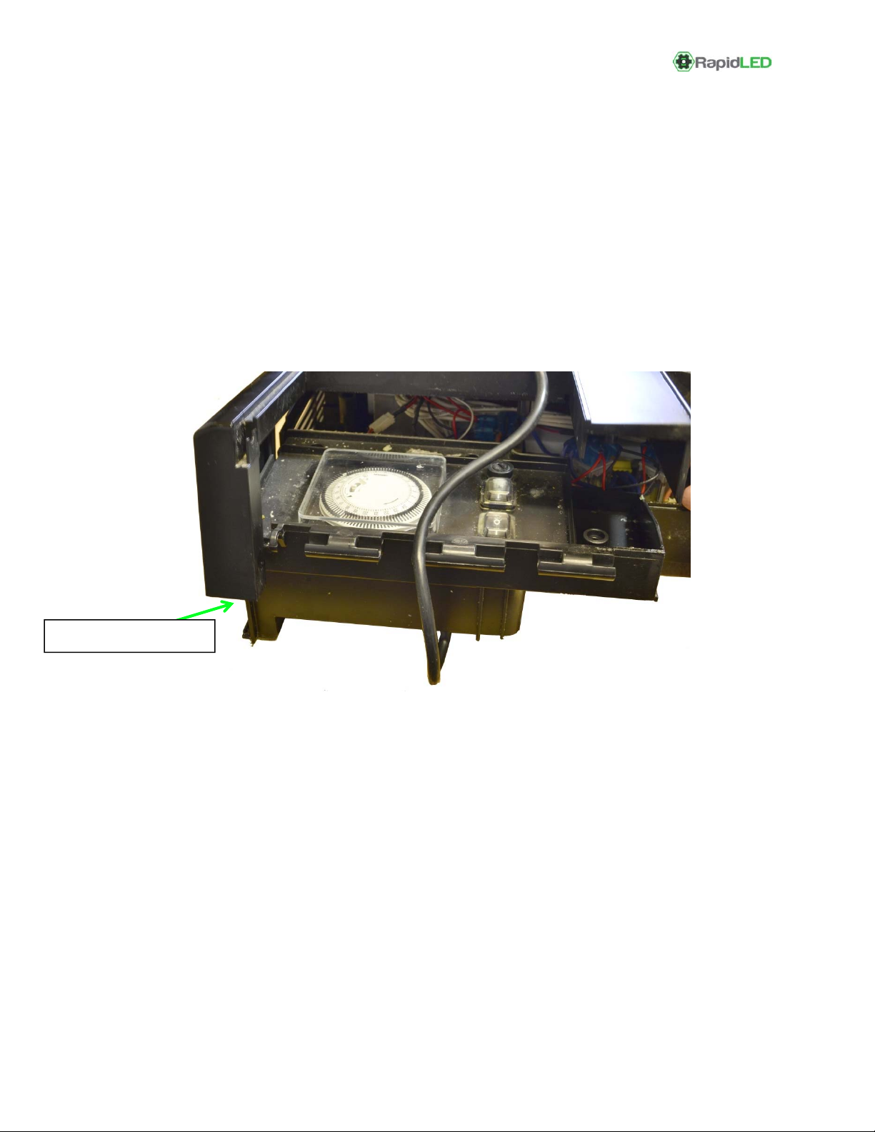
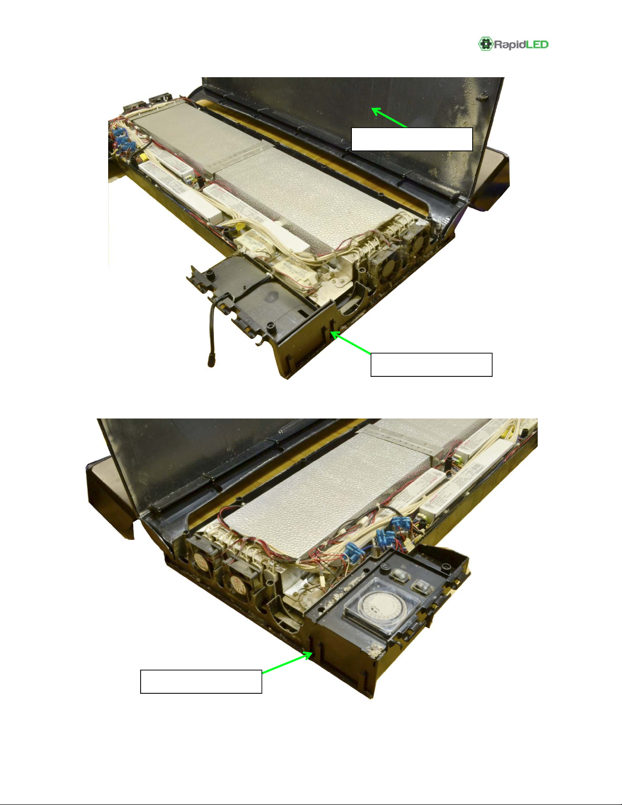
Anyandallpowerwiresmustbeunpluggedanddisconnectedbeforebeginning.Firstwewill
separatethetwohalvesofthehoodandthenremovethelargeballastsandT5bulbsockets.
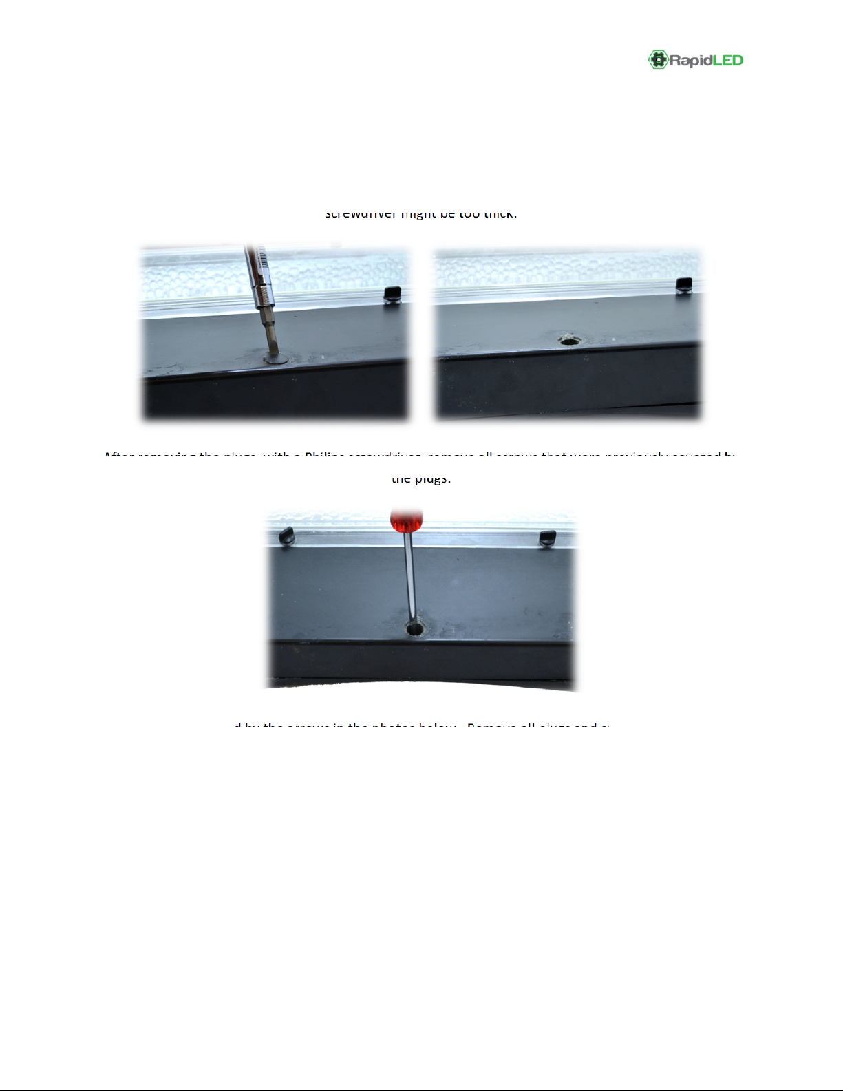
RemoveClearT5SplashGuard
First,removetheclearplasticlightcover.InstructionsforthisshouldbeinyourRSMmanual,butyou
likelywon’tneedyourmanual.Unscrewtheclearplasticcoverretainingscrewsandthenrotatethe
coveruntilitslidesoutofitsretainingclips.RemovetheT5bulbs.