RapidReel Triton GH168-WG Quick start guide

Assembly Instructions
4-Wheel Wagon Reel
Model GH168-WG
Professional Garden Hose Reels

Page 2
10 Year Warranty
Coverage
Rapid-Reel®and Reel Quick, Inc. (collectively here after referred to as the "warrantor"),
guarantees this hose reel, components and parts, unless otherwise specified, to be free
from defect, malfunction or failure in material, or workmanship, under normal use and
service, for a period of 10 years (240 months). Warranty period starts from original
invoice date.
Hose
Hose supplied by warrantor carries a warranty of sixty (60) days from original invoice date
of purchase. Hose is selected from reliable commercial sources and is recommended for
application on the basis of data supplied by the manufacturer.
Exemptions
Warranty does not cover leaking due to damage caused by the use of acid, harsh
chemicals or mineral deposits. Warranty does not apply when products are used in excess
of their rated capacities and design functions or under abnormal conditions. The effects of
corrosion, and normal wear and tear are specifically excluded from this warranty. This
warranty does not cover damage which occurs in shipment or failures which are caused
by products not supplied by the warrantor or failures which result from accidents,
mishandling, faulty installation, freezing, misuse or misapplication, abuse or neglect.
Warranty is void if the product or any part thereof has been tampered with, altered or
repaired by anyone other than warrantor or damage that is attributable to acts of God.
The warrantor covers the replacement or credit of defective parts only and does not allow
for field labor charges for removal, installation, analysis or travel expenses. In no event
shall the warrantor or its suppliers be liable for any damages, whatsoever, arising out of
the use of or inability to use this product. (Some states do not allow the exclusion of
limitation of incidental or consequential damages, so the above limitation or exclusion
may not apply to you). The warrantor and its suppliers disclaim all other expressed or
implied warranties. Some states do not allow limitations on how long an implied warranty
lasts, so the above limitation may not apply to you. This warranty gives you specific legal
rights, and you may also have other rights which vary from state to state.
THANK YOU for
your purchase.
WARRANTY
REGISTRATION
Please take a few
moments to secure your
10 year warranty by registering online.
www.rapidreel.com/pr.aspx
Questions? Problems? Missing Parts?
1-866-523-2363
(toll free) MON- FRI, 8AM to 5PM (CST)
E-mail: [email protected]
MON- FRI, 8AM to 5PM (CST)
Online: www.rapidreel.com
24/7/365
DO NOT contact or return
this item to the retailer.
Seek factory assistance using the
information below.
Contents Version 0207
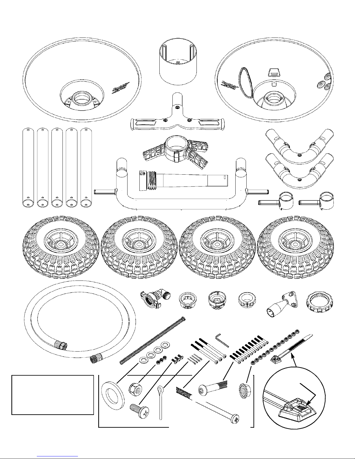
0.4501.026
0.4501.025
0.4301.130
0.2005.018
0.4202.037
0.4202.036
0.5001.166
0.5001.165
0.4102.014
0.4209.019
0.4101.056
0.4102.017
0.4209.018
0.4202.032
0.4501.030
0.5001.215
0.4501.032
0.5001.216
0.4501.034
0.4101.066
0.4202.051
0.4103.015
0.4104.002
0.4202.040
0.4501.041
0.4101.065
0.4501.042
0.4501.043
Back Flange
Front Flange
Inlet Hose
Swivel
Back Bushing
Front Bushing
Adjustable Brake
Crank Handle
Nylon Insert Nut
Kink-Free Spring
5/8” Phillips Screw
1/4” Serrated Nut
Hex Key
Hose Strap
Frame Tube
T-Handle
Frame Wye
Elbow Assembly
Tire Spindle
1-3/4” Tube Screw
Tire
Tire Washer
Cotter Pin
Axle Lock Nut
WG Axle
4-3/4” Drum Screw
Drum Spacer
WG Front Bumper
1
1
1
1
1
1
1
1
3
1
3
13
1
1
5
1
1
2
2
10
4
4
4
1
1
3
1
1
A
B
C
D
E
F
G
H
I
J
K
L
M
N
O
P
Q
R
S
T
U
V
W
X
Y
Z
AA
BB
Ref. Part # Qty. Description

U
AB
AA
R
P
BB Y
C
OQ
GHX
J
F
E
D
Page 3
Reel Specifications
5/8” Capacity ............225 feet
3/4” Capacity ............175 feet
Max. Temperature ....140° F
Max. Pressure ..........100 PSI
Patent Pending Release
Button
S
VKWZ
TL
I
MN
Reel capacities may vary depending
on hose brand and style.

Page 4
Reel & Frame Assembly
12
3
Click
Click
Actual size of
# 3 screwdriver.
3x
Press back bushing
(E) into back flange
(A). Press firmly
until all tabs “click”
into place.
Press front bushing (F) into
front flange (B). Press firmly
until all tabs “click” into place.
F
A
EA
B
Using a #3 Phillips screwdriver, connect the two
flanges and the drum spacer (AA) together using
three serrated nuts (L) and three 4-3/4” screws (Z).
Tighten firmly.
Z
AA
3x
L

56
8
7
Page 5
2x 2x
2x
2x 2x
3x
4
3x
3x
Actual size of
# 3 screwdriver.
IH
K
Q
OTL
R
TL
Using a #3 Phillips
screwdriver, attach the
handle (H) using three
nylon insert nuts (I) and
three 5/8” screws (K).
Tighten firmly
as the nylon
insert nuts will
require extra force.
Slide three frame
tubes (O) onto the
frame wye (Q).
Secure the frame
tubes to the frame
wye using three
1-3/4” screws (T)
and three serrated
nuts (L). For now,
hand tighten only.
Secure the elbows
to the frame tubes
using two 1-3/4”
screws (T) and two
serrated nuts (L).
For now, hand
tighten only.
Slide the two elbow
assemblies (R) into
the frame tubes.

11
12
Page 6
2x
2x
2x
2x
9
2x
10
2x
13
Slide the two
tire spindles (S)
onto the elbow
assemblies.
S
Be sure to take
note of proper
positioning of
spindle notches.
Slide two frame tubes (O)
onto the elbow and into the
tire spindles and align holes.
O
Attach the elbow, spindle and tube together using serrated nuts (L) and
1-3/4” screws (T) For now, hand tighten only.
T
L
NOTE: These two
serrated nuts (L)
must be placed into
the spindle notches
hex side first.
Slide the
front bumper
(BB) into the
frame tubes.
Secure the bumper to frame
tubes using two 1-3/4” screws
(T) and two serrated nut (L).
For now, hand tighten only.
BB
L
T

15 16
10x
17 18
Page 7
14
4x
P
Slide the T-handle (P)
into the frame tube.
T
M
Using the hex key (M),
firmly tighten all ten
tube screws.
Secure the T-handle to
the frame tube using a
1-3/4” screw (T) and a
serrated nut (L).
L
NOTE: Be sure
to align the stub
on the axle with
the notch in the
frame wye.
X
Y
Slide the four tires (U)
onto the tire axles.
U
Attach the axle (Y) to the
frame wye using the axle lock
nut (X). Hand tighten FIRMLY.

21 22
Page 8
19 20
4x 4x
V
W
G
Firmly push the
adjustable brake
(G) onto the axle.
Make sure it is
fully seated into
the front bushing.
Push firmly
DO NOT tighten the
brake at this time!
Slide flange assembly
onto the reel axle.
Place the four tire
washers (V) onto
the tire axles.
Insert the four cotter pins (W) through the
holes in the tire axles. Then spread the pins.

25 26
Page 9
2423
27
C
D
Lock the swivel onto the reel by aligning
it’s tabs with the slots in the axle and
then firmly press the tabs into the slots.
Swivel Removal Procedure
NOT the next step.
For reference purposes only.
Simply place the screwdriver
into the opening next to the tab
and rotate 90° either direction.
Attach swivel (D)
to inlet hose.
Hand tighten.
No sealant required.
Firmly push
the swivel
onto the axle.
If you need to remove the
swivel once the tabs are
engaged, you will need to
use a standard screwdriver.
Feed the male end
of the inlet hose (C),
through the axle.
Set wagon
reel upright.

29b 29c
Page 10
29 29a
28
32 in.
82 cm
HOSE
ATTACHMENT
Push
Push
Pull
Feed hose strap (N),
with smooth side
up, through square
hole in flange.
Align the 32” mark
with the square
hole in flange.
N
Measure 32 inches from the
female end of your garden
hose. Then lay the hose
across the top of the reel to
the right, not the left.
Left
Right
32” mark
Tighten hose
strap firmly.

33
Page 11
3231
30
Click
Click
Click
Reel in hose.
Clicking sound during
rewind is normal.
Feed female end of garden
hose through flange opening.
Attach garden hose
to brass swivel.
Hand tighten.
J
Insert kink-free spring
(J) into garden hose.
NOTE:
The Kink-Free Spring (J) is designed to prevent a hose
kink during STEP 32. Rapid Reel currently supplies this
one spring size which will fit into most 5/8" garden
hoses. However, it may not fit into certain brands, such
as Craftsman®hoses. Use of the spring is not required
and TRITON reels are designed to operate properly
without it. If the spring does not fit into your garden
hose, simply use care during STEP 32 to avoid a hose
kink. If you are going to purchase a new garden hose for
the reel, we recommend that you take the spring with
you while shopping to ensure it will slide into the hose.

Brake Adjustment
Page 12
2007© Eley Corporation
P.O. Box 22640
Lincoln, NE 68542
Patent Pending
Congratulations! Assembly and installation
are complete. Enjoy your hose reel.
1/4 turn
M
Test brake
tension, (or drag),
by pulling out a
few feet of hose.
If the brake effectively
slows the reel, and
prevents self-unwinding,
then no further adjustment
is needed.
If the brake DOES NOT
slow the reel, and self-
unwinding occurs, then
some brake adjustment
is needed.
Tighten the brake 1/4
turn using hex key (M).
DO NOT OVER-TIGHTEN!
Table of contents
Popular Lawn And Garden Equipment manuals by other brands

Grange
Grange ELITE GRANVILLE ARCH Assembly instructions

Jata hogar
Jata hogar mosquitoTRAP MATL9120 Instructions of use

Toro
Toro Groundsmaster 360 installation instructions

barebones
barebones raised grow bed user guide

Grange
Grange ELITE BOW TOP ARCH Assembly instructions

ENCLO
ENCLO Liberty Lattice ZP19054 Assembly instructions